Sharp R-239 Service Manual
Hide thumbs
Also See for R-239:
- Operation manual with cookbook (48 pages) ,
- Operation manual with cookbook (164 pages) ,
- Operation manual with cookbook (48 pages)
Table of Contents
Advertisement
Quick Links
CHAPTER 1. BEFORE SERVICING
CHAPTER 2. WARNING TO SERVICE PERSONNEL
CHAPTER 3. PRODUCT SPECIFICATIONS
CHAPTER 4. APPEARANCE VIEW
CHAPTER 5. OPERATION SEQUENCE
CHAPTER 6. FUNCTION OF IMPORTANT COMPO-
NENTS
CHAPTER 7. TROUBLESHOOTING GUIDE
CHAPTER 8. TEST PROCEDURES
SHARP CORPORATION
SERVICE MANUAL
MODELS
In interests of user-safety the oven should be restored to its
original condition and only parts identical to those specified
should be used.
CONTENTS
CHAPTER 9. TOUCH CONTROL PANEL ASSEMBLY
CHAPTER 10. PRECAUTIONS FOR USING LEAD-
FREE SOLDER
CHAPTER 11. COMPONENT REPLACEMENT AND
ADJUSTMENT PROCEDURE
CHAPTER 12. MICROWAVE MEASUREMENT
CHAPTER 13. TEST DATA AT A GLANCE
CHAPTER 14. CIRCUIT DIAGRAMS
Parts Guide
No. S5506R239PHWS
MICROWAVE OVEN
R-239(IN)
R-239(W)
This document has been published to be used
for after sales service only.
The contents are subject to change without notice.
R239(W)
Advertisement
Table of Contents

Related Manuals for Sharp R-239


Summary of Contents for Sharp R-239
- Page 1 R239(W) SERVICE MANUAL No. S5506R239PHWS MICROWAVE OVEN R-239(IN) MODELS R-239(W) In interests of user-safety the oven should be restored to its original condition and only parts identical to those specified should be used. CONTENTS CHAPTER 1. BEFORE SERVICING CHAPTER 9. TOUCH CONTROL PANEL ASSEMBLY CHAPTER 2.
-
Page 2: Table Of Contents
CONTENTS CHAPTER 1. BEFORE SERVICING [12] Procedure L: SWITCH UNIT TEST .... 8-4 GENERAL IMPORTANT INFORMATION ..1-1 [13] Procedure M: RELAY RY1, RY2) TEST..8-5 WARNING ..........1-1 [14] Procedure N: PROCEDURES TO BE TAK- EN WHEN THE FOIL PATTERN ON THE CAUTION MICROWAVE RADIATION ..1-2 PRINTED WIRING BOARD (PWB) IS CHAPTER 2. -
Page 3: Chapter 1. Before Servicing
[1] GENERAL IMPORTANT INFORMATION This Manual has been prepared to provide Sharp Corp. Service engineers with Operation and Service Information. It is recommended that service engineers carefully study the entire text of this manual, so they will be qualified to render satisfactory customer ser- vice. -
Page 4: Caution Microwave Radiation
R239(W) [3] CAUTION MICROWAVE RADIATION Personnel should not be exposed to the microwave energy which may radiate from the magnetron or other microwave generating devices if it is improperly used or connected. All input and output microwave connections, waveguides, flanges and gaskets must be secured. -
Page 5: Chapter 2. Warning To Service Personnel
Indien het water nog steeds schroevedraaier kortsluit tegen het chassis. koud is, herhaalt u de allereerste drie stappen en controleer Sharp beveelt ten sterkste aan dat, voor zover mogelijk, nogmaals de aansluitingen naar de geteste onderdelen. defecten worden opgespoord wanneer de stekker uit het Wanneer alle reparaties zijn uitgevoerd en de oven weer in stopcontact is gehaald. - Page 6 R239(W) 2 – 2...
- Page 7 R239(W) 2 – 3...
-
Page 8: Chapter 3. Product Specifications
R239(W) CHAPTER 3. R239(W) PRODUCT SPECIFICATIONS Service Manual DESCRIPTION 230 Volts Power Requirements 50 Hertz Single phase, 3 wire earthed Power Consumption 1.25 kW 800 watts nominal of RF microwave energy (IEC60705 Test Procedure) Power Output Operating frequency 2450 MHz Width 460 mm Case Dimensions Height 275 mm including foot... -
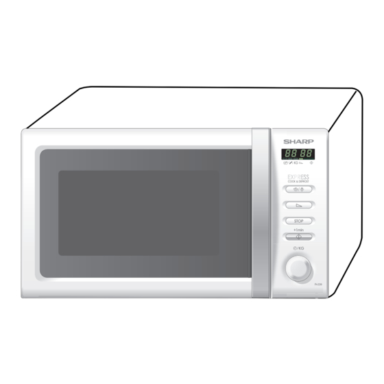
Page 9: Chapter 4. Appearance View
R239(W) CHAPTER 4. R239(W) APPEARANCE VIEW Service Manual [1] OVEN 1. Ventilation openings 2. Oven lamp 3. Door hinges 4. Door safety latches 5. See through door 6. Door seals sealing surfaces 7. Coupling 8. Control panel 9. Waveguide cover 10. -
Page 10: Chapter 5. Operation Sequence Off Condition
R239(W) CHAPTER 5. R239(W) OPERATION SEQUENCE Service Manual [1] OFF CONDITION 6. MONITOR SWITCH CIRCUIT The monitor switch SW2 is mechanically controlled by oven door, Closing the door activates all door interlock switches (1st. latch switch, and monitors the operation of the 1st. latch switch SW1, the relay 2nd. -
Page 11: Chapter 6. Function Of Important Compo
R239(W) CHAPTER 6. R239(W) FUNCTION OF IMPORTANT COMPONENTS Service Manual [1] DOOR OPEN MECHANISM [6] TEMPERATURE FUSE (TF) 150C (OVEN) The door is opened by pulling the door, refer to the Figure D-1. The temperature fuse TF located on the top of the oven cavity is designed to prevent damage to the oven if the foods in the oven catch fire due to over heating produced by improper setting of cook time or Latch Heads... -
Page 12: Chapter 7. Troubleshooting Guide Foreword
R239(W) CHAPTER 7. R239(W) TROUBLESHOOTING GUIDE Service Manual [1] FOREWORD When troubleshooting the microwave oven, it is helpful to follow the IMPORTANT: Sequence of Operation in performing the checks. Many of the possible If the oven becomes inoperative because of a blown fuse F1 T6.3A in causes of trouble will require that a specific test be performed. -
Page 13: Chapter 8. Test Procedures
R239(W) CHAPTER 8. R239(W) TEST PROCEDURES Service Manual [1] Procedure A : MAGNETRON (MG) TEST NEVER TOUCH ANY PART IN THE CIRCUIT WITH YOUR HAND OR AN INSULATED TOOL WHILE THE OVEN IS IN OPERATION. CARRY OUT 3D CHECKS. Isolate the magnetron from the high voltage circuit by removing all leads connected to the filament terminal. To test for an open circuit filament use an ohmmeter to make a continuity test between the magnetron filament terminals, the meter should show a reading of less than 1 ohm. -
Page 14: Procedure B: High Voltage Transformer (T) Test
R239(W) 1000g 1000g 1000g T1 C Heat up for 55 sec. T2 C [2] Procedure B: HIGH VOLTAGE TRANSFORMER (T) TEST WARNING: High voltages and large currents are present at the secondary winding and filament winding of the power transformer. It is very dangerous to work near this part when the oven is on. -
Page 15: Procedure E: Switch (Sw, Sw2, Sw3) Test
R239(W) [5] Procedure E: SWITCH (SW, SW2, SW3) TEST CARRY OUT 3D CHECKS. Isolate the switch to be tested and using an ohmmeter check between the terminals as described in the following table. Table: Terminal Connection of Switch Plunger Operation COM to NO COM to NC COM;... -
Page 16: Procedure J: High Voltage Fuse (F2) Test
R239(W) [10] Procedure J: HIGH VOLTAGE FUSE (F2) TEST CARRY OUT 3D CHECKS. If the high voltage fuse F2 is blown, there could be a short in the high voltage rectifier or the magnetron MG. Check them and replace the defective parts and the high voltage fuse F2. CARRY OUT 4R CHECKS. -
Page 17: Procedure M: Relay Ry1, Ry2) Test
R239(W) [13] Procedure M: RELAY (RY1, RY2) TEST CARRY OUT 3D CHECKS. Remove the outer case and check voltage between the normal open terminal of the relay RY1 and the normal open terminal of the relay RY2 on the control unit with an A.C. voltmeter. The meter should indicate 230 volts, if not check oven circuit. RY1 and RY2 Relay Test These relays are operated by D.C. -
Page 18: Chapter 9. Touch Control Panel Assem
R239(W) CHAPTER 9. R239(W) TOUCH CONTROL PANEL ASSEMBLY Service Manual [1] OUTLINE OF TOUCH CONTROL PANEL This circuit consists of 4-digits, 12-segments and 3-common elec- trodes using a Liquid Crystal Display. The touch control section consists of the following units as shown in 3) Power Source Circuit the touch control panel circuit. - Page 19 R239(W) Pin No. Signal Description COM3 OUT Terminal not used. Segment data signal. Connected to LCD.The relation between signals are as follows: LSI signal (Pin No.) LCD (segment) LSI signal (Pin No.) LCD (segment) SEG 0 (26) ----------------- S 1 SEG 6 (32) ----------------- S 7 26-37 SEG0-SEG11...
-
Page 20: Servicing For Touch Control Panel
R239(W) [3] SERVICING FOR TOUCH CONTROL PANEL 1. Precautions for Handling Electronic Components b) On some models, the power supply cord between the touch control panel and the oven proper is so long enough that This unit uses CMOS LSI in the integral part of the circuits. When han- they may be separated from each other. -
Page 21: Chapter 10. Precautions For Using Lead- Free Solder
R239(W) CHAPTER 10. R239(W) PRECAUTIONS FOR USING LEAD-FREE SOLDER Service Manual 1. Employing lead-free solder The “Main PWB” of this model employs lead-free solder. This is indicated by the “LF” symbol printed on the PWB and in the service manual. The suffix letter indicates the alloy type of the solder. -
Page 22: Chapter 11. Component Replacement And Adjustment Procedure Before Operating
4) If the outer case (cabinet) is not fitted. 4) The door is bent or warped. WARNING FOR WIRING To prevent an electric shock, take the following manners. 3) Sharp edge: 1. Before wiring, Bottom plate, Oven cavity, Waveguide flange and other metallic plate. -
Page 23: Capacitor Removal
8. Now, the turntable motor is free. 4. Where the corners have been snipped off bend corner areas flat. No sharp edges must be evident after removal of the turntable motor cover. 11 – 2... -
Page 24: Cooling Fan Motor Removal
R239(W) 2. REINSTALL TTM packing 1. Re-install the TTM packing to the turntable motor. 2. Re-install the turntable motor with the TTM packing with the single (1) screw to the oven cavity bottom plate. 3. Re-connect the wire leads to the turntable motor. Turntable motor 4. -
Page 25: Control Panel Assembly Removal
R239(W) Power Supply Oven Cavity P ower S upply Cord Back Plate Screw C ord Moulding C ord S topper Brown Wire Green/Yellow Oven C avity Wire B ack P late Blue Wire S quare Hole Noise Filter Figure C-3(a) Power Supply Cord Replacement Figure C-3(a) Figure C-3(b) Power Supply Cord Replacement [10] CONTROL PANEL ASSEMBLY REMOVAL 1. -
Page 26: Door Replacement
R239(W) [13] DOOR REPLACEMENT 1. REMOVAL 7. Re-install choke cover to door panel by pushing. NOTE: After any service to the door; 1. Disconnect the power supply cord. 1) Make sure that 1st. latch switch, 2nd. interlock relay control 2. Open the door slightly. switch and monitor switch are operating properly. -
Page 27: Chapter 12. Microwave Measurement
R239(W) CHAPTER 12. R239(W) MICROWAVE MEASUREMENT Service Manual After adjustment of door latch switches, monitor switch and door are completed individually or collectively, the following leakage test must be per- formed with a survey instrument and it must be confirmed that the result meets the requirements of the performance standard for microwave oven. REQUIREMENT The safety switch must prevent microwave radiation emission in excess of 5mW/cm at any point 5cm or more from external surface of the oven. -
Page 28: Chapter 13. Test Data At A Glance
R239(W) CHAPTER 13. R239(W) TEST DATA AT A GLANCE Service Manual PARTS SYMBOL VALUE / DATA Fuse T6.3A 250V High voltage fuse 0.6A 5kV Temperature fuse 150°C Oven lamp 240V 25W High voltage capacitor 0.91μF AC 2100V Filament < 1Ω / Filament - chassis ∞ ohm Magnetron High voltage transformer Filament winding <... -
Page 29: Chapter 14. Circuit Diagrams Oven Schematic
R239(W) CHAPTER 14. R239(W) CIRCUIT DIAGRAMS Service Manual [1] Oven Schematic SCHEMATIC NOTE: CONDITION OF OVEN 1. DOOR CLOSED. NOTE: " " indicates components with potentials above 250V NOISE FILTER TF: TEMP. FUSE N.O. COM. 2ND. INTERLOCK RELAY (RY-2) (RY-1) N.O. -
Page 30: Pictorial Diagram (Figure S-1)
R239(W) [2] Pictorial Diagram (Figure S-1) Figure S-1. Pictorial Diagram 14 – 2... -
Page 31: Control Unit Circuit (Figure S-2)
R239(W) [3] Control Unit Circuit (Figure S-2) Figure S-2. Control Unit Circuit 14 – 3... -
Page 32: Printed Wiring Board
R239(W) [4] Printed Wiring Board CN-G IC SIDE JUMP1 (JUMP A) JUMP4 D1 D3 VRS1 SW100 Figure S-3. Printed Wiring Board of Power Unit Figure S-4. Printed Wiring Board of Switchr Unit 14 – 4... - Page 33 [1] OVEN PARTS PANEL PARTS [2] DOOR AND CONTROL INDEX TOP PAD ASSEMBLY FPADBA598WRKZ POLYETHYLENG BAG SSAKHA014WRE0 DOOR PROTECTION SHEET CABINET COVER for R-239(W) SPADPA580WRE0 SPADFA449WRE0 6-4 INSTRUCTION BOOK MICROWAVE OVEN AC CORD PAD 6-1 TURNTABLE TRAY SPADBA371WRE0 BOTTOM PAD ASSEMBLY...
- Page 34 R239(W) [1] OVEN PARTS 4-11 7-10 4-12 4-10...
- Page 35 High voltage transformer QFS-TA014WRE0 Temperature fuse 150C (Oven) RMOTDA265WRZZ Turntable motor RMOTDA173WRE0 Turntable motor (Interchangeable) RMOTDA253WRZZ Turntable motor (Interchangeable) CABINET PARTS GCABUA958WRPZ Outer case cabinet [R-239(W)] GCABUA966WRPZ Outer case cabinet [R-239(IN)] GDAI-A377WRWZ Bottom plate GLEGPA104WREZ Foot OVENPARTS PHOK-A146WRFZ Latch hook LBNDKA168WRPZ...
- Page 36 R239(W) [2] DOOR AND CONTROL PANEL PARTS 5-10 5-10...
- Page 37 MARK RANK [2] DOOR AND CONTROL PANEL PARTS DPWBFC487WRUZ Control unit DPWBFC494WRKZ Switch unit GMADIA144WRFZ Display window HPNLCB933WRRZ Control panel [R-239(W)] HPNLCB935WRRZ Control panel [R-239(IN)] JBTN-B321WRRZ Select button [R-239(W)] JBTN-B318WRRZ Select button [R-239(IN)] JKNBKA729WRFZ Timer knob [R239(W)] JKNBKA730WRTZ Timer knob [R239(IN)] XEPS730P08XS0 Screw;...
- Page 38 R239(W) INDEX PRICE PART PRICE PART PARTS CODE PARTS CODE RANK MARK RANK RANK MARK RANK [ D ] PCUSUA501WRP0 1-4-11 PDUC-A908WRWZ 1-4-4 DPWBFC487WRUZ 2-3-1 PDUC-A909WRPZ 1-4-9 DPWBFC494WRKZ 2-3-2 PGLSPA633WREZ 2-5-7 [ F ] PHOK-A146WRFZ 1-4-1 FDORFA397WRTZ 2-5-1 PPACGA176WREZ 1-4-10 FH-DZA115WRKZ 1-1-2 PSHEPA782WREZ...
- Page 40 COPYRIGHT © 2005 BY SHARP CORPORATION ALL RIGHTS RESERVED. No part of this publication may be reproduced, stor- ed in retrieval systems, or transmitted in anyform or by any means, electronic, mechanical, photocopy- © ing, recording, or other wise, without prior written...