
Related Manuals for HP Aruba 3810M Series


Summary of Contents for HP Aruba 3810M Series
- Page 1 Aruba 3810M Switches Installation and Getting Started Guide Part Number: 5998-8461a Published: June 2017 Edition: 2...
- Page 2 © Copyright 2011, 2016 Hewlett Packard Enterprise Development LP The information contained herein is subject to change without notice. The only warranties for Hewlett Packard Enterprise products and services are set forth in the express warranty statements accompanying such products and services. Nothing herein should be construed as constituting an additional warranty.
-
Page 3: Table Of Contents
Contents 1 Introducing the 3810M switches................6 Front of the Switches..........................7 Network Ports..........................9 Management Ports........................11 Console Ports...........................11 Auxiliary (Aux) Port........................11 Switch and Port LEDs on Front of the switches................11 LED Mode Select Button and Indicator LEDs................18 Reset and Clear Buttons.......................19 Flex Port Slot and Module Support....................20 Back of the Switches..........................20 Power Supplies..........................21 Power Connector...........................21... - Page 4 Chain Topologies...........................48 Ring Topologies..........................50 Mesh Topologies..........................51 Sample Network Topologies.......................53 3 Getting Started With Switch Configuration............58 Recommended Minimal Configuration....................58 Minimal Configuration Through the Console Port Connection............58 Where to Go From Here: Networked Connections................60 Using the IP Address for Remote Switch Management..............61 Starting a Telnet Session.......................61 Starting a Web Browser Session....................61 4 Replacing Components..................63...
- Page 5 Pin Assignments........................91 Crossover Twisted-Pair Cable for 10 Mbps or 100 Mbps Network Connection......91 Cable Diagram.........................91 Pin Assignments........................92 Straight-Through Twisted-Pair Cable for 1000 Mbps Network Connections.........92 Cable Diagram.........................92 Pin Assignments........................93 8 Support and other resources................94 Accessing Hewlett Packard Enterprise Support.................94 Before Calling Support........................95 Accessing updates..........................95 Websites.............................95 Customer self repair...........................96...
-
Page 6: Introducing The 3810M Switches
1 Introducing the 3810M switches The Aruba 3810M are multiport switches that can be used to build high-performance switched networks. These switches are store-and-forward devices offering low latency for high-speed networking. The 3810M switches also support a field-replaceable Redundant Power Supply and fan tray, Power over Ethernet (PoE/PoE+) technologies, full network management capabilities and a flexible uplink port slot. -
Page 7: Front Of The Switches
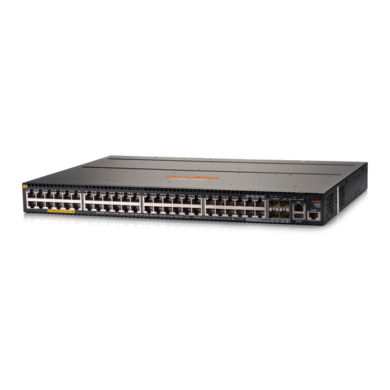
Front of the Switches Figure 1 Front of all the 3810M Switches Table 1 Front of all the 3810M Switches Label and Description Label Description Aruba 3810M 24G 1-slot Switch (JL071A) Aruba 3810M 48G 1-slot Switch (JL072A) Aruba 3810M 24G PoE+ 1-slot Switch (JL073A) Aruba 3810M 48G PoE+ 1-slot Switch (JL074A) Aruba 3810M 16SFP+ 2-slot Switch (JL075A) Aruba 3810M 40G 8 HPE Smart Rate PoE+ 1-slot Switch (JL076A) - Page 8 Figure 2 Front of 3810M Flex Port Modules Table 2 3810M Flex Port Modules Label and Description Label Description Aruba 3810M 1QSFP+ 40GbE Module (JL078A) Aruba 3810M 2QSFP+ 40GbE Module (JL079A) Aruba 3810M 4SFP+ Module (JL083A) Port LEDs Flex Port Module Status LED Introducing the 3810M switches...
-
Page 9: Network Ports
Figure 3 Example of 3810M Switches Table 3 3810M Switches Labels and Description Label Description Switch Port LEDs LED Mode button Speed, PoE*, Usr LEDs 4, 5 Reset, Clear buttons Back Module Status LED Aux port status LED USB/Auxiliary Port RJ Serial Console Micro USB Console Global Status, Unit Identification LEDs... - Page 10 Table 4 Network Ports (continued) 10/100/1000 10/100/1000 Product non-PoE PoE/PoE+ SFP+ Ports Model name SmartRate number RJ-45 ports RJ-45 ports Aruba 3810M 40G 8 JL076A HPE Smart Rate PoE+ 1-slot Switch Aruba 3810M 1QSFP+ JL078A 40GbE module Aruba 3810M 2QSFP+ JL079A 40GbE module Aruba 3810M 4SFP+...
-
Page 11: Management Ports
Table 5 Optional Network Connectivity, Speeds and Technologies (continued) Fiber (single 10-Gig ER mode) 40-Gig Direct Copper Not Applicable Attach 1/3/5 m (twinaxial) Fiber 40-Gig SR4 (multimode) 40 Gbps Fiber 40-Gig ESR4 (multimode) Fiber (single 40-Gig LR4 mode) Smart Rate Copper 1/2.5/5/10 Smart Rate... - Page 12 Figure 4 Switch and Port LEDs for JL071A, JL072A, JL073A*, JL074A*, and JL076A* Table 6 Switch and Port LEDs Label and Description for JL071A, JL072A, JL073A*, JL074A*, and JL076A* Label Description Switch Port LEDs LED Mode button Speed LED PoE LED* Usr LED Reset button Clear button...
- Page 13 Table 7 Switch and Port LEDs Label and Description for JL075A Label Description Switch Port LEDs LED Mode button Speed LED Usr LED Reset button Clear button Back Module status LED Aux Port status LED Unit Identification LED Global status LED Table 8 Front of Switch Status and Mode LED Behavior Switch LEDs...
- Page 14 Table 8 Front of Switch Status and Mode LED Behavior (continued) Switch LEDs Function State Meaning stacking module) has failed self test or is experiencing a fault condition. Flashes simultaneously with the Global Status LED flashing orange. Aux Port Activity Indicates data transfer on Solid Green USB installed and successfully...
- Page 15 Table 8 Front of Switch Status and Mode LED Behavior (continued) Switch LEDs Function State Meaning the error. The rest of the Port LEDs will display normal PoE status. PoE mode is not selected. User Mode Selected When stacking is enabled, On Green User Mode is selected.
- Page 16 Table 9 Port LEDs and Mode Behavior (continued) Switch LEDs Function State/Mode Meaning Slow Flash Orange* The corresponding port has failed its self-test. Flashes simultaneously with the Global Status LED flashing orange. The Port is disabled, not connected, or not receiving link.
- Page 17 Table 9 Port LEDs and Mode Behavior (continued) Switch LEDs Function State/Mode Meaning Slow Flash Orange* Stack Member is in a known fault condition (i.e. Fan fault, PSU fault, etc.). The Global Status LED on all stack members will also Slow Flash Orange.
-
Page 18: Led Mode Select Button And Indicator Leds
Example 1 Example of USER mode behavior Assume you have a 4-member stack, in a ring topology, with member numbers 1, 2, 3 and 5. Member 1 is the commander and member 3 is rebooting. In USER mode, the members will show the following on their port LEDs: Port 1 LED Port 2 LED... -
Page 19: Reset And Clear Buttons
Stacking Notes: For 3810M switches that are in a stack, the Mode select button on every switch in the stack controls the LED mode for all the switches in the stack. Using the Mode select button on one switch in the stack changes the LED mode for the entire stack. If there is a combination of PoE/PoE+ switches and non-PoE switches in the stack, when any of the Mode select buttons is pressed to put the stack into PoE mode, the non-PoE switches indicate no PoE support by not illuminating any of the Mode indicator LEDs or any... -
Page 20: Flex Port Slot And Module Support
To accomplish this: Do this: This will happen: Restore the factory default 1. Press Clear and Reset The switch removes all configuration configuration simultaneously. changes, restores the factory default configuration, and runs self test. 2. While continuing to press Clear, release Reset. -
Page 21: Power Supplies
Figure 6 Back of the 3810M Switches Table 11 Back of the 3810M Switches Label and Description Label Description Fan Status LED Stacking Module Slot Management/OOBM port AC Power connector/Power Supply slot 1 Redundant Power Supply slot 2 Power Supplies There are three power supplies that can be installed into the 3810M switches: Aruba X371 12VDC 250W 100-240VAC Power Supply (JL085A)—A 250 watt power supply for the non-PoE switches. -
Page 22: Fan Tray Assembly
Fan Tray Assembly The 3810M switches have a field-replaceable fan tray. If necessary, the fan tray can be replaced while the switch is operating. For more information, see Replacing the Fan Tray. Out-of-Band Management (OOBM) Port This RJ-45 port is used to connect a dedicated management network to the switch. LEDs on the Back of the Switches This section describes the LEDs on the back of the switch. -
Page 23: 3810M Stacking Module
Table 13 LEDs on the Back of the Switch (continued) Switch LEDs Function State Meaning This LED is a copy of the minutes (1-1440). The UID LED on the front of the default is 30 minutes. chassis. The LED turns off after the timeout period has expired. -
Page 24: Stacking Module Leds
Figure 8 Front of 3810M 4-Port Stacking Module Table 14 Front of 3810M 4-Port Stacking Module Label and Description Label Description Stacking Module Status LED Extractor Handles Link LEDs Stacking Connectors Retaining Screw The 3810M 4-Port Stacking Module JL084A has the following features: Four stacking connectors for connecting the 3810M switch to other 3810Ms in a stacked topology (chain, ring, or mesh). -
Page 25: Switch Features
Table 15 Stacking Module LEDs (continued) Name Function Mode Description should be synchronized with the switch Global Status LED. The Global Status and Back LED should also be flashing. Fast Flash Orange Stacking module or one or more of its ports is experiencing an alert condition. - Page 26 to 30W per port to power IP phones, wireless access points, indoor web cameras, and more. For more information, see the HPE Power over Ethernet (PoE/PoE+) Planning and Implementation Guide, available from http://www.hpe.com/networking/support. The switches support 802.3af and 802.3at standard devices and some pre-standard PoE devices.
- Page 27 An auxiliary port (USB Type A connector) for processing a USB command file and updating switch software. Low power operation: ◦ Ports on a switch or stack member may be set to operate at reduced power. ◦ Port status LEDs may be turned off. ◦...
-
Page 28: Installing The Switch
2 Installing the Switch This chapter shows how to install the switch. The 3810M switches come with an accessory kit that includes the brackets for mounting the switch in a standard 19-inch telco rack, in an equipment cabinet, and with rubber feet that can be attached so the switch can be securely located on a horizontal surface. -
Page 29: Installation Procedures
Power cord, one of the following: Aruba 3810M PoE+ Switches North America 8121-0973 Australia 8121-0857 North America high line 8121-0941 Brazil 8121-1265 South Africa/India 8121-1483 Europe/South Korea 8120-5336 Israel 8121-1009 China 8121-1034 United Kingdom/Hong 8120-5334 Argentina 8121-1481 Kong/Singapore/Malaysia Switzerland 8120-5339 Chile 8120-8389 Danish... - Page 30 Verify the switch passes self test ( “ 2. Verify the Switch Boots Correctly” (page 32) Plug the switch into a power source and observe that the LEDs on the switch’s front panel indicate correct switch operation. When self test is complete, unplug the switch. (Optional) Install the stacking module ( 3.
-
Page 31: Installation Precautions
Installation Precautions: Follow these precautions when installing the 3810M switches. WARNING! The rack or cabinet should be adequately secured to prevent it from becoming unstable and/or falling over. Devices installed in a rack or cabinet should be mounted as low as possible, with the heaviest devices at the bottom and progressively lighter devices installed above. -
Page 32: Verify The Switch Boots Correctly
Figure 9 Air flow direction of the 3810M switches 2. Verify the Switch Boots Correctly NOTE: For steps 2 and 3, if an 3810M switch is powered on for the first time without a stacking module installed, stacking will be disabled and that will be saved in the switch's running configuration. - Page 33 Connect the power cord supplied with the switch to the power connector on the back of the switch, and then into a properly grounded electrical outlet. Figure 10 Connecting the Power cord NOTE: The 3810M switches do not have a power switch. They are powered on when the power cord is connected to the switch and to a power source.
-
Page 34: Led Behavior
Table 16 Example of an 3810M-48-port PoE+ switch Label and Description Label Description Switch Port LEDs Mode LEDs Back LED Global Status and UID LEDs When the switch is powered on, it performs its diagnostic self test and initialization. This boot process, depending on switch model and configuration, takes approximately 1-2 minutes to complete. -
Page 35: Verifying The Module Is Installed Correctly
Tighten the captive screws until they are snug – do not overtighten them. Figure 12 Installing the Module Verifying the Module is Installed Correctly Observe the Back and Global Status LEDs on front of the switch, and the Module Status LED on the module to verify module is installed properly. -
Page 36: Installing The Flex Port Module
module is installed properly and has passed the self test, as described in the “LED Behavior” table Stacking Module LED Behavior. Table 18 Stacking Module LED Behavior Display for a Properly Installed Module Global After boot-up sequencing, LEDs are on steady green. Status and Back LEDs on front of... -
Page 37: Mount The Switch
Figure 14 Install Flex Port Module 5. Mount the Switch After the switch passes self test, the switch is ready to be mounted in a stable location. The 3810M switches can be mounted in these ways: in a rack or cabinet on a horizontal surface For other mounting options contact your local Hewlett Packard Enterprise authorized network reseller or Hewlett Packard Enterprise representative. -
Page 38: Rack Mounting The 3810M Switch In A 2-Post Rack
Rack Mounting the 3810M switch in a 2-post rack Use a #1 Phillips (cross-head) screwdriver and attach the mounting brackets to the switch with the included 8-mm M4 screws. Figure 15 Attaching the mounting brackets to the switch NOTE: The mounting brackets have multiple mounting holes and can be rotated allowing for a wide variety of mounting options. -
Page 39: Rack Mounting The 3810M Switch In A 4-Post Rack
Rack Mounting the 3810M switch in a 4-post rack Using the (J9583A) X410 E-Series 1U Universal Rack Mounting Kit, use a #1 Phillips (cross-head) screwdriver and attach the slider brackets to the switch with the included 8-mm M4 screws. Figure 17 Attaching the rail kit slider brackets to the switch Install the rails in the rack. -
Page 40: Horizontal Surface Mounting
Figure 19 Installing the switch Securing the switch in rack after installation. Figure 20 Secure the switch Horizontal Surface Mounting Place the switch on a table or other horizontal surface. The switch comes with rubber feet in the accessory kit that can be used to help keep the switch from sliding on the surface. Attach the rubber feet to the four corners on the bottom of the switch within the embossed angled lines. -
Page 41: Optional) Installing The Stacking Cables
6. (Optional) Installing the Stacking Cables NOTE: Hot swapping stacking cables is supported. You can install or remove a stacking cable with the switch powered on. a. Slide in the stacking cable connector until it clicks into place. Pull on the cable connector (not the tab) to make sure that it is fully latched. -
Page 42: Removing The Transceiver
seconds, with the worst case being 5 seconds. If the transceiver is removed before the authentication completes a self test failure will be reported. WARNING! The Hewlett Packard Enterprise transceivers are Class 1 laser devices. Avoid direct eye exposure to the beam coming from the transmit port. Figure 22 Installing a transceiver Removing the transceiver: NOTE:... -
Page 43: Optional) Installing A Second Power Supply
Stacking Note: If you are stacking your 3810M switches, then the first switch you should power on is the switch that you want to be the stack Commander. The second switch that you power on should be the one that you want to be the stack Standby. For the other switches in the stack, their member ID will be determined by the order in which they are booted. -
Page 44: Optional) Connect A Management Console
10. (Optional) Connect a Management console The switch has a full-featured, easy to use console interface for performing switch management tasks including: Monitor switch and port status and observe network activity statistics. Modify the switch’s configuration to optimize switch performance, enhance network traffic control, and improve network security. -
Page 45: Console Cable Pinouts
IMPORTANT: You must use the out-of-band console connection to minimally configure the switch with an IP address and subnet mask before you can use an in-band or out-of-band networked connection to manage the switch. Continue with Minimal Configuration Through the Console Port Connection for more information. -
Page 46: Connect The Network Cables
Figure 23 RJ-45 to DB-9 pinouts Table 19 Mapping of RJ-45 to DB-9 RJ-45 (Signal reference from Chassis) DB-9 (Signal reference from PC) Reserved Reserved Reserved Reserved Reserved 11. Connect the Network Cables Connect the network cables, described under “Cabling Infrastructure” (“... -
Page 47: Using The Rj-45 Connectors
Using the RJ-45 Connectors Figure 24 Connecting an RJ-45 To connect: Push the RJ-45 plug into the RJ-45 jack until the tab on the plug clicks into place. When power is on for the switch and for the connected device, the port LED should come on half-bright to indicate link is established. -
Page 48: Chain Topologies
extended virtual switch. The stacking topologies supported depend on the number of switches being stacked. The stacking cables and connections operate independently of any layer 2 or layer 3 network protocols and features, including Spanning Tree. When multiple switches are stacked, they behave as a single, virtual switch with additional network ports being supplied by the stack members. - Page 49 Figure 25 Typical Chain Topology Cable connection examples for stacked chains are illustrated in Cable Connection Examples for Chain Topologies. Figure 26 Cable Connection Examples for Chain Topologies Stacking Information and Topologies...
-
Page 50: Ring Topologies
Table 20 Cable Connection for Chain Topologies Label and Description Label Description 2-switch chain 3-switch chain 5-switch chain Ring Topologies Up to 10 switches may also be connected in closed ring topologies. Ring topologies afford some protection from a single failure because communication between the switches continues, in a direction away from the failure. -
Page 51: Mesh Topologies
Figure 28 Cable connection examples for Ring Topologies Table 21 Cable Connection for Ring Topologies Label and Description Label Description 2-switch ring 3-switch ring 5-switch ring Mesh Topologies Two to five switches may be stacked using mesh topologies. In mesh topologies, every switch in the stack is connected to every other switch in the stack. Hence, with four stacking ports on the Stacking Module, the maximum number of switches that can be meshed together is limited to five. - Page 52 Figure 29 Meshed Topologies Table 22 Meshed Topologies Label and Description Label Description 2-switch mesh 3-switch mesh 4-switch mesh 5-switch mesh Cable connection examples for stacked redundant and meshed topologies are illustrated in Figure 30 (page 53). Installing the Switch...
-
Page 53: Sample Network Topologies
Figure 30 Cable Connection Examples for Redundant and Meshed Topologies Table 23 Cable Connection for Redundant and Meshed Topologies Label and Description Label Description 2-switch mesh 3-switch mesh 4-switch mesh 5-switch mesh Sample Network Topologies This section shows a few sample network topologies in which the switch is implemented. For more topology information, visit the product’s website at http://www.hpe.com/networking/support. - Page 54 Notice that the end node devices are connected to the switch by straight-through or crossover twisted-pair cables. Either cable type can be used because of the “IEEE Auto MDI/MDI-X” features on the switch. Figure 31 Example as a Desktop Switch Implementing PoE/PoE+ This illustration is an example of the switch being configured to supply PoE/PoE+ power to end devices such as IP telephones and wireless access points (WAPs).
- Page 55 Figure 32 Example as a Segment Switch The Switch also works well as a segment switch. That is, with its high performance, it can be used for interconnecting network segments – simply connect the network hubs that form those segments to the switch, or you can also connect other switches. In the illustration above, two “Fast”...
- Page 56 Figure 33 Example as a Segment Switch Implementing PoE/PoE+ As shown in Example as a Segment Switch Implementing PoE/PoE+, the IP telephones have been inserted in between the 3810M-PoE+ switch and the PCs, and a WAP has been connected to the 3810M-PoE+ switch. Only devices directly connected to the PoE+ switches can receive PoE/PoE+ power.
- Page 57 Figure 34 Example of connecting to a Backbone Switch For example, you can use an Aruba 5406R zl Switch to interconnect each of your smaller switched workgroups to form a larger switched network. All the devices in this network can communicate with each other.
-
Page 58: Getting Started With Switch Configuration
3 Getting Started With Switch Configuration This chapter is intended as a guide for using the console Switch Setup screen to quickly assign an IP (Internet Protocol) address and subnet mask to the switch, set a Manager password, and, optionally, configure other basic features. For more information on using the switch console and the other switch management interfaces: the web browser interface and the SNMP management tool, Aruba IMC, see the Management and Configuration Guide, which is on the Hewlett Packard Enterprise website at... - Page 59 Set up a console connection through the Console port by following the procedure described Setting Up a Console Connection. The 3810M command-line prompt should be displayed on the console screen, typically with the switch model number; for example: Aruba 3810M# At the prompt, enter the setup command to display the Switch Setup screen.
-
Page 60: Where To Go From Here: Networked Connections
Parameter Default TimeP Mode Disabled Optional; The method the switch uses to acquire the TimeP server address. IP Config DHCP/Bootp Set to Manual unless a DHCP/Bootp server is used on your network to (DHCP/Bootp) configure IP addressing. IP Address xxx.xxx.xxx.xxx Recommended;... -
Page 61: Using The Ip Address For Remote Switch Management
The following types of networked connections are supported on a 3810M Switch: Out-of-band networked connection through the dedicated Management port To use: Connect an RJ-45 network cable to the Mgmt port to manage a 3810M Switch through Telnet from a remote PC or UNIX workstation. To use this port, the switch must have an IP address. - Page 62 as the URL. No additional software installation is required to make this interface available; it is included in the switch’s onboard software. The following illustration shows a typical web browser interface screen. Figure 36 Web browser interface screen For more information on using the web browser interface, see the Management and Configuration Guide, which is on the Hewlett Packard Enterprise website at http://www.hpe.com/networking/ support.
-
Page 63: Replacing Components
4 Replacing Components This chapter shows you how to remove and install the following components: Fan tray (see Replacing the Fan Tray) Power Supply (see Replacing the Power Supply) Stacking Module (see Replacing the Stacking Module) Flex Port Module (see Replacing the Flex Port Module) CAUTION:... -
Page 64: Replacing The Power Supply
Figure 37 Fan tray retaining screw and handle Table 24 Replacing Fan Tray Label and Description Label Description Retaining Screw Handle Replacing the Power Supply If the 3810M switch is configured with redundant power supplies, the switch will not suffer any loss of traffic or performance if a power supply fails. -
Page 65: Replacing The Stacking Module
Figure 38 Replacing a failed power supply Table 25 Replacing Failed Power Supply Label and Description Label Description Handle Lock Mechanism Insert the new power supply. Slide it in all the way in until the locking mechanism locks. Replacing the Stacking Module The 3810M Stacking Module is not hot swappable. -
Page 66: Replacing The Flex Port Module
Figure 39 Replace Stacking Module. Replacing the Flex Port Module The 3810M Flex Port Module is not hot swappable. To replace a Flex Port module: Execute flexible-module <A/B> remove, or in case of stacking, stacking <member Id> flexible-module <A/B> remove. Remove the new Flex Port module from it’s packaging, being careful to not touch any of the circuitry on the board. - Page 67 Figure 40 Replace Flex Port module. Replacing the Flex Port Module...
-
Page 68: Troubleshooting
5 Troubleshooting This chapter describes how to troubleshoot your switch. This document describes troubleshooting mostly from a hardware perspective. You can perform more in-depth troubleshooting on the switch using the software tools available with the switch, including the full-featured console interface, the built-in web browser interface, and IMC, the SNMP-based network management tool. -
Page 69: Diagnosing With The Leds
Connectors” for pinouts and correct cable wiring. A category 5 or greater cable tester is a recommended tool for every 100Base-TX and 1000Base-T network installation. Check the port configuration. A port on your switch may not be operating as expected because it is administratively disabled in the configuration. - Page 70 Table 26 Switch LED Error Indicators (continued) Chassis Mode/Status Back side of chassis Global Status Port Status FP/IM Diag Back Stacking Stacking Tips Port Status Module Port Slow Slow Slow Flash Flash Flash Orange Orange Orange*** Slow Slow Solid Flash Flash Green*** Orange...
- Page 71 Problem Solution Packard Enterprise Customer Support Services” (page 79). One or more of the switch cooling fans may have Try disconnecting power from the switch and wait a few failed. moments. Then reconnect the power to the switch and check the LEDs again. If the error indication reoccurs, one or more of the fans has failed.
- Page 72 Problem Solution NOTE: If the switch port configuration is changed to one of the fixed configuration options (for example, 100 Mbps/Full Duplex), then the port operates as MDI-X only and you must use the correct type of cable for the connection.
- Page 73 Problem Solution the normal operation of protocols, such as Spanning If it does not, the problem may be with the cabling Tree, LACP, or GVRP features. between the devices, the connectors on the cable, or the configuration of the device on the remote end of the cable.
- Page 74 Table 27 Stacked Switch and Stacking Module LED Error Indicators (continued) Chassis Status Mode/Status Back side of chassis Global Status Diag Port LED Stacking Tips Back LED Stacking Port Module Slow Flash Slow Flash Solid Green Slow Flash Slow Flash Slow Flash Orange Orange...
- Page 75 Table 28 Diagnostic Tips for Stack Errors: (continued) Problem Solution NOTE: Slow green flash LED represent stacking member Fast green flash LED represent commander member ID of that chassis. Other solid green LED represent other stacking members. The Stacking Module was installed in the switch while Reset or power cycle the switch to reboot it.
-
Page 76: Proactive Networking
Table 28 Diagnostic Tips for Stack Errors: (continued) Problem Solution are disabled. As a result, all the port LEDs in other than user mode are off for those switches. You have tried to merge two stacks that have different 1. Select one of the stacks as the one to retain. Stack IDs –... -
Page 77: Hardware Diagnostic Tests
The following interfaces provide tests, indicators, and an event log that can be used to monitor the switch and its network connections and to help you take advantage of these proactive networking features: IMC - an SNMP-based network management tool that is included with your switch. A graphical web browser interface that you can use to manage your switch from a PC running a supported web browser, for example Microsoft Internet Explorer, and Netscape Communicator. -
Page 78: Testing Switch-To-Device Network Communications
Testing Switch-to-Device Network Communications You can perform the following communication tests to verify the network is operating correctly between the switch and any connected device that can respond correctly to the communication test. Link Test -- a physical layer test that sends IEEE 802.2 test packets to any device identified by its MAC address. -
Page 79: Downloading New Switch Software
To restore the factory default configuration using the console, execute the erase startup-config command from the console command prompt. For stacked switches, reset stacking configurations to factory defaults by executing the stacking factory-reset command. Downloading New Switch Software Software Updates can be downloaded to the switch through several methods. See “Support and other resources”... -
Page 80: Specifications
6 Specifications Switch Specifications Physical Product Weight Width Depth Height Aruba 3810M 24G 1-slot Switch 6.5 kg (14.28 lb (JL071A) Aruba 3810M 48G 1-slot Switch 6.7 kg (14.7 lb) (JL072A) Aruba 3810M 24G PoE+ 1-slot 6.7 kg (14.84 Switch (JL073A) 430 mm (17.0 in) 442.5 mm (17.4 in) 43 mm (1.7 in) -
Page 81: Environmental
Environmental Environmental Aruba 3810M switches Operating Temperature: 0°C to 45°C (32°F to 113°F) Relative Humidity: 15% to 95% at 40°C (104°F) noncondensing Non-Operating Temperature: -40°C to 70°C (-40°F to 158°F) Non-Operating Relative Humidity: 15% to 90% at 65°C (149°F) Maximum Operating Altitude: 3.0 km (10,000 ft) Non-Operating Altitude: 4.6 km (15,000 ft) -
Page 82: Connectivity Standards
IEC60825:2007 (Applies to products with lasers) UL60950-1, CSA 22.2 No 60950-1 UL62368-1 Ed.2 EN60850-1:2007 / IEC 60825-1: 2007 Class1 Class 1 Laser Products / Laser Klasse 1 Connectivity Standards Table 31 Technology Standards and Safety Compliance Laser safety information Compatible with these EN/IEC standard SFP ("mini-GBIC") Technology... -
Page 83: Stacking Module Specifications
Table 31 Technology Standards and Safety Compliance (continued) Laser safety information Compatible with these EN/IEC standard SFP ("mini-GBIC") Technology SFP+Lasers IEEE standards compliance Lasers 10-Gig ER IEEE 802.3ae EN/IEC 60825 Class 1 Laser 10GBASE-ER Product Laser Klasse 1 40-Gig Direct Attach (not an IEEE standard) 40-Gig SR4 IEEE 802.3ba... -
Page 84: Environmental
Environmental Flex Port Module Environmental 0°C to 45°C (32°F to 131°F) Operating Temperature: Relative Humidity: 15% to 95% at 40°C (104°F) noncondensing Non-Operating Temperature: -40°C to 70°C (-40°F to 158°F) Non-Operating Relative Humidity: 15% to 90% at 65°C (149°F) Maximum Operating Altitude: 3.0 km (10,000 ft) Non-Operating Altitude: 4.6 km (15,000 ft) -
Page 85: Cabling And Technology Information
2.5 Gbps Operation Category 5e, 100-ohm-4-pair UTP or STP cable, complying with IEEE 802.ab 1000BASE-T specifications. “Note on HP Smart Rate 2.5 Gb/s Cable Requirements” below. 5 Gbps Operation Category 5e or better, 100-ohm-4-pair UTP or STP cable. Category 6 or better is recommended. - Page 86 The patch cables are frequently overlooked when testing cable and they must also comply with the cabling standards. Note on HP Smart Rate 2.5 Gb/s Cable Requirements The 2.5 Gb/s Smart Rate operates on cable installations that are designed to support 1000BASE-T operation.
-
Page 87: Technology Distance Specifications
2,000 meters 100-BX single mode fiber 0.5 - 10,000 meters 1000-T twisted-pair copper up to 100 meters 2.5Gb/s HP twisted-pair copper up to 100 meters Smart Rate 5Gb/s HP twisted-pair copper Cat 5e - up to 100 meters... -
Page 88: Mode Conditioning Patch Cord
Table 33 Technology Distance Specifications (continued) Technology Supported cable type Multimode fibermodal bandwidth Supported distances 10-Gig SR multimode fiber 160 MHz*km 2 - 26 meters 200 MHz*km 2 - 33 meters 400 MHz*km 2 - 66 meters 500 MHz*km 2 - 82 meters 2000 MHz*km 2 - 300 meters 10-Gig LRM... -
Page 89: Installing The Patch Cord
NOTE: Most of the time, if you are using good quality graded-index multimode fiber cable that adheres to the standards listed in Cabling Specifications, there should not be a need to use mode conditioning patch cords in your network. This is especially true if the fiber runs in your network are relatively short. -
Page 90: Straight-Through Twisted-Pair Cable For 10 Mbps Or 100 Mbps Network Connections
If you happen to use a correctly wired crossover cable, though, the switch will still be able to automatically detect the MDI/MDI-X operation and link correctly to the connected device. Other Wiring Rules: All twisted-pair wires used for 10 Mbps, and 100 Mbps operation must be twisted through the entire length of the cable. -
Page 91: Pin Assignments
NOTE: Pins 1 and 2 on connector “A” must be wired as a twisted pair to pins 1 and 2 on connector “B”. Pins 3 and 6 on connector “A” must be wired as a twisted pair to pins 3 and 6 on connector “B”. Pins 4, 5, 7, and 8 are not used in this application, although they may be wired in the cable. -
Page 92: Pin Assignments
Pin Assignments Switch End (MDI-X) Hub or Switch Port, or Other MDI-X Port End Signal Pins Pins Signal receive + transmit - receive - transmit + transmit + receive - transmit - receive + Straight-Through Twisted-Pair Cable for 1000 Mbps Network Connections 1000Base-T connections require that all four pairs or wires be connected. -
Page 93: Pin Assignments
Pin Assignments For 1000Base-T operation, all four pairs of wires are used for both transmit and receive. Twisted-Pair Cable/Connector Pin-Outs... -
Page 94: Support And Other Resources
Accessing Hewlett Packard Enterprise Support For live assistance, go to the Contact Hewlett Packard Enterprise Worldwide Support website: www.hpe.com/assistance To access documentation and support services, go to the HP Support Center – Hewlett Packard Enterprise Support Center website: www.hpe.com/support/hpesc Information to collect... -
Page 95: Before Calling Support
Software Depot website: www.hpe.com/support/softwaredepot To view and update your entitlements, and to link your contracts, Care Packs, and warranties with your profile, go to the HP Support Center – Hewlett Packard Enterprise More Information on Access to HP Support Materials page: www.hpe.com/support/AccessToSupportMaterials... -
Page 96: Customer Self Repair
Service/Support Alerts Software Depot www.hpe.com/support/softwaredepot Customer Self Repair www.hpe.com/support/selfrepair Insight Remote Support www.hpe.com/info/insightremotesupport/docs Serviceguard Solutions for HP-UX www.hpe.com/info/hpux-serviceguard-docs Single Point of Connectivity Knowledge (SPOCK) Storage www.hpe.com/storage/spock compatibility matrix Storage white papers and analyst reports www.hpe.com/storage/whitepapers Customer self repair Hewlett Packard Enterprise customer self repair (CSR) programs allow you to repair your product. -
Page 97: A Warranty And Regulatory Information
A Warranty and regulatory information For important safety, environmental, and regulatory information, see Safety and Compliance Information for Server, Storage, Power, Networking, and Rack Products, available at www.hpe.com/support/Safety-Compliance-EnterpriseProducts. Warranty information HPE Networking Products www.hpe.com/support/Networking-Warranties Regulatory information Belarus Kazakhstan Russia marking Manufacturer and Local Representative Information Manufacturer information: Hewlett Packard Enterprise, 3000 Hanover Street, Palo Alto, CA 94304 U.S. -
Page 98: Turkey Rohs Material Content Declaration
Kazakhstan: Manufacturing date: The manufacturing date is included in the product serial number, CCYMPPPZZZ (HP serial number format for this product). The manufacturing date is indicated by YM in the serial number, where: Y indicates the year counting from within each new decade, with 2010 as the starting point. -
Page 99: Index
Index deleting passwords, 19 Symbols location on switch, 7 10/100Base-TX ports restoring factory default configuration, 20, 78 location on switch, 7 clear button 1000Base-BX, 10, 87 description, 19 1000Base-BX ^ B-3 location on switch, 19 fiber-optic cable specifications, 10, 87 configuration 1000Base-LH, 10, 87 full duplex only for mini-GBICs, 41... - Page 100 switch, 6 module fiber-optic cables install or remove, 34 1000Base-BX, 10, 87 module slot, 21 1000Base-LH, 10, 87 mounting the switch front of switch, 7 in a rack or cabinet, 37 front of switch ^ 1-2 on a horizontal surface, 40 10/100Base-TX ports, 7 clear button, 19 description, 7...
- Page 101 LED behavior during, 34 switch operation rack verifying after installation, 32 mounting precautions, 31 switch setup screen, 58 mounting the switch in, 37 redundant power, 43 regulatory information, 97 telnet access to the console, 61 Turkey RoHS material content declaration, 98 terminal configuration, 44 Ukraine RoHS material content declaration, 98 Test LED ^ 1-8...
- Page 102 warranty information, 97 HPE Enterprise servers, 97 HPE Networking products, 97 HPE ProLiant and x86 Servers and Options, 97 HPE Storage products, 97 websites, 95 customer self repair, 96 wiring rules for twisted-pair cables, 90 102 Index...