Table of Contents
Advertisement
4, 8 & 16 ZONE FIRE CONTROL PANELS
COMBINED CONVENTIONAL AND ALARM SENSE
FIRE DETECTION AND ALARM CONTROL PANEL
User and Engineers Instructions
Note: This is an important document. It should be read
and retained by the user of the Fire Control System
FEUN4, FEUN8 & FEUN16
FEWN4, FEWN8 &FEWN16
1
EUROFIRE
User and Engineers Instructions v3
Part No:- 9M347457
Advertisement
Table of Contents

Related Manuals for ABB Eurofire EN54


Summary of Contents for ABB Eurofire EN54
- Page 1 FEUN4, FEUN8 & FEUN16 FEWN4, FEWN8 &FEWN16 4, 8 & 16 ZONE FIRE CONTROL PANELS COMBINED CONVENTIONAL AND ALARM SENSE FIRE DETECTION AND ALARM CONTROL PANEL User and Engineers Instructions Note: This is an important document. It should be read EUROFIRE and retained by the user of the Fire Control System User and Engineers Instructions v3...
-
Page 2: Table Of Contents
CONTENTS USER MANUAL Page Front Panel Layout and LED indicators Panel Basics User Menu Operation User Menu Functions 1 Software Version 2 Set Clock 3 Isolate Sounder 4 Isolate Zone 5 Zone Sound Test 6 Bell Test 7 Lamp Test 8 Walktest 9 Event Log To LCD 10 Over Ride Delays... -
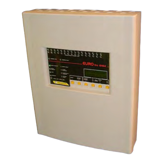
Page 3: Front Panel Layout And Led Indicators
Eurofire Front Panel Layout INDICATOR DETAILS GENERAL FIRE - Illuminates when the panel has detected a fire activation or the Evacuate button has been pressed. GENERAL FAULT - Illuminates if a fault has been detected. SUPPLY HEALTHY - Is Illuminated whilst power is being supplied to the control panel. SUPPLY FAULT - Is made to flash if there is a fault with either the power supply or standby battery system. - Page 4 Benefits can be seen with time saving, reduced wiring cost, and ease of installation. The Eurofire EN54 control panel is available as either 4, 8, 12 or 16 zones of fire cover. Other Eurofire EN54 panels and Repeaters can be networked using the ‘CAN Connect’ link.
-
Page 5: Panel Basics
Panel Basics The fire control panel is operated by the 6 buttons which are mounted below the LCD. In order to gain access to the fire panel functions, it is necessary to enter the 4 digit user code – this is to prevent unauthorised access. In order to enter the user code, the password screen must be activated. -
Page 6: User Menu Operation
User Menu Operation When entering the User menu system, the LCD should display as shown below:- 11 Evacuate →12 ------EXIT------ 13 Top of engineers Silence Up Pressing button 4 (UP) or button 5 (Down) will take you through the available USER options, these are:- 1 - Software Version - Shows the version of software that is controlling the Fire panel. -
Page 7: User Menu Functions
User Menu Functions → 1 SOFTWARE VERSION Top of users This shows the version and date of →SOFTWARE-x.x MAR 03 controlling software for the Eurofire fire SET CLOCK control panel. Silence Up → 2 SET CLOCK - This function sets the time and date of the panel. Set Clock Sets the Year. -
Page 8: Isolate Sounder
Set Clock Sets the Minutes. 14:21 Fri31 Oct 2003 Minutes = 21 Button 4- UP increases Minutes. Down Next Button 5- Down decreases Minutes. Button 6- Next Finishes setting clock and returns back to menu system. → 3 ISOLATE SOUNDER –... -
Page 9: Isolate Zone
If a zone is set as conventional – no zone powered sounders fitted:- Select Zone Sounder Button 3- Is Not available Zn 2 =conventional Button 4- Up increments to next zone. Button 5- Dwn decrements to previous exit zone. Button 6- exit returns to menu system. →... -
Page 10: Bell Test
→ 6 BELL TEST– Activates individual Alarm Lines. The selected alarm line is repeatedly switched on and off at a rate of 30 seconds until stopped. Note, An alarm line that is isolated cannot be tested. Bell 1 Test? Button 4- Test activates the Alarm Line at a rate of 30sec. -
Page 11: Event Log To Lcd
→ 9 EVENT LOG TO LCD – Allows the user to view the history of previous events. Upto 99 events with the time and date can be stored. The LCD will display the last/most recent event - given event no.1. New events are always given event no.1. Events are given numbers in ascending order to when they occurred from 1-most recent to 99-the oldest event. -
Page 12: Panel Operation
Panel Operation Normal Condition In the normal condition, the LCD will display:- EMERGI-LITE TnB Line 1- User Display Message. This is Scanning 16 Zones set on commissioning. 14:42 Thu 6 Nov 2003 Line 2- Displays the number of detection zones on the fire panel. Line 4- Displays Time. -
Page 13: Fault Condition
Fault Condition In a fault condition, the internal buzzer will sound and the ‘GENERAL FAULT’ LED will be illuminated. LED’s specific to the fault will be made flash. Devices connected to the fault relays will be triggered e.g. digital communicator. Eg. - Page 14 Aux 12V Fault Indicates that an Auxiliary 12V Output has failed. The cause of failure will need investigating and rectifying. Aux 24V Fault Indicates that an Auxiliary 24V Output has failed. The cause of failure will need investigating and rectifying. Earth Fault Indicates that a fault has occurred with the system earthing.
-
Page 15: Summary Of Maintenance Requirements Of Bs5839-1 : 2002
Summary of the Maintenance Requirements of BS5839-1: 2002 Note: This information is provided for the general guidance of fire detection and fire alarm system users. As it is a summary, it omits much of the information included in the clauses listed below. It is therefore not intended to be a replacement for the detailed recommendations included within BS5839-1. - Page 16 Clause 45.4 Inspection and Test of a System Over a 12 Month Period • The switch mechanism of every manual call point should be tested. • Every automatic fire detector should be examined and functionally tested. Note: this includes, but is not limited to;...
-
Page 17: System Log Book
SYSTEM LOG BOOK Date System Lamp Callpoint- Callpoint Battery Comments signed Healthy Test Sensor Check Used Test... -
Page 18: Engineers Manual
ENGINEERS MANUAL INTRODUCTION This manual provides the necessary guidance for the correct installation and commissioning of a ‘Eurofire’ control panel. Persons carrying out system design and installation should be familiar with the relevant code of practice relating to the installation of fire detection and alarm systems within buildings. The ‘Eurofire’ panel is an advanced fire detection system based on microprocessor control circuitry. -
Page 19: Installation Procedure
INSTALLATION PROCEDURE It is recommended that installation is delayed until all building or maintenance work has been completed. If building work is being carried out in the vicinity of the installation it may result in damage to the panel. Remove fire panel from its packing and retain the packing for storage of panel parts during installation. To remove the front –... - Page 20 Fig.1 CONVENTIONAL DETECTOR AND CALLPOINT WIRING Fig.2 ORBIS DETECTOR BASE WITH REMOTE LED MANUAL CALL POINT STANDARD BASE REMOTE LED L1 IN L1 IN BLACK L1 OUT END OF LINE L1 IN L1 IN COMPONENT BASE AT END OF LINE SOUNDER WITH BASE Fig.3 ALARM SENSE - 2 WIRE, WIRING DETAILS Fig.4 CONVENTIONAL SOUNDER WIRING...
- Page 21 Fig.5 4WAY AUXILIARY RELAY PCB WITH TWIN CONTROL CIRCUITS Fig.6 Class Change, Bomb Alert & Programmable I/P Fig.5 4WAY ALARM EXTENDER PCB...
-
Page 22: Panel Specification
PANEL SPECIFICATION Panel Order Code FEUN-4 FEUN-8 FEUN-12 FEUN-16 No. of Zones 4 Zone 8 Zone 12 Zone 16 Zone (25 detectors per zone max) conventional / conventional / conventional / conventional / 2wire 2wire 2wire 2wire No. of alarm lines 4 (expandable to 16 programmed in groups of 4) Maximum alarm load Total = 1.25A. - Page 23 INDICATORS:- 20*4 character LCD display. 16*Zone fire LED’s Common fire LED 16*Zone fault LED’s Common fault LED Supply Healthy LED Supply fault LED Delay Enabled LED Test LED Disabled LED Alarm silenced LED Alarm Fault / Disabled LED System fault LED CONTROLS:- Panel reset button Silence buzzer button...
-
Page 24: Engineering Mode
In order to gain access to the Engineers Switch to ON Functions, the ’Engr’s Switch’ must be switched to the ‘ON’ position. This is located on the Eurofire EN54 PCB. The front cover must be removed in order to access the switch. - Page 25 When engineers mode has been accessed, the initial entry point for the menu system is the same as that for the user. Engineers access allows you to scroll UP and DOWN through the menu system.. 11 Evacuate Engineers access allows you to scroll →12 ------EXIT------ UP and DWN through the menu options.
-
Page 26: Engineers Menu Functions
Engineers Menu Functions → 14 WLKTST ALL ZONES – Enables the user to test the fire detectors and call points on all zones of the fire alarm system. Walktesting Button 3- sndr selects whether or not to 16 of 16 zones activate the alarms when a device is Alarms to sound tested. - Page 27 Format of a pattern is shown below:- The overall period of operation for the pattern. It is given by setting Pattern time. Pattern time This can be to any time between 0-3600sec or until it is reset. Delay to Device Period over which Being Activated The devices will...
- Page 28 Pattern → Indicates that pattern details to be Alarms 1 2 3 4 Aux edited or viewed. →Pattern Details Button 3 Item, Moves →, to next line. Item Edit Exit Button 5 Edit, This will allow you to edit the details of pattern 0. Button 6 Exit, Exits from editing patterns.
- Page 29 For example, pattern 1 consisting of all alarms and Auxiliary relay is to be activated at another panel whose network address is no 2. The pattern should be alarms1,2,3&4 and auxiliary relay on until reset (one out-all out situation) without there being a delay to activation. Set pattern 1 and alter devices until Alarms 1, 2, 3, 4 and Aux.
-
Page 30: Assign Zone Patterns
This would be set up as shown:- NetAdd→ 4 Delay Pulse 90 On2 Off2 Netadd = network address No4 (where Pattern time 1890 the pattern will be activated.) Item Back Delay = 30 Seconds. Pulse time = 90 Seconds. (alarms will be pulsed for 90-30=60 sec) At a rate of :- On time = 2 sec Off time = 2sec. -
Page 31: Assign Class Change Pattern
→ 18 ASSIGN CLASS PAT – This assigns Class Change to a pattern. When Class Change is activated then the patterns assigned to it will operate. Set Class Patterns Shows that when class change is Pattern number activated Pattern 0 will Activate. ACTIVE toggle Pdwn... - Page 32 On entering option 23 SET ZONE CONFIG, the LCD will display the following menu. →Zn 1 =Conventional → Indicates which line of options is Fire type = 470 ohm being modified. Fire = Latching Toggle Item exit Button 3 – Toggle changes the setting of the line being modified.
-
Page 33: Enter Zone Text
To alter a Conventional zone in to a TwoWire (Alarm Sense) zone, for example Zone 2:- Remove Link J11 – This will ensure that the correct voltage is put on to the zone 2. Through option 23. → 23 SET ZONE CONFIG, Set the configuration of Zone 2 to TwoWire. If sounders have been installed onto the zone, alarm patterns will have to be created so that the sounders activate in a fire condition:- Through option 16 - →... -
Page 34: Edit User Text
It sends panel network address, zone no. if applicable, and also the nature of the fault. Eurofire EN54 repeaters The repeater gives all visual indications and allows control of a Eurofire EN54 control panel remotely - all user functions are available at the repeater. Contact Emergi-lite safety systems for more information. - Page 35 There are three methods of networking Eurofires and Repeaters together:- Star. Isostar - This is Isolated Star connection, using a network isolator card DualStar - This configuration, requires a network isolator card. With the DualStar, the network is wired as both Star and Isostar. Should a fault occur on any one set of the wiring, the network will still operate using the other set of wiring.
- Page 37 To set up a network:- 1) Ensure that the wiring of the network is correct, and the network terminators are correctly placed for the installation. 2 terminators must be present in the networked system – they must be placed on panels or repeaters that are at the two furthest points on the network.
- Page 39 Default Ptn, This can either be Active or Inactive only. OFF – Switched OFF The default pattern, if active, is one that if a fire signal is received from another Eurofire EN54 panel, all alarms and Star – Star mode. Isostar – Isolated Star mode using auxiliary relay are activated on this panel.
- Page 40 6 exit Returns to menu system saving all changes Devices seen on the network are shown as either P = Eurofire EN54 Panel or R = Eurofire EN54 Repeater, Their status is shown as Y=connected or N=not connected to this panel.
-
Page 41: Event Log To Pc
In ‘HyperTerminal’ choose the ‘Transfer’ tab and then select ‘Capture Text’, select a name and location where the file is to be saved. Once the PC is set up to receive data from the Eurofire EN54 panel Then select → 28 EVENT LOG TO PC The event log will now be sent to the PC. -
Page 42: Data Pc>Panel
1) Firstly set up the PC to Panel connection as shown above in ‘EVENT LOG TO PC’. 2) Select option → 29 DATA PC>PANEL – from the menu system of the Eurofire EN54. The Eurofire EN54 panel is now ready to received data from the PC, the LCD will show:-... -
Page 43: Zone Programming Sheet
EUROFIRE PROGRAMMING SHEET Customer:____________________________________ Site:_________________________________________ Commission Date:_____/_____/_____ Panel Serial No:__________________ ZONE PAT ZONE TEXT (20 characters) SYSTEM HEALTHY MESSAGE (20 Characters) -
Page 44: Pattern Programming Sheet
PATTERN PROGRAMMING The overall period of operation for the pattern. It is given by setting Pattern time. Pattern time This can be to any time between 0-3600sec or until it is reset. Delay to Device Period over which Being Activated The devices will Period over which the devices will be Activated. -
Page 45: Network Programming Sheet
NETWORK PROGRAMMING Type, P = Eurofire EN54 Panel, R = Eurofire EN54 Repeater Panel On/Off ADDR TYPE LOCATION TEXT (20 characters) - Page 46 NOTES...
- Page 47 NOTES...