Table of Contents
Advertisement
Quick Links
SIMATIC HMI
HMI device
IRD400
Operating Instructions
05/2018
A5E36790512-AC
___________________
Preface
___________________
Overview
___________________
Safety instructions
___________________
Installing and connecting the
display unit
___________________
Operating the display unit
___________________
Configuring the display unit
___________________
Maintenance and repairs
___________________
Technical specifications
___________________
Appendix
1
2
3
4
5
6
7
A
Advertisement
Table of Contents

Related Manuals for Siemens SIMATIC HMI IRD400


Summary of Contents for Siemens SIMATIC HMI IRD400
- Page 1 ___________________ Preface ___________________ Overview ___________________ SIMATIC HMI Safety instructions ___________________ Installing and connecting the display unit HMI device IRD400 ___________________ Operating the display unit ___________________ Configuring the display unit Operating Instructions ___________________ Maintenance and repairs ___________________ Technical specifications ___________________ Appendix 05/2018 A5E36790512-AC...
- Page 2 Note the following: WARNING Siemens products may only be used for the applications described in the catalog and in the relevant technical documentation. If products and components from other manufacturers are used, these must be recommended or approved by Siemens. Proper transport, storage, installation, assembly, commissioning, operation and maintenance are required to ensure that the products operate safely and without any problems.
-
Page 3: Preface
● Commissioning engineers ● Operators ● Maintenance personnel Scope This document applies to the display unit "SIMATIC HMI IRD400" with the article number 6ES7292-0AA50-1AA0. Note Note: • You are also going to need this document whenever the system is recommissioned. Keep this and supplementary documentation in a safe place for the entire life cycle of the device. - Page 4 A note contains important information about the product described in the document and its handling, or a specific section of the document to which you should pay particular attention. Naming conventions Term Applies to Display unit SIMATIC HMI IRD400 Device Display unit Control cabinet Installation cabinet •...
-
Page 5: Table Of Contents
Table of contents Preface ............................3 Overview ............................7 Product overview ......................... 7 Scope of delivery ......................... 7 Design of the display unit ..................... 8 Accessories ......................... 9 Safety instructions ........................10 Industrial Security ......................12 Installing and connecting the display unit ..................13 Preparing for mounting ...................... - Page 6 Table of contents Technical specifications ....................... 41 Certificates and approvals ....................41 Notes about usage ......................42 Electromagnetic compatibility .....................42 Ambient conditions ......................44 7.4.1 Transportation and storage requirements ................44 7.4.2 Operational requirements ....................45 7.4.3 Tests for ambient conditions ....................46 Dimensional diagram ......................47 Technical specifications ......................47 Interface description ......................49 7.7.1...
-
Page 7: Overview
Overview Product overview The display unit is used to display data which is sent by a controller. Digits or symbols can be shown in the display. The status of the controller, for example, can be signaled via the LEDs. In addition, two controllers which are each connected to a IRD400 display unit can communicate via the display units. -
Page 8: Design Of The Display Unit
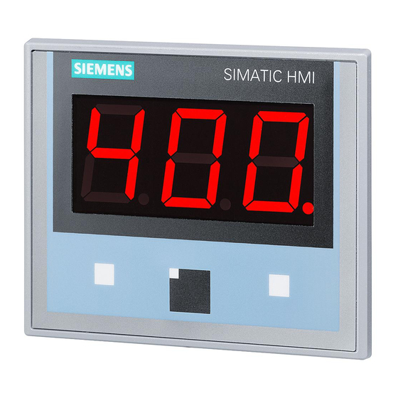
Overview 1.3 Design of the display unit Design of the display unit ① ⑥ PROFINET ports X1 P1 and X1 P2 Recesses for a mounting clip ② ⑦ Power supply connector X80 "Green" and "red" LEDs, for example for displaying the operating state ③... -
Page 9: Accessories
Accessories Accessories for the display unit: ● IR remote control The IR remote control represents the input device for the display unit. The article number is 6ES7292-0CA50-0AA0. Accessories can be found on the Internet (https://mall.industry.siemens.com). IRD400 Operating Instructions, 05/2018, A5E36790512-AC... -
Page 10: Safety Instructions
Safety instructions WARNING Injury or material damage You risk the development of danger sources and deactivation of safety functions if you neglect the safety and handling instructions provided in this document. This can result in personal injuries or material damage. Strictly adhere to the safety and handling instructions. - Page 11 Safety instructions These safety regulations are based on DIN VDE 0105. Note The safety regulations must be applied in the aforementioned order before any work is carried out on electrical systems. The safety regulations must be applied in reverse order on completion of all tasks on the electrical system.
-
Page 12: Industrial Security
In order to protect plants, systems, machines and networks against cyber threats, it is necessary to implement – and continuously maintain – a holistic, state-of-the-art industrial security concept. Siemens’ products and solutions only form one element of such a concept. Siemens’ products and solutions only form one element of such a concept. -
Page 13: Installing And Connecting The Display Unit
Damaged parts Do not install parts damaged during shipment. In the case of damaged parts, contact your Siemens representative. The package content is described in section Scope of delivery (Page 7). Keep the provided documentation in a safe place. The documentation is part of the HMI device and is required for subsequent commissioning. -
Page 14: Permitted Mounting Positions
Installing and connecting the display unit 3.1 Preparing for mounting 3.1.2 Permitted mounting positions Mounting position The display unit is approved for operation in horizontal and inclined mounting position in stationary and mobile control cubicles. The following lateral installation angles are permitted: Mounting position Deviation from the perpendicular axis Temperature... - Page 15 Installing and connecting the display unit 3.1 Preparing for mounting Mobile operation If you operate the device in a mobile system, for example in an electrical monorail system, then in addition to the lateral installation angle, the permitted tilt of the front of the device must be taken into consideration.
-
Page 16: Installation Location And Clearance
Installing and connecting the display unit 3.1 Preparing for mounting 3.1.3 Installation location and clearance Selecting installation location The display unit is designed for installation in a control cabinets. The display unit is installed in landscape format. NOTICE Installation location Non-compliance with permissible ambient conditions at the installation location may lead to malfunctions. - Page 17 Installing and connecting the display unit 3.1 Preparing for mounting Dimensions of the mounting cut-out The following figure shows the dimensions of the mounting cut-out and the clearances to be observed when mounting several devices in a horizontal or vertical arrangement. Configuration of the mounting cut-out The following conditions must be met to ensure the degree of protection: ●...
-
Page 18: Installing The Display Unit
Installing and connecting the display unit 3.2 Installing the display unit Installing the display unit The display unit is installed in a control cabinet with mounting clips. These prevent the main dimensions of the display unit from being exceeded. Always adhere to the specifications in these operating instructions when installing the display unit. -
Page 19: Connecting The Display Unit
Installing and connecting the display unit 3.3 Connecting the display unit Hook the mounting clip in the cutout as shown. The red markers indicate additional cutouts into which a mounting clamp is to be installed. Screw in the threaded pin until the gap between the enclosure front and the display unit is closed. -
Page 20: Connecting Functional Ground
Note You will risk malfunctions if using cables that are not approved. Always use shielded standard cables for data transmission. Orders for accessories can be placed at the following Internet URL: Industry Mall (https://mall.industry.siemens.com) 3.3.2 Connecting functional ground Potential differences Potential differences may develop between distributed plant parts. - Page 21 Installing and connecting the display unit 3.3 Connecting the display unit General requirements of equipotential bonding You must reduce potential differences to the possible minimum by installing equipotential conductors to ensure proper functioning of the respective electronic components. For this reason, observe the following rules when installing the equipotential bonding circuit: ●...
-
Page 22: Connecting The Power Supply
Installing and connecting the display unit 3.3 Connecting the display unit Cable shielding is not suitable for use as function ground. 3.3.3 Connecting the Power Supply Information about the power supply NOTICE Safe electrical isolation Use only 24 V DC power supply units with safe electrical isolation in accordance with IEC 60364-4-41 or HD 384.04.41 (VDE 0100, Part 410), for example, in accordance with the PELV standard. - Page 23 Installing and connecting the display unit 3.3 Connecting the display unit Wiring the mains terminal block The power supply terminal is contained in the accessory kit. The mains terminal is designed for lines with a cross-section of between 0.25 mm² and 2.5 mm². Note Connect solid or flexible cables with a cross-section ≥...
-
Page 24: Connecting The Plc
Always use only the approved cables to connect a SIMATIC S7 controller. Standard cables are available for the connection. You can find ordering information on the Internet (https://mall.industry.siemens.com). Connection diagram You can find additional information on the topology of PROFINET networks in the following... -
Page 25: Connecting Digital Inputs/Outputs
Installing and connecting the display unit 3.3 Connecting the display unit 3.3.5 Connecting digital inputs/outputs The I/O interface X10 with 8 digital inputs/outputs for input and output devices which are not to be operated in fail-safe mode are located on the side of the device. Unconnected inputs/outputs are automatically set to "0". -
Page 26: Operating The Display Unit
Operating the display unit Depending on the operating mode, the display unit is operated via the remote control or communicates with a different display unit of the same type via the infrared transmitter/receiver module. The operating mode is defined via the configuration. ●... - Page 27 Operating the display unit The following figure shows the opening angle and range of the transmission/receiving range of the display unit. The opening angle of the transmission/receiving range is ± 60°. The remote control signals can be received at a distance ≤ 10 m, but only if the default value for "Release Timeout" of 500 ms is set.
- Page 28 Operating the display unit Communication with a display unit of the same model In "IR P2P" operating mode, the display unit communicates with another display unit of the same type. Communication is performed by sending and receiving data packets. The configuration is used to control whether data packets are sent or received.
-
Page 29: Configuring The Display Unit
Configuring the display unit PROFINET modules You can find basic information about configuring PROFINET IO devices in the information system of STEP 7 (TIA Portal). In the configuration, PROFINET IO devices are installed in slots and sub-slots that are defined via modules and submodules. The communication interface between PROFINET IO device modules and submodules is defined by the GSDML file. -
Page 30: Configuring In The Tia Portal
Configuring the display unit 5.2 Configuring in the TIA Portal The following tables describe the PROFINET interfaces of each PROFINET module. The GSDML file is also structured based on this description The GSDML file contains additional details, for example, IO addresses. Configuring in the TIA Portal The following section briefly describes the configuration in TIA Portal. - Page 31 Configuring the display unit 5.2 Configuring in the TIA Portal Procedure 1. In the network view, establish a connection to the controller (see figure above). IRD400 Operating Instructions, 05/2018, A5E36790512-AC...
- Page 32 Configuring the display unit 5.2 Configuring in the TIA Portal 2. Click "Device Control_1" in the device view (see figure below). 3. Set the module parameters under "Properties > General". 4. Set the default value 500 ms as "IR-RC Release Timeout". IRD400 Operating Instructions, 05/2018, A5E36790512-AC...
-
Page 33: Slot 1 - Ir-Rc Module (Ir Remote Control)
Configuring the display unit 5.3 Slot 1 - IR-RC module (IR remote control) Slot 1 - IR-RC module (IR remote control) Slot 1 is used to define how the key signals of the IR remote control are transmitted to the controller. -
Page 34: Slot 2 - Display Module (7-Segment Display And Leds)
Configuring the display unit 5.4 Slot 2 - DISPLAY module (7-segment display and LEDs) Slot 2 - DISPLAY module (7-segment display and LEDs) Slot 2 is used to control the three 7-segment displays and the LEDs of the display unit. Parameter Bit coding Direction... - Page 35 Configuring the display unit 5.4 Slot 2 - DISPLAY module (7-segment display and LEDs) The following figure shows the bit coding of a 7-segment display. Examples: Binary code Hex code Symbol Bit position 0x3F "0." 0x06 "1" 0x5B "2" 0x4F "3"...
-
Page 36: Slot 3 - Digital Port Module (8 X Di/Do)
Configuring the display unit 5.5 Slot 3 - Digital port module (8 x DI/DO) Slot 3 - Digital port module (8 x DI/DO) Slot 3 is used to control the 8 digital inputs/outputs of the display unit. Parameter Bit coding Direction Data Size... -
Page 37: Slot 4 - Ir-P2P Module ("Ir-P2P" Operating Mode)
Configuring the display unit 5.6 Slot 4 - IR-P2P module ("IR-P2P" operating mode) In the engineering software, each digital input/output can be configured independently as an input or output. Note A configuration change requires a restart The configuration of the digital inputs/outputs cannot be changed during operation. The configuration must be changed and the device restarted. -
Page 38: Slot 5 - Control Module (Operating Mode)
Configuring the display unit 5.7 Slot 5 - Control module (operating mode) Slot 5 - Control module (operating mode) Slot 5 is used to control the operation mode of the display unit. Parameter Bit coding Direc- Data Size Index Init Description name communication... - Page 39 Configuring the display unit 5.7 Slot 5 - Control module (operating mode) The operating mode of the display unit is controlled via the CTRL_mode parameter. The display unit continuously informs the controller about the current status using the CTRL_stat signal, to enable the control program to respond to the status of the display unit. WARNING Only enable test mode for test purposes In test mode, functions are enabled which may not be used during operation.
-
Page 40: Maintenance And Repairs
Repairs The display unit will not be repaired. You can send a defective device to the Retouren- Center Fürth for error analysis . The address is: Siemens AG Division Digital Factory Retouren-Center Siemensstr. 2 90766 Fürth Germany You will receive a credit note for the return device. -
Page 41: Technical Specifications
Official Journals of the European Union: 2014/30/EU "Electromagnetic Compatibility Directive" (EMC Directive) EU Declaration of Conformity The EU Declarations of Conformity are available to the relevant authorities at the following address: Siemens AG Digital Factory Factory Automation DF FA SE Breslauer Str. 5 D-90766 Fürth... -
Page 42: Notes About Usage
Technical specifications 7.2 Notes about usage Notes about usage Industrial applications The device is designed for industrial use. It conforms to the following standards: ● Requirements for emissions EN 61000-6-4 ● Requirements for interference immunity EN 61000-6-2 Use in residential areas Note Device not intended for use in residential area The device is not suitable for use in residential areas. - Page 43 Technical specifications 7.3 Electromagnetic compatibility Disturbance EMC applies to the following disturbances: ● Pulse-shaped disturbance The following table shows the EMC of the device in terms of pulse shaped disturbance. Pulse-shaped disturbance Test value Corresponds to degree of severity Electrostatic discharge in accordance with Air discharge: 8 kV IEC 61000-4-2 Contact discharge: 6 kV...
-
Page 44: Ambient Conditions
Technical specifications 7.4 Ambient conditions RF interference emission The following table shows the unwanted emissions from electromagnetic fields in accordance with EN 61000-6-4/A1 (industrial area), measured at a distance of 10 m. Frequency Value 30 to 230 MHz < 40 dB (μV/m), quasi peak 230 to 1000 MHz <... -
Page 45: Operational Requirements
Technical specifications 7.4 Ambient conditions 7.4.2 Operational requirements The following table shows the permitted ambient conditions for the device. ● Mechanical ambient conditions Standard Title IEC 60721-3-3 Classification of environmental conditions – part 3: Classes of environmental factors and their limits, part3: Stationary use, weatherproof Class 3M3 ap- plies. -
Page 46: Tests For Ambient Conditions
Technical specifications 7.4 Ambient conditions 7.4.3 Tests for ambient conditions Tests with regard to mechanical ambient conditions The following table provides information on the type and scope of tests for mechanical ambient conditions performed for the device during operation. Test Physical variable Value, comment Vibrations in accordance with... -
Page 47: Dimensional Diagram
Technical specifications 7.5 Dimensional diagram Dimensional diagram Technical specifications Mechanical system Physical variable Value Dimensions 140 × 116 × 37.5 mm Weight ≤ 380 g Display type Three 7-segment displays LEDs for messages LED for IR send/receive signal IRD400 Operating Instructions, 05/2018, A5E36790512-AC... - Page 48 Technical specifications 7.6 Technical specifications Electrical system Physical variable Value Input voltage 24 V DC Voltage range, permitted +20.4 to +28.8 V (–15%, +20%) Current consumption, maximum 1.1 A Protection class, according to IEC/EN 61140 Degree of protection, front, according to IEC 60529 IP65 Degree of protection, rear, according to IEC 60529 IP20...
-
Page 49: Interface Description
Technical specifications 7.7 Interface description Infrared transmission/reception range Physical variable Value Opening angle ≤ 120° Range ≤ 10 m (remote control to display unit) ≤ 2 m (display unit to display unit) Wavelength 940 nm Input signal, necessary minimum duration ≥... -
Page 50: Profinet
Technical specifications 7.7 Interface description 7.7.3 PROFINET X1, RJ45 plug connector Assignment Tx– n. c. n. c. Rx– n. c. n. c. 7.7.4 Digital inputs/outputs X10, plug connector, 12-pin Assignment digital input/output 0 digital input/output 1 digital input/output 2 digital input/output 3 digital input/output 4 digital input/output 5 digital input/output 6... -
Page 51: Appendix
● Technical Support (https://support.industry.siemens.com) ● Support Request (http://www.siemens.com/automation/support-request) ● Service (http://support.automation.siemens.com/WW/view/en/16604318) ● Contacts and office locations (http://www.automation.siemens.com/mcms/aspa-db/en/Pages/default.aspx) ● Training center (http://sitrain.automation.siemens.com/sitrainworld/?AppLang=en) SIMATIC product information is available at: ● Industry Portal (http://www.automation.siemens.com/_en/portal/index.htm) ● Overall SIMATIC documentation (http://www.siemens.com/simatic-tech-doku-portal) IRD400 Operating Instructions, 05/2018, A5E36790512-AC... -
Page 52: Abbreviations
Appendix A.2 Abbreviations Abbreviations Alternating current Aktiengesellschaft Direct Current Deutsches Institut für Normung Europäische Gemeinschaft Components and modules endangered by electrostatic discharge Electrical Monorail System EMS400S Electric Monorail System 400 Signal Electromagnetic compatibility European standard Ground High Frequency International Electronic Commission Ingress Protection Infrared Information Technology... -
Page 53: Index
Index Ambient conditions EC Declaration of Conformity, 41 Operation, 45 Electrical system Transportation and storage, 44 Technical specifications, 48 Approval Emission, 42 CE, 41 ESD, 12 Cable Industry Portal, 51 Connecting, 20 Infrared transmission/reception range CE approval, 41 Technical specifications, 49 Checking Infrared transmitter/receiver module, 26 Package content, 13... - Page 54 Index Package content Wiring Checking, 13 Cable, 20 PELV, 22 Sequence, 19 Pin assignment Wiring sequence, 19 X1, 50 X10, 50 X30, 49 X80, 49 X1, 50 Potential difference, 20 X10, 50 PROFINET (LAN) X30, 49 Technical specifications, 48 X80, 49 Radiation, 11 High frequency radiation, 11 Radio interference, 42...