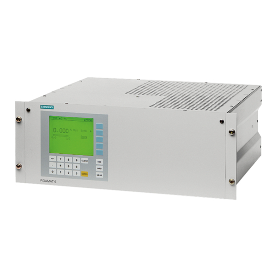
Siemens FIDAMAT 6 Operating Instructions Manual
Gas analyzer for determination of total hydrocarbon content
Hide thumbs
Also See for FIDAMAT 6:
- Operating instructions manual (118 pages) ,
- Operating instructions manual (202 pages) ,
- Compact operating instructions (37 pages)
Table of Contents
Advertisement
Quick Links
Advertisement
Table of Contents

Related Manuals for Siemens FIDAMAT 6


Summary of Contents for Siemens FIDAMAT 6
- Page 3 General information Description Installing and connecting Continuous Gas Analysis Commissioning Gas analyzer for determination of total hydrocarbon content Operation FIDAMAT 6 Functions Operating Instructions Service and maintenance Spare parts and accessories Technical specifications Dimensional drawings and circuit diagrams Appendix List of abbreviations...
- Page 4 Note the following: WARNING Siemens products may only be used for the applications described in the catalog and in the relevant technical documentation. If products and components from other manufacturers are used, these must be recommended or approved by Siemens. Proper transport, storage, installation, assembly, commissioning, operation and maintenance are required to ensure that the products operate safely and without any problems.
-
Page 5: Table Of Contents
2.1.3 Main features .......................... 13 Design ............................. 14 Control panel and communication ..................16 Method of operation ........................ 19 Gas flow of the FIDAMAT 6-E ....................21 Communication ........................21 2.6.1 General information ........................ 21 2.6.2 ELAN interface ........................22 2.6.3... - Page 6 Safety information ........................41 Preparation for commissioning ....................43 4.2.1 General information for commissioning ................. 43 4.2.2 Information on commissioning the FIDAMAT 6 ..............43 4.2.3 Checking for leaks ......................... 44 Commissioning and operation ....................45 4.3.1 Warm-up phase and operating states ..................46 4.3.2...
- Page 7 Replacement of motherboard and optional board ..............126 7.1.3 Replacement of mains fuses ....................127 7.1.4 Replacement of thermal fuse ....................128 Cleaning the device ......................129 Maintenance request and fault message ................129 FIDAMAT 6 Operating Instructions, 03/2018, A5E00222135-03...
- Page 8 8.2.3 Device views with spare part numbers ................144 Technical specifications ........................149 General technical data of the FIDAMAT 6 gas analyzers ............ 149 Technical specifications of the FIDAMAT 6E ............... 151 Dimensional drawings and circuit diagrams ..................153 10.1 Motherboard pin assignments ....................
-
Page 9: General Information
For further information, or in the case of problems which are not covered in enough detail in this document, please request the required information from your local or responsible Siemens regional office. Note In particular, before using the device for new research and development applications, we recommend that you first contact us to discuss the application in question. -
Page 10: Use Of These Operating Instructions
This manual applies solely to the version of the device stated above. This version of the FIDAMAT 6 will be referred to in the following as the FIDAMAT 6-E. However, where features or procedures are described that apply to all versions of the FIDAMAT 6 series, the standard name FIDAMAT 6 will be used. -
Page 11: Warranty Conditions
All obligations on the part of Siemens AG are contained in the respective sales contract, which also contains the complete and solely applicable liability provisions. The provisions defined in the sales contract for the responsibility for defects are neither extended nor limited by the remarks in this document. -
Page 12: Year Of Manufacture
Federal Republic of Germany are valid. When this product is used beyond the scope of these standards and regulations, the valid standards and regulations of the country of the operating company apply. FIDAMAT 6 Operating Instructions, 03/2018, A5E00222135-03... -
Page 13: Description
The FIDAMAT 6 analyzer is intended for continuous operation. Frequent switching on and off (e.g. daily) can negatively affect the service life of the ignition device and pilot light. - Page 14 Measurement in flue gases according to 13th/17th BlmSchV and TA Luft for fuel types oil, coal, gas and waste. Furthermore, the TÜV-approved versions of the FIDAMAT 6 comply with the requirements of EN 14956 and QAL 1 according to EN 14181. Conformity of the devices with both standards is TÜV-certified.
-
Page 15: Certified Operation For Emission Monitoring According To En 15267-3
● Electrically isolated measured value output ● External pressure sensor can be connected for correction of process gas pressure fluctuations ● Easy device replacement since electrical connections of the device can be easily disconnected FIDAMAT 6 Operating Instructions, 03/2018, A5E00222135-03... -
Page 16: Design
● No clogging in the sample gas capillary tube thanks to the use of a quartz capillary tube ● Wear-free, corrosion-proof filter ● Required combustion gas: hydrogen (H Design Design of the entire device The FIDAMAT 6 is made up of two main groups: a) Electronics b) Analyzer section a) Electronics This comprises: ●... - Page 17 FID housing Stainless steel 1.4571 Design of the FIDAMAT 6 enclosure ● 19" rack unit with 4 height units for installation in swivel frame ● 19" rack unit with 4 height units for installation in cabinets, with telescopic or support rails ●...
-
Page 18: Control Panel And Communication
● Menu-driven operation for parameter assignment, test functions and calibration ● User help in plain text ● Graphical display of the concentration curve; time intervals can be configured ● Bilingual operating software: – German/English – English/Spanish – French/English – Spanish/English – Italian/English FIDAMAT 6 Operating Instructions, 03/2018, A5E00222135-03... - Page 19 11 Display of activated measuring ranges with marking of the current range 5 Measured value 12 Numeric keypad 6 Status message 13 Function keypad 7 Status line Figure 2-1 Measured value display and operator panel FIDAMAT 6 Operating Instructions, 03/2018, A5E00222135-03...
- Page 20 Options: ● Converter to RS 232 (for ELAN) ● Converter to TCP/IP Ethernet (for ELAN) ● Integration into networks via PROFIBUS DP/PA interface ● SIPROM GA software as service and maintenance tool (for ELAN) FIDAMAT 6 Operating Instructions, 03/2018, A5E00222135-03...
-
Page 21: Method Of Operation
The resulting amperage is a measure of the number of carbon atoms. The FIDAMAT 6 measures specific to the substance class, not component-specific. It measures the total of all organically bound carbons in a sample gas, however with different weighting of the hydrocarbon molecules. - Page 22 Description 2.4 Method of operation The sample gas is drawn into the FIDAMAT 6-E by means of the integrated diaphragm pump and is carried under overpressure over a heated line and an additional filter. It arrives at the flame ionization detector via a clog-proof fused silica restrictor. The hydrocarbons contained in the sample gas are combusted in an oxyhydrogen gas flame in the detector.
-
Page 23: Gas Flow Of The Fidamat 6-E
Description 2.5 Gas flow of the FIDAMAT 6-E Gas flow of the FIDAMAT 6-E Figure 2-3 Gas flow of FIDAMAT 6-E Communication 2.6.1 General information This device provides the following communication options: ● ELAN interface (RS485) ● SIPROM GA ● PROFIBUS DP/PA ●... -
Page 24: Elan Interface
RS485 to RS232/USB/Ethernet converter with connecting cable RS485 bus connector with jumper Analyzer RS485 cable RS485 bus connector RS485 network 9-pin Sub-D plug Optional: RS485 repeater Figure 2-4 Typical structure of an ELAN network (RS485) FIDAMAT 6 Operating Instructions, 03/2018, A5E00222135-03... - Page 25 6ES7972-0AA02-0XA0 All converters are delivered with a driver CD which also contains the SIPROM GA software. Further information can be found in the ELAN interface description: Article numbers: ● C79000-B5200-C176 German ● C79000-B5276-C176 English FIDAMAT 6 Operating Instructions, 03/2018, A5E00222135-03...
-
Page 26: Siprom Ga
Software requirements: ● Windows XP ● Windows 7 ● Windows 10 The SIPROM GA software is available on the Internet and can be downloaded from the following address: SIPROM GA download (http://support.automation.siemens.com/WW/llisapi.dll?aktprim=0&lang=en&referer=%2fWW %2f&func=cslib.csinfo&siteid=csius&groupid=4000002&extranet=standard&viewreg=WW&n odeid0=10806991&objaction=csopen) FIDAMAT 6 Operating Instructions, 03/2018, A5E00222135-03... -
Page 27: Upgrading Options
Description 2.6 Communication 2.6.3.2 Upgrading options You can order the current device firmware as a chip set with the following order numbers: Firmware upgrades for older analyzers Article No. FIDAMAT 6 German A5E00223093 English A5E00223146 French A5E00223149 Spanish A5E00223152 Italian A5E00223155 ULTRAMAT 6 (prior to SW version 4.1) -
Page 28: Profibus Dp/Pa
2.6.4 PROFIBUS DP/PA PROFIBUS DP/PA is the leading fieldbus on the market. All Siemens gas analyzers with an optional – also retrofittable – plug-in card are Profibus-compatible and comply with the binding "Device profile for analyzers" defined by the PNO (PROFIBUS International). Central access to the system analyzers is possible with the SIMATIC PDM software tool. - Page 29 Description 2.6 Communication All gas analyzers of Series 6 (ULTRAMAT 6, OXYMAT 6/61/64, CALOMAT 6/62 and FIDAMAT 6 as well as ULTRAMAT 23) are PROFIBUS-compatible with an optional plug-in card, which can also be retrofitted. Figure 2-5 Typical structure of a PROFIBUS system...
- Page 30 Description 2.6 Communication FIDAMAT 6 Operating Instructions, 03/2018, A5E00222135-03...
-
Page 31: Installing And Connecting
DANGER Danger of explosion The FIDAMAT 6 gas analyzer must not be used to measure mixtures that are ignitable in normal operation. If the device is to be used to measure flammable gases that can combine with air or oxygen to form an ignitable mixture, special measures must be taken to provide... -
Page 32: Installation Requirements
If a natural air exchange with the environment of the housing is ensured, there is no need to purge the housing of the FIDAMAT 6. The air exchange must be taken into consideration in particular when the device is installed in cabinets. -
Page 33: Installation Location Requirements
NOTICE Inadequate installation If you install the FIDAMAT 6 in a cabinet or a table housing, it is not enough to attach the device on the front side only, because the stress on the housing by the device's own weight will be too high. -
Page 34: Installation Requirements - Fidamat 6 Devices
Installation requirements - FIDAMAT 6 devices Maintenance Check all device components for electrical safety and proper operation on a regular basis. Have the FIDAMAT 6 undergo an annual maintenance. Especially check the leak-tightness of the gas path within the device (containment system). Note Always perform a leak test after service work on the containment system. - Page 35 Always perform a leak test after service work on the containment system. Pressure sensors The FIDAMAT 6 has two internal pressure sensors for measuring the sample gas pressure (= combustion air pressure) and the combustion gas pressure. Sample gas line For the gas supply and discharge lines, there is one directly heated inlet (sample) and one directly heated outlet each.
-
Page 36: Gas Preparation
The pressure of the zero gas and calibration gas is 3000 hPa. Higher pressure will result in increased gas consumption, while lower pressure may result in an incorrect calibration because sample gas can additionally be drawn in. FIDAMAT 6 Operating Instructions, 03/2018, A5E00222135-03... -
Page 37: Electrical Connection
● Provide a power disconnection device in the direct vicinity of the device (for load rating, see rating plate). It must be readily accessible and marked. ● Check whether the available line voltage agrees with that specified on the rating plate. FIDAMAT 6 Operating Instructions, 03/2018, A5E00222135-03... -
Page 38: Connection Of The Signal Lines
The core cross-section must be ≥ 0.5 mm². We recommend cables of type JE-LiYCY...BD. The cable length of the analog output depends on the load. See also Plug connector assignment of the optional board and PROFIBUS (Page 38) FIDAMAT 6 Operating Instructions, 03/2018, A5E00222135-03... -
Page 39: Circuit Diagrams (Pin Assignment)
Installing and connecting 3.4 Electrical connection 3.4.3 Circuit diagrams (pin assignment) 3.4.3.1 Motherboard pin assignments Figure 3-2 Motherboard pin assignment FIDAMAT 6 Operating Instructions, 03/2018, A5E00222135-03... -
Page 40: Plug Connector Assignment Of The Optional Board And Profibus
Installing and connecting 3.4 Electrical connection 3.4.3.2 Plug connector assignment of the optional board and PROFIBUS Figure 3-3 FIDAMAT 6, 19” rack unit, pin assignments on the optional board and PROFIBUS plug connector FIDAMAT 6 Operating Instructions, 03/2018, A5E00222135-03... -
Page 41: Elan Interface Cable
9 in the first and last connectors of a bus line (see figure "Pin assignments"). Note For a conductor length longer than 500 m or with high interferences, we recommend that a repeater be installed. For additional information, please refer to the ELAN interface description. FIDAMAT 6 Operating Instructions, 03/2018, A5E00222135-03... - Page 42 Installing and connecting 3.4 Electrical connection Order Nos.: ● C79000-B5200-C176 German ● C79000-B5276-C176 English Figure 3-4 Pin assignments See also ELAN configuration (function 73) (Page 106) FIDAMAT 6 Operating Instructions, 03/2018, A5E00222135-03...
-
Page 43: Commissioning
DANGER Danger of explosion The FIDAMAT 6 gas analyzer must not be used to measure mixtures that are ignitable in normal operation. If the device is to be used to measure flammable gases that can combine with air or oxygen to form an ignitable mixture, special measures must be taken to provide... - Page 44 If a natural air exchange with the environment of the housing is ensured, there is no need to purge the housing of the FIDAMAT 6. The air exchange must be taken into consideration in particular when the device is installed in cabinets.
-
Page 45: Preparation For Commissioning
Preparation for commissioning 4.2.1 General information for commissioning Device position The FIDAMAT 6 may only be operated in a horizontal position. Operation Before connecting and switching on the device, the operator must have made himself familiar with the device operation. -
Page 46: Checking For Leaks
During the measurement, the gas path, including the FID, must have a constant temperature. Test conditions: The specified pressures are relative pressures. Calibration gas: Synthetic air (sample gas path must not be contaminated) Test pressure: Operating pressure x 1.5 (operating pressure = 500 hPa) FIDAMAT 6 Operating Instructions, 03/2018, A5E00222135-03... -
Page 47: Commissioning And Operation
A warm-up phase of approximately one hour must be allowed to elapse after switching on. To prevent blocking the automatic warm-up process, the device must always be in measuring state. The current operating state can be read in the bottom line. FIDAMAT 6 Operating Instructions, 03/2018, A5E00222135-03... -
Page 48: Warm-Up Phase And Operating States
When the device has detected that the flame is burning, the built-in pump is switched on and the analyzer is set to "Measuring" operating state. During the warm-up phase, "WARMUP" appears in the bottom line of the measured value display, alternately with the current warm-up step. FIDAMAT 6 Operating Instructions, 03/2018, A5E00222135-03... - Page 49 Commissioning 4.3 Commissioning and operation Device operating states Figure 4-1 Operating states of the FIDAMAT 6 A change of state takes place using function 91, if required, or automatically as a result of faults / maintenance requests. FIDAMAT 6 Operating Instructions, 03/2018, A5E00222135-03...
-
Page 50: State Change Due To Fault / Maintenance Request
W9: External maintenance request - - - W10: AUTOCAL check deviation - - - After you have eliminated the cause of a maintenance request or fault, exit the current operating state using function 91. FIDAMAT 6 Operating Instructions, 03/2018, A5E00222135-03... -
Page 51: Measuring Ranges
F = (full-scale value of smallest measuring range) / (full-scale value of smallest measuring range - start-of-scale value) . "F" should not exceed a value of "7" here. In general, we recommend that the smallest span not be increased by more than approximately 30%. FIDAMAT 6 Operating Instructions, 03/2018, A5E00222135-03... - Page 52 The measuring range must not fall below the smallest measuring range (according to the rating plate), since in this case the noise and temperature influences on the measured value will increase relative to the measuring range, which would impair repeatability and worsen the drift behavior. FIDAMAT 6 Operating Instructions, 03/2018, A5E00222135-03...
-
Page 53: Calibration
Zero and span calibrations Connect the device to zero gas or calibration gas. In doing so, observe the prescribed input pressures. Calibrate the zero point using function 20, and the span using function 21. FIDAMAT 6 Operating Instructions, 03/2018, A5E00222135-03... -
Page 54: Calibration Examples
0 ppm C3 Span: 30 ppm C3 30 ppm C3 Calibrate the zero point Calibrating the span Note The operator input options of the named functions are described in detail in "Functions". FIDAMAT 6 Operating Instructions, 03/2018, A5E00222135-03... -
Page 55: Operation
11 Display of activated measuring ranges with marking of the current range 5 Measured value 12 Numeric keypad 6 Status message 13 Function keypad 7 Status line Figure 5-1 Measured value display and operator panel FIDAMAT 6 Operating Instructions, 03/2018, A5E00222135-03... - Page 56 ■ = activated (ON state; also in status message in the status line) □ = deactivated (OFF state; also in status message in the status line) ► = access a submenu/subfunction ● = initiate a function/subfunction (e.g. Start calibration...) FIDAMAT 6 Operating Instructions, 03/2018, A5E00222135-03...
- Page 57 Operation 5.1 General information about operation Device operating modes Table 5- 2 Operating modes of the FIDAMAT 6 Mode Properties Remarks Coded display mode The device only supplies relia- Measured value display is shown • ble measured values in this Protected submenus can only be •...
- Page 58 Operation 5.1 General information about operation Schematic diagram of the operating sequence with operating modes Figure 5-2 Operating sequence with operating modes FIDAMAT 6 Operating Instructions, 03/2018, A5E00222135-03...
-
Page 59: Measured Value Display
On the right side of the measured value display is the measured component with an arrow pointing to the right (►). A softkey is assigned to this component. Press this softkey to call the main menu. See also General information about operation (Page 53) FIDAMAT 6 Operating Instructions, 03/2018, A5E00222135-03... -
Page 60: Entering A Submenu
Decoding also activates the measured value memory, providing you have parameterized it using function 77. The coding status of the device can be read in the status line of the measured value display as a symbol "■ CODE" for "coded" or "□ CODE" for "decoded". FIDAMAT 6 Operating Instructions, 03/2018, A5E00222135-03... -
Page 61: Jump Back To Coded/Decoded Display Mode
Coding the device After jumping back to "Decoded display mode" with [ESC] or [MEAS], if you press [MEAS] again you put the device back into "Coded display mode". Only now is the functional check deactivated again. FIDAMAT 6 Operating Instructions, 03/2018, A5E00222135-03... -
Page 62: Fast Function Selection
2. Press the softkey of the component with the arrow ►. If the desired function is protected by a code, you will be asked to enter the code. See also Overview of operating functions (Page 61) FIDAMAT 6 Operating Instructions, 03/2018, A5E00222135-03... -
Page 63: Functions
Range selection (code 1) Define meas. ranges Parameters (code 1) El. time constants Limits On/off configuration Status messages G. signal display Select digits LCD contrast Ignite flame Date/Time Sample selection Setup logbook Int. valves FIDAMAT 6 Operating Instructions, 03/2018, A5E00222135-03... - Page 64 Analyzer test Select language Interfer. correct. Switch valves Lin. temp. comp. Error On/Off PROFIBUS config. (only with option board) Start-up state (operating states) Pressure values Dimension Factory settings See also Fast function selection (Page 60) FIDAMAT 6 Operating Instructions, 03/2018, A5E00222135-03...
-
Page 65: Analyzer Status
Indication of date of manufacture and device serial number ● Object version: Indication of the hardware design of the device ● Software version/date: Version of the motherboard software; date, version of boot software of motherboard FIDAMAT 6 Operating Instructions, 03/2018, A5E00222135-03... -
Page 66: Diagnostic Values (Function 2)
In case of servicing, function 110 (diagnostics service) is to be observed as well. However, this function is only accessible to service engineers. See also Logbook settings (function 60) (Page 93) Error on/off (function 87) (Page 119) List of maintenance requests (Page 131) List of faults (Page 133) FIDAMAT 6 Operating Instructions, 03/2018, A5E00222135-03... -
Page 67: Display Measuring Ranges (Function 4)
This menu is protected by the code of code level 1. The FIDAMAT 6 offers the option of a manual or automatic calibration (function 24). The latter is only possible with an optional board which contains an additional eight binary outputs and eight relay outputs. -
Page 68: Zero Calibration (Function 20)
Only initiate calibration when the measured value (actual value) has stabilized after feeding the zero gas. Otherwise, the calibration may be imprecise. If there is a lot of noise, increase the time constant before calibrating (function 50). See also Electric time constants (function 50) (Page 82) FIDAMAT 6 Operating Instructions, 03/2018, A5E00222135-03... -
Page 69: Span Calibration (Function 21)
When the actual value has stabilized, you can initiate the calibration by pressing the fourth softkey. The actual value is now made to agree with the setpoint. If you make a mistake during the calibration (e.g. wrong calibration gas), reload the original calibration by pressing the "CANCEL" softkey. FIDAMAT 6 Operating Instructions, 03/2018, A5E00222135-03... -
Page 70: Setting The Setpoints (Function 22)
The function screen shows the setpoint input with total calibration. The fourth measuring range is chosen here as the leading measuring range. With single calibration, there is no choice for the leading measuring range. FIDAMAT 6 Operating Instructions, 03/2018, A5E00222135-03... -
Page 71: Total / Single Calibration (Function 23)
(option board). If this is not the case, a corresponding message will appear on the display when the Autocal function is called. Automatic calibration can only be started when the device is in "Measuring" operating state! Figure 6-8 Autocal function FIDAMAT 6 Operating Instructions, 03/2018, A5E00222135-03... - Page 72 Rather, the differences are merely checked for selectable calibration tolerances. "Start autocal/-check via binary input": If you previously configured a binary input using function 72, you can initiate Autocal via a binary input. FIDAMAT 6 Operating Instructions, 03/2018, A5E00222135-03...
- Page 73 Sample gas intermediate operation can be necessary if the system may only leave measuring mode for a certain time. If the required purge times are greater in total than the permissible downtime, measuring mode must be returned to between calibrations. FIDAMAT 6 Operating Instructions, 03/2018, A5E00222135-03...
- Page 74 9. Short-term signaling contact in order to be able to start AUTOCAL on another device or channel. The specified Autocal sequence is shown in the following function displays. Figure 6-11 Example of Autocal sequence FIDAMAT 6 Operating Instructions, 03/2018, A5E00222135-03...
- Page 75 Functions 6.3 Calibration Figure 6-12 Example of Autocal sequence Figure 6-13 Example of Autocal sequence List for the AUTOCAL sequence: Note Zero gas 2 is not used with FIDAMAT 6. FIDAMAT 6 Operating Instructions, 03/2018, A5E00222135-03...
- Page 76 > 1. Note As long as Autocal is activated (Autocal ■), access to functions 20 and 21 is blocked. If you activate these functions anyway, a corresponding message appears on the display. FIDAMAT 6 Operating Instructions, 03/2018, A5E00222135-03...
- Page 77 – Via binary input – Via cycle "Autocal/-check sequence" 2. The device executes a sequence as configured in the subfunction. See also Relay outputs (function 71) (Page 96) Binary inputs (function 72) (Page 98) FIDAMAT 6 Operating Instructions, 03/2018, A5E00222135-03...
-
Page 78: Drift Values (Function 25)
The drift values can reset to 0.0 with the 'Reset drift values' instruction. When you reboot the device all measuring ranges have 0.0 as the drift value. FIDAMAT 6 Operating Instructions, 03/2018, A5E00222135-03... -
Page 79: Measuring Ranges
● At least two measuring ranges must be available. One measuring range is said to be present when the following is true: Measuring range start-of-scale value ≠ full-scale value ● The spans must become greater ● The measuring ranges must "border on" each other or overlap FIDAMAT 6 Operating Instructions, 03/2018, A5E00222135-03... - Page 80 Figure 6-19 Measuring range type A Start of measuring range End of measuring range Lower switchover point: select the smaller measuring range Upper switchover point: select the larger measuring range FIDAMAT 6 Operating Instructions, 03/2018, A5E00222135-03...
- Page 81 End of measuring range Lower switchover point: select the smaller measuring range Upper switchover point: select the larger measuring range The following applies to measuring range switching: Figure 6-22 Measuring range switch, type B FIDAMAT 6 Operating Instructions, 03/2018, A5E00222135-03...
-
Page 82: Define Measuring Ranges (Function 41)
(20 mA) of the analog output. If the message "Measuring ranges not plausible!" appears, this means that autoranging is not possible. If the start-of-scale and full-scale values are "0", the measuring range is deactivated. FIDAMAT 6 Operating Instructions, 03/2018, A5E00222135-03... -
Page 83: Parameters
The parameters menu contains all functions which are required for parameterizing the device. You can branch to further parameter functions by pressing the fifth softkey, "...continue". This menu is protected by the code of code level 1. FIDAMAT 6 Operating Instructions, 03/2018, A5E00222135-03... -
Page 84: Electric Time Constants (Function 50)
"ti" and "ta". By cleverly combining these three parameters, you can achieve a low display delay (90% time) despite high noise suppression. The effect on the set attenuation parameters can be observed in the bottom line. The "live" measured value is displayed here. FIDAMAT 6 Operating Instructions, 03/2018, A5E00222135-03... -
Page 85: Limits (Function 51)
"Limit…" You can change to the next limit using the fifth softkey ( See also Logbook (function 3) (Page 64) On/off functions (function 52) (Page 84) Relay outputs (function 71) (Page 96) FIDAMAT 6 Operating Instructions, 03/2018, A5E00222135-03... -
Page 86: On/Off Functions (Function 52)
For better orientation, the function numbers have also been specified. Activated functions are marked by "■", deactivated ones by "□". Using the fifth softkey ("...continue"), jump to the next function screen with further functions. FIDAMAT 6 Operating Instructions, 03/2018, A5E00222135-03... - Page 87 Besides the functions listed in the table "Functions switched on/off by function 52", function 52 can also be used to activate other service functions. These are restricted to service engineers and are only visible when the service code is entered (code level 3). FIDAMAT 6 Operating Instructions, 03/2018, A5E00222135-03...
-
Page 88: Status Messages (Function 53)
If you have configured the analog output with "Store on" under function 77, this remains in fault current state until you remove it because any code level has to be exited. FIDAMAT 6 Operating Instructions, 03/2018, A5E00222135-03... - Page 89 In addition, when communication is over the ELAN interface, the message "Remote" is displayed – also alternating – with display of the device status. See also Select measuring ranges (function 40) (Page 77) Limits (function 51) (Page 83) Analog output memory (function 77) (Page 110) FIDAMAT 6 Operating Instructions, 03/2018, A5E00222135-03...
-
Page 90: Graphical Representation Of Measured Values (Function 54)
Select the desired time period with softkey 1 or 2. The device now graphs the measured value vs. time: Figure 6-30 Measured value trend The most recent measured value is on the time axis at the left at t = 0. FIDAMAT 6 Operating Instructions, 03/2018, A5E00222135-03... -
Page 91: Measured Value Display (Function 55)
With the softkeys 3 and 4, you can choose the total number of digits and the maximum number of decimal places. Note that a maximum of five digits can be displayed (decimal point also counts as one digit). FIDAMAT 6 Operating Instructions, 03/2018, A5E00222135-03... -
Page 92: Lcd Contrast (Function 56)
For checking/testing purposes, you can also ignite the flame manually using function 57. Press the second softkey to activate ("■") or deactivate ("□") the ignition. The display shows the temperature of the flame and the measured current. FIDAMAT 6 Operating Instructions, 03/2018, A5E00222135-03... -
Page 93: Date/Time (Function 58)
Press the third softkey in order to accept the set data. These then appear at the bottom edge of the display. See also Logbook (function 3) (Page 64) Logbook settings (function 60) (Page 93) FIDAMAT 6 Operating Instructions, 03/2018, A5E00222135-03... -
Page 94: Measuring Point Switching (Function 59)
You can allocate a signal relay to each measuring point relay. This allows measuring point identification separate from the measuring point relay. Configure the signal relay, also using function 71. See also Relay outputs (function 71) (Page 96) FIDAMAT 6 Operating Instructions, 03/2018, A5E00222135-03... -
Page 95: Logbook Settings (Function 60)
With this function, you switch the internal valves for controlling the gases. Press the respective softkey to activate ("■") or deactivate ("□") the valves. The internal valves block or open the gas flow for combustion gas, combustion air, zero gas, calibration gas and sample gas. FIDAMAT 6 Operating Instructions, 03/2018, A5E00222135-03... -
Page 96: Configuration
All functions of this menu are only accessible via the code of level 2. This menu contains all functions required for configuring the device. Press the fifth softkey ("...continue") to branch to further configuration functions. FIDAMAT 6 Operating Instructions, 03/2018, A5E00222135-03... -
Page 97: Analog Output (Function 70)
4 – 20 4 – 20 (NAMUR) 20.5 21.5 Note If the electronics is defective, it is possible for the analog output to become stuck at approx. - 1 mA or approx. +24 mA. FIDAMAT 6 Operating Instructions, 03/2018, A5E00222135-03... -
Page 98: Relay Outputs (Function 71)
The connection assignments for the individual relays in the zero-current state can be found in the terminal diagram "Motherboard pin assignment". The relays are preset at delivery. Press the fifth softkey ("...cont."), to access the next function screen, thus branching to further relays. FIDAMAT 6 Operating Instructions, 03/2018, A5E00222135-03... - Page 99 Combustion gas valve is Actuation of valves open Combustion air Combustion air valve is Actuation of valves open Operator input Operator intervention Gas connection faulty; prompt required W5 (combustion air/combustion gas) present; Device in PAUSE / STANDBY FIDAMAT 6 Operating Instructions, 03/2018, A5E00222135-03...
-
Page 100: Binary Inputs (Function 72)
If you deactivate the "NAMUR" ("□") operating mode, the binary inputs behave compatibly with the software releases of the older version V 4.3.0 (marked with "X" in table "Control functions of the binary inputs"). FIDAMAT 6 Operating Instructions, 03/2018, A5E00222135-03... - Page 101 Make sure you save every change in the configuration of the binary inputs in the user data memory using function 75! If you neglect to do this, there is a danger that a previous (unwanted) configuration will be loaded by "Load user data" (function 75). FIDAMAT 6 Operating Instructions, 03/2018, A5E00222135-03...
- Page 102 N, X Note: Effective control only possible in "Measuring" and "Cali- brating" operating states! For FIDAMAT 6-G, also from "Standby", whereby the device requires a short time to build up pressure. Relay must be configured for sample gas. Before the sample gas valve opens, the other valves are closed.
- Page 103 N, X Sets the "Standby" start-up state (Function 91). This al- lows the sample gas pump to be switched off. Only valid for FIDAMAT 6-E (with pump) firmware version V1.3.5 or higher. See also Binary inputs (function 72) (Page 98)
- Page 104 3. Now set the "Zero Calib." binary input with the necessary voltage for at least 1 second. The device calibrates the zero point. Afterwards, it leaves the "Calibrating" operating state" ("□ CAL") and deactivates the "Function control" ("□ CTRL"). It is now back in "Measuring" state. Calibration is complete. FIDAMAT 6 Operating Instructions, 03/2018, A5E00222135-03...
- Page 105 3. Assign a binary input with the "Calibration gas" function (function 72). 4. Assign a binary input with the "Span Calib." function for calibrating the span. FIDAMAT 6 Operating Instructions, 03/2018, A5E00222135-03...
- Page 106 5. Now set the binary input that you assigned to the desired measuring range after calibration for at least 1 second. The device is now in the desired measuring range. You can continue with measurement. FIDAMAT 6 Operating Instructions, 03/2018, A5E00222135-03...
- Page 107 The following figure illustrates the sequence: Figure 6-45 Calibration of the span via binary inputs See also Select measuring ranges (function 40) (Page 77) Relay outputs (function 71) (Page 96) Binary inputs (function 72) (Page 98) FIDAMAT 6 Operating Instructions, 03/2018, A5E00222135-03...
-
Page 108: Elan Configuration (Function 73)
Display of the tag assigned for this device in the ELAN network. Further ELAN details can be found in the ELAN interface description: ● (C79000-B5200-C176 German) ● (C79000-B5276-C176 English) See also ELAN interface cable (Page 39) FIDAMAT 6 Operating Instructions, 03/2018, A5E00222135-03... -
Page 109: Reset (Function 74)
, to load the last user data saved. These functions are important when the device is undergoing repairs or maintenance work, or, for example, if new parameter settings are to be tried out. Press softkey 3 to re-establish the factory settings. FIDAMAT 6 Operating Instructions, 03/2018, A5E00222135-03... - Page 110 If you neglect to do this, there is a danger that a previous (unwanted) configuration will be loaded by "Load user data" (function 75). The following figure contains an overview of the interaction between the various memory modules. Figure 6-49 Memory modules FIDAMAT 6 Operating Instructions, 03/2018, A5E00222135-03...
-
Page 111: Suppression Of Short-Term Noise Signals (Function 76)
When this function is activated, the settings of function 50 ("Electric time constants") must be taken into account, since these are executed first. See also Electric time constants (function 50) (Page 82) Relay outputs (function 71) (Page 96) FIDAMAT 6 Operating Instructions, 03/2018, A5E00222135-03... -
Page 112: Analog Output Memory (Function 77)
Switch softkey 3 to active (■) in order to output 21 mA. 6.6.10 Calibration tolerances (function 78) Setting the calibration tolerances Figure 6-52 Setting the calibration tolerances With this function, you define the calibration tolerances. FIDAMAT 6 Operating Instructions, 03/2018, A5E00222135-03... - Page 113 If the zero/span deviates by more than the configured value compared to the last calibration, and if "Signal tolerance violation" is activated, the corresponding relay signals a maintenance request. See also Total / single calibration (function 23) (Page 69) FIDAMAT 6 Operating Instructions, 03/2018, A5E00222135-03...
-
Page 114: Change Codes (Function 79)
After pressing the [INFO] key, a message is displayed in plain text. The [MEAS] and [ESC] keys retain their "jump back" function. FIDAMAT 6 Operating Instructions, 03/2018, A5E00222135-03... - Page 115 The current state of the binary inputs is displayed in the "Binary" column. Analog test With the analog test, the analog output is set to a constant current of 0 to 24000 µA for testing purposes. The analog input displays the input currents in µA. FIDAMAT 6 Operating Instructions, 03/2018, A5E00222135-03...
-
Page 116: Language Selection (Function 81)
With this function, you set the device to a second dialog language. The device is always delivered in the ordered language. Usually, English is included as a second language (if English is the first language, Spanish is set as the second language). FIDAMAT 6 Operating Instructions, 03/2018, A5E00222135-03... -
Page 117: Correction Of Cross-Interference (Function 83)
6.6 Configuration 6.6.14 Correction of cross-interference (function 83) Correction of cross-interference is not usually necessary with the FIDAMAT 6. If you still want a cross-interference correction in particular cases, it is first necessary to distinguish what type of interference exists. - Page 118 On the device supplying the correction data, the parameter "On" (function 73) must be set to With softkey 2, you set whether the cross-interference correction is to apply only to certain measuring ranges. See also ELAN configuration (function 73) (Page 106) FIDAMAT 6 Operating Instructions, 03/2018, A5E00222135-03...
-
Page 119: Switch Valves (Function 85)
The "Switch valves" function only applies to the relay functions "Zero gas", "Calibration gas 1 to 4" and "Sample gas". Only one valve can be switched at a time, since the valves are mutually interlocked. See also Relay outputs (function 71) (Page 96) FIDAMAT 6 Operating Instructions, 03/2018, A5E00222135-03... -
Page 120: Linear Temperature Compensation (Function 86)
Linear temperature compensation (function 86) Figure 6-61 Compensating temperature The FIDAMAT 6 is temperature compensated both at the zero point as well as for the span. If an additional temperature error occurs during operation, compensate it with this function. "Aftercompensation of the zero point": Assuming an average physics temperature, define two different correction values for ranges of increased temperature and of decreased temperature. -
Page 121: Error On/Off (Function 87)
With this function, you switch the message for maintenance requests and faults off individually so that there is no entry in the logbook, no message in the status line of the measured value display and no external signal sent. FIDAMAT 6 Operating Instructions, 03/2018, A5E00222135-03... -
Page 122: Profibus Configuration (Function 90)
PROFIBUS. For activating, however, none of these relays are permitted to be assigned a function. Note For remote control via PROFIBUS, the software version of the additional PROFIBUS electronics (option board) must be 2.0.0 or higher. FIDAMAT 6 Operating Instructions, 03/2018, A5E00222135-03... -
Page 123: Start-Up State (Function 91)
The operating state can be changed manually using function 91 or automatically as a result of faults/maintenance requests. In section State change due to fault / maintenance request (Page 48) of table "Change of state due to fault/maintenance request" you will find possible state changes. FIDAMAT 6 Operating Instructions, 03/2018, A5E00222135-03... -
Page 124: Pressure Values (Function 92)
Min. rise for starting pump When the pump starts, the combustion air pressure must rise by this value for the device to go to "Measuring" operat- ing state. This value can be changed. Actual pressure Is automatically displayed FIDAMAT 6 Operating Instructions, 03/2018, A5E00222135-03... -
Page 125: Dimensions (Function 93)
With this function, the operator can access the factory functions level. These settings are intended only for maintenance personnel and are therefore protected by an additional code. After activating this function, a message appears which prompts you to enter the corresponding code. FIDAMAT 6 Operating Instructions, 03/2018, A5E00222135-03... - Page 126 Functions 6.6 Configuration FIDAMAT 6 Operating Instructions, 03/2018, A5E00222135-03...
-
Page 127: Service And Maintenance
• Always use a suitable tool for adjustments to prevent short circuits on the electronic circuit boards. Note Only the pump has to undergo regular maintenance. We recommend changing the pump diaphragm every six months. FIDAMAT 6 Operating Instructions, 03/2018, A5E00222135-03... -
Page 128: Replacement Of Motherboard And Optional Board
4. Loosen the three screws located between the D-sub connectors on the rear of the device. 5. Detach the plug-in connectors on the motherboard. 6. Carefully remove the motherboard. To install boards, carry out the same steps in the opposite order. FIDAMAT 6 Operating Instructions, 03/2018, A5E00222135-03... -
Page 129: Replacement Of Mains Fuses
2. Open the fuse insert at the mains connection socket of the device and remove this. 3. Check the fuses for damage. 4. In case of damage, replace both fuses by fuses which have the required rating. 5. Insert the fuse insert again. FIDAMAT 6 Operating Instructions, 03/2018, A5E00222135-03... -
Page 130: Replacement Of Thermal Fuse
6. Open the oven. 7. Release the fixing clamp and remove the sensor of the thermal cut-out. To install the new thermal fuse, carry out the same steps in the opposite order. FIDAMAT 6 Operating Instructions, 03/2018, A5E00222135-03... -
Page 131: Cleaning The Device
Maintenance request and fault message The FIDAMAT 6 is able to detect functional irregularities. These appear as "Maintenance request" or "Fault" in the status line of the measured-value display. At the same time, they are recorded in the logbook and can be called up there. You acknowledge the message by pressing the softkey next to the corresponding logbook entry. - Page 132 If the device activates the function control, this is noted in the logbook. See also Logbook settings (function 60) (Page 93) Relay outputs (function 71) (Page 96) Analog output memory (function 77) (Page 110) Error on/off (function 87) (Page 119) FIDAMAT 6 Operating Instructions, 03/2018, A5E00222135-03...
-
Page 133: List Of Maintenance Requests
7.4 List of maintenance requests List of maintenance requests For FIDAMAT 6, the following messages require a maintenance request (display in the status line and storage in the logbook) and are signaled externally if you have configured a corresponding relay under function 71. - Page 134 See also Relay outputs (function 71) (Page 96) Binary inputs (function 72) (Page 98) Calibration tolerances (function 78) (Page 110) Switch valves (function 85) (Page 117) Error on/off (function 87) (Page 119) FIDAMAT 6 Operating Instructions, 03/2018, A5E00222135-03...
-
Page 135: List Of Faults
Replace cable • Ignition cable defec- • Check high-voltage (cable) • tive Call service • No ignition spark • Energy of ignition • spark too low FIDAMAT 6 Operating Instructions, 03/2018, A5E00222135-03... - Page 136 20 °C before a reset is pos- sible by means of the reset button on the front panel. 24 h RAM/Flash defective Replace motherboard RAM/Flash check FIDAMAT 6 Operating Instructions, 03/2018, A5E00222135-03...
- Page 137 AUTOCAL See also Relay outputs (function 71) (Page 96) Binary inputs (function 72) (Page 98) Save, load data (function 75) (Page 107) Error on/off (function 87) (Page 119) Start-up state (function 91) (Page 121) FIDAMAT 6 Operating Instructions, 03/2018, A5E00222135-03...
-
Page 138: Other Faults
Exhaust gas line is congested/clogged, e.g. by water condensation See also Zero calibration (function 20) (Page 66) Span calibration (function 21) (Page 67) Cleaning the device (Page 129) General technical data of the FIDAMAT 6 gas analyzers (Page 149) FIDAMAT 6 Operating Instructions, 03/2018, A5E00222135-03... -
Page 139: Spare Parts And Accessories
● Quantity ● Designation of the spare part ● Article no. of the spare part ● Device name, order number, and Product No. of the gas analyzer for which the spare part is intended FIDAMAT 6 Operating Instructions, 03/2018, A5E00222135-03... -
Page 140: Spare Parts
Spare parts and accessories 8.2 Spare parts Ordering example: 1 (unit) Sample gas pump for FIDAMAT 6-E A5E00882121 FIDAMAT 6, 7MB2421-0DA10-0AA0, N1RD204 Spare parts 8.2.1 Spare parts list Table 8- 1 Spare parts list as of February 2018 Designation/comment Order No. - Page 141 A5E00223149 Firmware FIDAMAT 6E, Spanish A5E00223152 Firmware FIDAMAT 6E, Italian A5E00223155 Adapter board FIDAMAT 6 A5E00248795 Read-only memory adapter board FIDAMAT 6 A5E00299353 Adapter board LCD/keyboard C79451-A3474-B605 Front panel FIDAMAT 6 A5E00248790 Axial-flow fan, 24 V DC - 4500 rpm...
- Page 142 Spare parts and accessories 8.2 Spare parts Designation/comment Order No. Quantity FID oven insert for FIDAMAT 6 A5E00248859 FI detector, complete A5E00295816 FID quartz nozzle A5E00295818 Oven complete without physics A5E00295345 Pressure sensor 1 (combustion gas), with cable A5E00284096 Pressure sensor 2 (combustion air), with cable...
-
Page 143: Gas Flow Diagram With Spare Parts
Spare parts and accessories 8.2 Spare parts 8.2.2 Gas flow diagram with spare parts Figure 8-2 Gas flow diagram with spare parts/seals FIDAMAT 6 Operating Instructions, 03/2018, A5E00222135-03... - Page 144 Graphite gasket 3 mm C79451 – A3040 – D105 Pressure ring A5E00295333 Outer ring C79451 – A3040 – D122 Screw fitting 6 mm (nut and ring) A5E00313822 Screw fitting ¼" (nut and ring) A5E00313831 FIDAMAT 6 Operating Instructions, 03/2018, A5E00222135-03...
- Page 145 A5E00296565 DR1/DR2 Pressure regulator DR1 (combustion A5E00248851 gas)/pressure regulator DR2 (combustion air) Pressure sensor 1 (combustion gas) A5E00284096 Pressure sensor 2 (combustion air) A5E00284095 FI detector A5E00295816 FID oven insert FID oven insert A5E00248859 FIDAMAT 6 Operating Instructions, 03/2018, A5E00222135-03...
-
Page 146: Device Views With Spare Part Numbers
Spare parts and accessories 8.2 Spare parts 8.2.3 Device views with spare part numbers Figure 8-3 Top view FIDAMAT 6 Operating Instructions, 03/2018, A5E00222135-03... - Page 147 Spare parts and accessories 8.2 Spare parts Figure 8-4 Rear view FIDAMAT 6 Operating Instructions, 03/2018, A5E00222135-03...
- Page 148 Spare parts and accessories 8.2 Spare parts Figure 8-5 Bulkhead FIDAMAT 6 Operating Instructions, 03/2018, A5E00222135-03...
- Page 149 Spare parts and accessories 8.2 Spare parts Figure 8-6 Oven insert FIDAMAT 6 Operating Instructions, 03/2018, A5E00222135-03...
- Page 150 Spare parts and accessories 8.2 Spare parts FIDAMAT 6 Operating Instructions, 03/2018, A5E00222135-03...
-
Page 151: Technical Specifications
Technical specifications General technical data of the FIDAMAT 6 gas analyzers Table 9- 1 Technical data – Design, housing Design, enclosure Degree of protection IP20 according to EN 60529 IP40 after installation in analyzer cabinet (FIDAMAT Analyzer System) Dimensions See section "Dimension drawings and circuit diagrams"... - Page 152 Technical specifications 9.1 General technical data of the FIDAMAT 6 gas analyzers Table 9- 4 Technical specifications – Time response Time response Warm-up time (until ready for measurement) Approx. 3 h at room temperature Display delay (T90) 2-3 s Damping (electrical time constant)
-
Page 153: Technical Specifications Of The Fidamat 6E
Largest possible span 99999 ppm Concentration units ppm C1, ppm C3, ppm C6, mg C/m Measured value display Digital concentration display (5 digits with floating decimal point) Resolution of digital display 0.1% of measured value FIDAMAT 6 Operating Instructions, 03/2018, A5E00222135-03... - Page 154 420 ± 20 ~ 320 ~ 500 Sample gas atmospheric 500 ± 2 ~ 1000 Zero gas 2500 ... 3000 1500 ± 2 ~ 1000 Calibration gas 2500 ... 3000 1500 ± 2 ~ 1000 FIDAMAT 6 Operating Instructions, 03/2018, A5E00222135-03...
-
Page 155: Dimensional Drawings And Circuit Diagrams
Dimensional drawings and circuit diagrams 10.1 Motherboard pin assignments Figure 10-1 FIDAMAT 6, 19" rack unit, motherboard pin assignments FIDAMAT 6 Operating Instructions, 03/2018, A5E00222135-03... -
Page 156: Plug Connector Assignment Of The Optional Board And Profibus
10.2 Plug connector assignment of the optional board and PROFIBUS 10.2 Plug connector assignment of the optional board and PROFIBUS Figure 10-2 FIDAMAT 6, 19” rack unit, pin assignments on the optional board and PROFIBUS plug connector FIDAMAT 6 Operating Instructions, 03/2018, A5E00222135-03... -
Page 157: Dimensional Drawings
Dimensional drawings and circuit diagrams 10.3 Dimensional drawings 10.3 Dimensional drawings Figure 10-3 Dimensional drawings for the FIDAMAT 6-E FIDAMAT 6 Operating Instructions, 03/2018, A5E00222135-03... -
Page 158: Gas Flow Of The Fidamat 6-E
Dimensional drawings and circuit diagrams 10.4 Gas flow of the FIDAMAT 6-E 10.4 Gas flow of the FIDAMAT 6-E Figure 10-4 Gas flow of FIDAMAT 6-E FIDAMAT 6 Operating Instructions, 03/2018, A5E00222135-03... -
Page 159: Appendix
Appendix Service and support Technical support is available on the Internet at: CGA Help Desk (https://support.industry.siemens.com/My/ww/en/requests#createRequest) Your regional Siemens representative can be found here: Contact partner (http://www.automation.siemens.com/mcms/aspa-db/en/automation- technology/Pages/default.aspx // XmlEditor.InternalXmlClipboard:2b8c9950-1d49-ffc1-5ad9- f7f0b769b59f) Returns A.2.1 Returns Note Return delivery of contaminated device components Device components which have come into contact with radioactive gases or substances, or have been exposed to radioactive or high-energy radiation, may no longer be returned. -
Page 160: Return Address
Check the item after it has been cleaned. SIEMENS will return devices or spare parts to you at your expense if a decontamination declaration is not included. -
Page 161: Error Description
It is confirmed that the returned part has not come into contact with highly toxic or radioactive gases or substances, or been exposed to radioactive or high-energy radiation. Company, department Last name, first name Location: Date: Signature: Software update ( ) yes ( ) no FIDAMAT 6 Operating Instructions, 03/2018, A5E00222135-03... -
Page 162: Decontamination Declaration
With this it is confirmed that all residues of the medium have been removed. The device is therefore free of all dangerous and toxic mate- rials. Company, department Last name, first name Location: Date: Signature: FIDAMAT 6 Operating Instructions, 03/2018, A5E00222135-03... -
Page 163: Esd Directives
The electrostatic discharge current may lead to latent failure of a module, that is, this damage may not be significant immediately, but in operation may cause malfunction. FIDAMAT 6 Operating Instructions, 03/2018, A5E00222135-03... - Page 164 In this way, the discharged energy can not affect the sensitive devices. Discharge your body before you start taking any measurements on a module. Do so by touching grounded metallic parts. Always use grounded measuring instruments. FIDAMAT 6 Operating Instructions, 03/2018, A5E00222135-03...
-
Page 165: Overview Of Operating Functions
Range selection (code 1) Define meas. ranges Parameters (code 1) El. time constants Limits On/off configuration Status messages G. signal display Select digits LCD contrast Ignite flame Date/Time Sample selection Setup logbook Int. valves FIDAMAT 6 Operating Instructions, 03/2018, A5E00222135-03... - Page 166 Analog output memory Calib. tolerance Change codes Analyzer test Select language Interfer. correct. Switch valves Lin. temp. comp. Error On/Off PROFIBUS config. (only with option board) Start-up state (operating states) Pressure values Dimension Factory settings FIDAMAT 6 Operating Instructions, 03/2018, A5E00222135-03...
-
Page 167: List Of Abbreviations
Deutsches Institut für Normung - German institute for standardization Distributed Peripherals D-SUB; D-Sub D-shaped sub-miniature connector EEPROM Electrically Erasable Programmable Read Only Memory European Community e. g. For example ELAN Economic Local Area Network, a data network FIDAMAT 6 Operating Instructions, 03/2018, A5E00222135-03... - Page 168 Mbit = 10 bits mba, MBA Measuring range start-of-scale value mbar millibar mbe, MBE Measuring range full-scale value Measuring component milligram Megahertz minute milliliter MLFB Machine-readable Order No. millimeter mm² Square millimeter mΩ milliohm FIDAMAT 6 Operating Instructions, 03/2018, A5E00222135-03...
- Page 169 (also EIA-485) Identifies an interface standard for a wired differential, seri- al data transmission RxD, RD Received exchange Data second sec. Section SIPROM GA Siemens Process Maintenance for Gas Analyzers Solenoid valve Software Symbol for time TA Luft Technical Instructions on Air Quality Control (Germany) Temperature compensation TCP/IP Transmission Control Protocol/Internet Protocol;...
- Page 170 Version Verband der Elektrotechnik, Elektronik und Informationstechnik (German Association for Electrical, Electronic and Information Technologies) Video Graphics Array, a computer graphics standard Volume parts per million Δ Difference (delta) μA Microampere µm Micrometer Ω FIDAMAT 6 Operating Instructions, 03/2018, A5E00222135-03...
-
Page 171: Glossary
Glossary Adapter board Board contained in the standard configuration of the FIDAMAT 6. It is used to preprocess sensor signals and the measured signal. Additional electronics Generic term for all option boards. Autorange Automatic switching between different measuring ranges. Also referred to as "autorange" in the software. - Page 172 Combustion air Gas mixture containing oxygen that is needed to form a flame (only burns in combination with combustion gas). In the FIDAMAT 6, synthetic air is used as combustion air. Combustion gas Flammable gas that is needed to form a flame (only burns in combination with combustion air).
- Page 173 Content shown on the display depending on the called function. Gas analyzer Device for quantitative analysis of components of gases and gas mixtures. Gas inlet Defined point for feeding a gas to the analyzer. FIDAMAT 6 Operating Instructions, 03/2018, A5E00222135-03...
- Page 174 Depending on the position of the measured signal at the input or output of the relevant measuring component, one distinguishes between an input signal and an output signal. Measured value A value that is output and represents a determined measured variable. FIDAMAT 6 Operating Instructions, 03/2018, A5E00222135-03...
- Page 175 ● Coded display mode ● Decoded display mode ● Operator control mode Operating state Generic term for a number of independent states that the device can assume during operation (e.g. measuring, standby, pause, etc.). FIDAMAT 6 Operating Instructions, 03/2018, A5E00222135-03...
- Page 176 Start-up state Settable operating state that the device changes to after successful completion of the warm- up phase. Status message Configurable output of various messages in the status line of the measured value display. FIDAMAT 6 Operating Instructions, 03/2018, A5E00222135-03...
- Page 177 Calibration of the zero point with a suitable zero gas. Zero gas Gas used to calibrate the zero point. Zero point Smallest possible point of a measuring range (usually the start-of-scale of the measuring range). FIDAMAT 6 Operating Instructions, 03/2018, A5E00222135-03...
- Page 178 Glossary FIDAMAT 6 Operating Instructions, 03/2018, A5E00222135-03...
-
Page 179: Index
PROFIBUS parameters, 120 F-No., 10 SIPROM GA, 24 Upgrade, 25 Guidelines ESD guidelines, 161 Technical support, 157 Interface Warranty, 9, 9 PROFIBUS, 120 RS485, 22 Year of manufacture, 10 Operating principle ELAN interface, 22 PROFIBUS, 27 FIDAMAT 6 Operating Instructions, 03/2018, A5E00222135-03...