Toro RT600 Operator's Manual
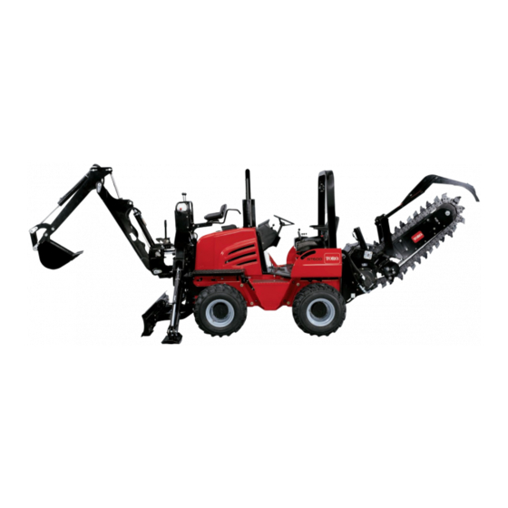
Direct drive trencher
Hide thumbs
Also See for RT600:
- Operator's manual (44 pages) ,
- Installation instructions (4 pages) ,
- Operator's manual (72 pages)

Related Manuals for Toro RT600


Summary of Contents for Toro RT600
- Page 1 Form No. 3407-349 Rev A Direct Drive Trencher RT600 Traction Unit Model No. 25200—Serial No. 316000001 and Up Model No. 25200E—Serial No. 316000001 and Up *3407-349* A Register at www.Toro.com. Original Instructions (EN)
-
Page 2: Table Of Contents
Whenever you need service, genuine Toro parts, or additional Safety and Instructional Decals ......... 4 information, contact an Authorized Toro Service Dealer ..................5 or Toro Customer Service and have the model and serial Preparing the Machine ..........5 numbers of your product ready. Figure 1 illustrates the Installing the Trencher Attachment ...... -
Page 3: Safety
Safety WARNING Lightning can cause severe injury or death. Improperly using or maintaining the trencher can result in injury. To reduce the potential for injury, If lightning is seen or thunder is heard in the area, comply with these safety instructions and those in the do not operate the machine;... -
Page 4: Safety And Instructional Decals
Safety and Instructional Decals Safety decals and instructions are easily visible to the operator and are located near any area of potential danger. Replace any decal that is damaged or lost. Figure 3 1. Decal 125-6670 2. Decal 125-6671 125–6670 1. -
Page 5: Preparing The Machine
Preparing the Machine 2. Set the parking brake. 3. Turn the key to the O position. Important: Ensure that the lifting equipment has a lifting capacity of at least 405 kg (893 lb). 4. Remove the key. 1. Park the machine on a level surface. 5. -
Page 6: Installing The Auger
Installing the Auger (5/8 x 2 (5/8 inch) inches) Installing the Restraint-Bar Brackets (M12 x 4-1/4 (5/8 x 2 (M12) (5/8 inch) inches) inches) -
Page 7: Installing The Hydraulic Hoses
Installing the Hydraulic Hoses 42 cm (16-1/2 inches) 97 cm (38 inches) 88 cm (34-1/2 inches) -
Page 8: Installing The Boom
Testing the hoses 1. Start the machine; refer to the traction unit Operator’s Manual. 2. Operate the trencher-chain direction control and the attachment control (located on the right side of the 75 cm (29-1/2 inches) operator seat) in both directions several times to bleed the air from the hydraulic motor and the hydraulic lift cylinder. - Page 9 Installing the Boom Plates Long boom plates Short boom plates (5/8 x 4-1/2 (M12) (M12) Thick bar clamp Thin bar clamp inches) Place thread locking adhesive on 4 bolts (5/8 x 4-1/2 inches) and install them as shown.
- Page 10 Installing the Wear Pad Channel 10x (short boom) 14x (long boom) (M10) Apply thread-locking adhesive to the bolts (M10) and secure the wear-pad channel onto the boom. Short boom shown...
- Page 11 Installing the Boom-Roller Assembly (3/4 x 1-1/2 inches) 1. Add grease to the washers and ensure that the washers are flush with the roller surface when installing. 2. Install the boom pin through the boom-roller assembly being careful to center the cone spacers before sliding the pin through.
-
Page 12: Installing The Digging Chain
Installing the Wear Pads and Restraint Bar 5x (short boom) 6x (long boom) Wear pad (short and (M10) long shown) Apply thread-locking adhesive to the bolts (M10) and secure the wear pad onto the boom assembly. Short boom shown Torquing the Hardware Bolts (M10) Bolts (M12) Installing the Digging Chain... -
Page 13: Operation
Using the correct trencher components helps to increase Figure 21 the trenching speed and extending the life of the trencher. Contact an Authorized Toro Service Dealer for more 1. H-plate chain information on parts for your trencher. Selecting the Proper Chain Selecting the Proper Digging Teeth It is important to have the correct chain for the job. - Page 14 The arrangement of digging teeth involves both where and how each tooth is attached to the digging chain. Use the following guidelines when you select the arrangements of teeth: • Install teeth that are the same width and are spaced equally around the chain.
-
Page 15: Using The Trencher
Using the Trencher Positioning the Boom for Trenching For the best trenching performance and the smoothest Checking the Tooth-mounting Bolts machine operation, the boom must be in the full down trenching position (Figure 26). Having the boom in this Service Interval: Before each use or daily position pulls the machine down for better traction. - Page 16 12. Decrease the digging chain speed and look at the tachometer. Note: If the engine speed increases, push the utility-traction lever forward until the engine speed is the same that in step 11. Repeat this step to obtain the best trenching speed. Note: Some hard soil conditions allow you to dig a trench faster by reducing the chain speed.
-
Page 17: Operating Tips
If you need the finished trench to be cleaner than what is possible with the trencher, you can purchase a crumber from an Authorized Toro Service Dealer. The crumber, which mounts onto the restraint bar, scrapes the trench clean as you dig. -
Page 18: Maintenance
Maintenance Greasing the Trencher Service Interval: Every 50 hours 1. Clean the grease fittings with a rag. 2. Connect the grease gun to the grease fitting for the bearing of the lower lift cylinder, and apply 3 pumps of grease to the fittings (Figure Figure 29, and... - Page 19 6. Measure the distance between the chain and the bottom 2. Locate the bleed plug (hex-socket) at the side plate on of the lower wear strip (Figure 31). the right side of the boom (Figure 33). • If the gap between the lower wear strip and the chain is 51 to 76 mm (2 to 3 inch), the chain tension is correct (Figure...
- Page 20 Increasing the Chain Tension 2. Clean the area around the dust cap with a cleaning solvent (Figure 34). WARNING 3. Use a needle-nose pliers to rotate the dust cap counterclockwise and remove the cap from the grease If you remove the grease fitting from the boom fitting (Figure 34).
- Page 21 Torquing the Fasteners on the Chain Checking the Trencher Chain Wear Drive Sprocket Strip and Wear Channel Service Interval: After the first 10 hours Service Interval: Before each use or daily After the first 25 hours 1. Lift the chain at the wear strip at the top of the boom, and check the wear strip for signs of damage or Torque the 8 studs and nuts that secure the sprocket for the excessive wear...
- Page 22 Replacing the Trencher Chain Wear 4. Remove the wear strip (Figure 39). Strip 5. Clean the threads of the bolts. 1. Loosen the trencher chain; refer to Decreasing the 6. Apply medium-grade (service removable) Chain Tension (page 19). thread-locking compound to the threads of the bolts. 2.
-
Page 23: Replacing The Digging Chain
Replacing the Digging Chain Removing the Digging Chain Preparing to Remove the Digging Chain 1. Start the machine and move the boom to the full up position. 2. Rotate the digging chain until the master pin is positioned at the top of the idler wheel of the boom (Figure 42). - Page 24 5. When the digging chain has cleared the drive sprocket, Aligning the Digging Chain move the trencher drive control to the N EUTRAL This procedure requires 2 people to align the digging chain to position, turn the machine off, and remove the key the machine.
-
Page 25: Storage
Storage 1. Before storing the machine, brush off the dirt from the attachment. 2. Check the condition of the digging chain. Adjust and lubricate the chain. Replace any worn or damaged parts. 3. Check and tighten all bolts, nuts, and screws. Repair or replace any part that is damaged or worn. -
Page 26: Troubleshooting
Troubleshooting Problem Possible Cause Corrective Action The chain does not turn. 1. A hydraulic fitting is not completely 1. Check and tighten all fittings. connected. 2. A hydraulic fitting is damaged. 2. Replace the damaged fitting. 3. There is an obstruction in a hydraulic 3. - Page 27 Notes:...
- Page 28 If for any reason you are dissatisfied with your Underground Dealer’s service or have difficulty obtaining guarantee information, contact the Toro importer. Australian Consumer Law: Australian customers will find details relating to the Australian Consumer Law either inside the box or at your local Toro Dealer.