Siemens Sinumerik 808D ADVANCED Training Manual
Programming and operating procedures for turning
Hide thumbs
Also See for Sinumerik 808D ADVANCED:
- Diagnostic manual (566 pages) ,
- Parameter manual (524 pages) ,
- Commissioning manual (508 pages)

Related Manuals for Siemens Sinumerik 808D ADVANCED


Summary of Contents for Siemens Sinumerik 808D ADVANCED
- Page 1 Training manual Sinumerik 808D ADVANCED Programming and Operating Procedures for Turning Version 2013-09...
- Page 2 Notes Programming and Operating — Turning Page 2 808D ADVANCED...
-
Page 3: Table Of Contents
Basic knowledge of programming for turning is required, before operating of a machine ! Contents Switch On and Tool Setup Preparation Referencing Create Part Pages 5~7 Pages 13~22 Pages 9~10 Program Part 1 Pages 25~32 Create Part Program Part 2 Pages 35~49 Test Machine... - Page 4 Notes Absolute value and incremental value Manual tool change Editing part program Executing function M Moving axis with handwheel Calculator Part programming Time change Protection levels Creating and measuring tools Program execution Creating zero offsets Breakpoint search Cycles Reference point Dry run RS232c, USB, and network Jogging spindle...
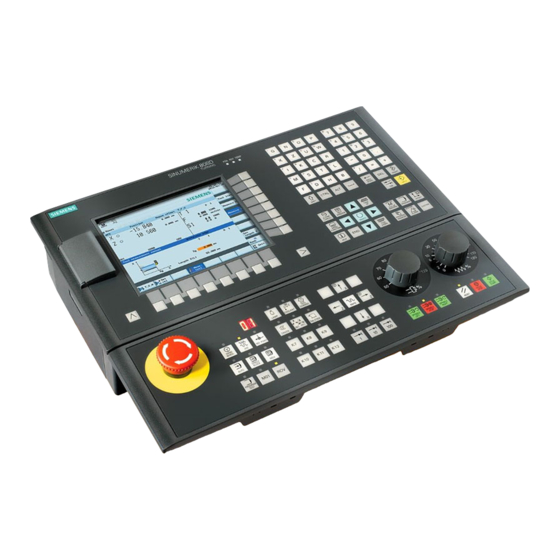
- Page 5 Preparation Unit Description Function of keyboard This unit describes the 808D ADVANCED PPU and MCP functionality, the coordinate system of a turning machine and how to enter passwords to The 808D ADVANCED access the system. panel processing unit (PPU) is used to input data to the CNC and to navigate to operating Unit Content...
- Page 6 Preparation User Moving axis interface Axis movement The 808D machine control panel (MCP) is used to control manual operation of the axis. The machine can be moved 808D ADVANCED with the appropriate keys. (PPU) has eight vertical softkeys (abbr. SK) on the right of the screen.
- Page 7 Preparation SEQUENCE Passwords at the control are used to set the user’s Machine right to access the system. Tasks such as ”Basic Op- Passwords coordinate erating”, “Advanced Operating” and commissioning system functions all depend on the passwords. The Sinumerik 808D ADVANCED uses a No password Machine operator...
- Page 8 Notes Programming and Operating — Turning Page 8 808D ADVANCED...
- Page 9 Switch On Referencing Content Unit Description Switch on This unit describes how to switch the machine on and reference it. machine Please note the explicit switching on rules as specified by the machine manufacturer. Unit Content Step 1 Turn on the main switch of the machine. Switch on The main switch is usually at the rear of the machine.
- Page 10 Switch On Referencing SEQUENCE If your machine is configured with ABS After completing the referencing Reference encoder, you do not need to reference procedure for all axes, the referenced machine the axis of the machine. symbol is displayed next to the axis If your machine is fitted with INC identifier.
- Page 11 Notes 808D ADVANCED Page 11 Programming and Operating — Turning...
- Page 12 Notes Programming and Operating — Turning Page 12 808D ADVANCED...
- Page 13 Tool Setup Content Unit Description A tool must have been created and measured before executing the Create tool This unit describes how to create and set up tools. program. Please make sure the system is in JOG mode. Step 1 Press “Offset”...
- Page 14 Tool Setup SEQUENCE The range of tool numbers which can be created by Principle of correct tool edge position Tool edge Step 2 this system is 1 ~32000. The machine can be loaded position code selection: Select the correspond- with a maximum of 64 tools / 128 tool edges. code ing tool edge position code according to actual tool point direction!
- Page 15 Tool Setup SEQUENCE Example Common tool edge position code choices are as follows: A tool must have been created and Create selected with the cursor before creating tool edge a tool edge. Use “D” code to represent the tool edge. The system activates the Step 1 No.1 tool edge as default at the beginning.
- Page 16 Tool Setup SEQUENCE Step 2 A tool must have been created in the Load tool system before it can be loaded into into active A new tool edge can be added in this way and different lengths and radii position the active position.
- Page 17 Tool Setup SEQUENCE Move Select the required override increment machine Make sure there is no obstruction according to the buttons on the right(this with hand- when moving the tool to avoid a crash. selection fits all axes) wheel The handwheel increment is “0.001 mm” A handwheel can control the axis motion instead of the “JOG”...
- Page 18 Tool Setup SEQUENCE A tool must have been loaded and the Start turret rotated to position. spindle Start the spindle before adjusting tools as follows: Press the “Machine” key on the PPU. Press the “JOG” key on the MCP. Press “Reset” on the MCP to stop the spindle rotation.
- Page 19 Tool Setup SEQUENCE Enter 50 in “ø” Use the traversing keys on the (this is the diameter of the workpiece) MCP to move the axis to the adjusted position. Note: “X=0” or “Z=0” in the workpiece coordinate system is shown as “X0” / “Z0” in the following text.
- Page 20 Tool Setup SEQUENCE Enter “0” in “Z0” Step 2 Set length:Z (this is the distance between the tool point Press the “Set length Z” SK on the and the zero point) PPU. Use the traversing keys on the MCP to move the axis to the ad- justed position.
- Page 21 Tool Setup SEQUENCE Please make sure all the machine A tool must have been loaded and the Execute M axes are in safe positions before spindle function turret rotated to the position! executing the M function! Press the “Machine” key on the PPU. Press the “Machine”...
- Page 22 Tool Setup SEQUENCE The tool setup and workpiece setup Test tool must have been performed correctly so offset results that it can be tested as follows! In order to ensure the machine safety and correctness, the results of the tool offset should be tested appropriately. Press the “Machine”...
- Page 23 Notes 808D ADVANCED Page 23 Programming and Operating — Turning...
- Page 24 Notes Programming and Operating — Turning Page 24 808D ADVANCED...
- Page 25 Program recommended in order to provide clarity for the structure machine operator. Siemens recommends the This unit describes how to create and edit a part program, and get to know following structure: the most important CNC commands required to produce a workpiece.
- Page 26 Create Part Program Part 1 BASIC THEORY Step 4 Create The following sequence should be followed to create You can program a part program: choose “New” or “New direc- Step 1 tory”. Programs can be Choose created with the “New” to “program manager”.
- Page 27 Create Part Program Part 1 BASIC THEORY Edit Inches program and mm Return to change tool N5 G17 G90 G54 The program shown in the editor can be With G71 at the created and edited with the correct keys. header, the N10 T1 D1 T,F,S function geometry data...
- Page 28 Create Part Program Part 1 BASIC THEORY N5 G17 G54 G71 Definition of Absolute positioning; target with G90 at the position N10 T1 D1 beginning of the N15 S5000 M3 G95 F0.3 program, the geometry G500 N20 G00 X100 Z5 N5 G17 G90 G500 data which follows will...
- Page 29 Create Part Program Part 1 BASIC THEORY N5 G17 G90 G54 G71 Feedrate Rapid motion Spindle speed T1 D1 S5000 M3 G95 F0.3 Feed type N20 G00 X50 Z5 Spindle direction N25 G01 Z-5 N5 G17 G90 G54 G71 N30 Z5 When G00 is N35 G00 Z500 Z200...
- Page 30 Create Part Program Part 1 BASIC THEORY Behavior at corners Activation/ deactivation of the tool radius compensa- tion when working on the part contour. G41 / G42 With G41/G42, the radius compensa- tion of the tool will be done in the direction of travel.
- Page 31 Create Part Program Part 1 BASIC THEORY Turning circles and arcs Determine tool radius of T1 D1 The circle radius Tool motion direction N5 G17 G90 G500 shown in the X75, Z-35 ample on the right N10 T1 D1 can be produced N15 S5000 M3 G95 F0.3 Z-130 with the specified...
- Page 32 Create Part Program Part 1 BASIC THEORY Moving to a Controlling fixed the spindle position N5 G17 G90 G500 G71 Using the code G74, N5 G17 G90 G500 G71 The following functions can be the machine can used to influence the operation of N10 T1 D1 N10 T1 D1 move to the...
- Page 33 Notes 808D ADVANCED Page 33 Programming and Operating — Turning...
- Page 34 Notes Programming and Operating — Turning Page 34 808D ADVANCED...
- Page 35 Create Part Program Part 2 Content BASIC THEORY Unit Description Contour turning cycle This unit describes how to create and edit a part program, and get to know the most important CNC commands required to produce a workpiece. Step 1 Part 2 The easiest way to perform roughing/...
- Page 36 Create Part Program Part 2 BASIC THEORY By selecting the “New file” SK, the contour turning data can be After opening the contour data setting window, please make the following inserted into Sub Program File (.SPF). You can edit and change it settings: when selected.
- Page 37 Create Part Program Part 2 BASIC THEORY After completing the steps, the system will return to the Edit interface, press “Tech interface” SK on the PPU to return to the interface for setting the cycle data. After finishing the parameter settings of CYCLE95, press the ”OK”...
- Page 38 Create Part Program Part 2 BASIC THEORY Parameters Meanings Remarks NPP= The first two positions of the name Subprogram name:“DEMO” DEMO:DEMO_E must be letters. (:“DEMO_E ” is created automati- cally) MID=2.5 Maximal feed depth 2.5 mm FALZ=0.2 Finishing allowance at the vertical axis is 0.2 mm FALX=0.1 Finishing allowance at the horizontal...
- Page 39 Create Part Program Part 2 BASIC THEORY Grooving With the “OK” SK, the setting is activated and the The easiest way to selected cycle and data will be transferred to the part produce a groove program automatically as shown below. is to use The machine will cut a groove at the position specified in CYCLE93...
- Page 40 Create Part Program Part 2 BASIC THEORY Parameters Meanings Remarks SPD=30 Starting coordinate at horizontal axis is 30 SPL=-30.5 Starting coordinate at vertical axis is -30.5 WIDG=7 Groove width is 7 mm DIAG=5 Groove depth is 5 mm STA1=0 Angle between contour and vertical axis is 0º (range 0º~180º)...
- Page 41 Create Part Program Part 2 BASIC THEORY Thread cutting With the “OK” SK, the setting is activated and the selected cycle and data will be transferred to the part The easiest way to program automatically as shown below. cut a thread is to The machine will cut a thread at the position use CYCLE99 specified in the cycle.
- Page 42 Create Part Program Part 2 BASIC THEORY Parameters Meanings Remarks SPL=0 Thread start point coordinate at vertical axis is 0 FPL=-18 Thread end point coordinate at vertical axis is -18 mm DH1=20 Thread diameter at start point is 20 DH2=20 Thread diameter at end point is 20 APP=2 Reverse distance is 2 mm...
- Page 43 Create Part Program Part 2 BASIC THEORY With the “OK” SK, the setting is activated and the se- Drilling lected cycle and data will be transferred to the part center holes program automatically as shown below. If there is no other operation, the machine will drill holes The easiest way to at the current position.
- Page 44 Create Part Program Part 2 BASIC THEORY Drilling holes With the “OK” SK, the setting is activated and the The easiest method selected cycle and data will be transferred to the part to drill holes is with program automatically as shown below. CYCLE81/82: With- If there is no other operation, the machine will drill holes out/with dwell at...
- Page 45 Create Part Program Part 2 BASIC THEORY Tapping With the “OK” SK, the setting is activated and the selected cycle and data will be transferred to the part The easiest way to program automatically as shown below. tap a hole is to use If there is no other operation, the machine will drill CYCLE84: Solid holes at the current position.
- Page 46 Create Part Program Part 2 BASIC THEORY Parameters Meanings Remarks DTB=0.5 Pause 0.5 s during final tapping to thread depth (discontinuous cutting) SDAC=3 Spindle state after cycle is M3 Enter values 4/5→M4/ MPIT=12 Thread distance is same as values Negative value→rotate corresponding to the thread size M12 thread left (value range:M3~M48)...
- Page 47 Create Part Program Part 2 BASIC THEORY Cutting off With the “OK” SK, the setting is activated and the selected cycle and data will be transferred to the part The easiest way to program automatically as shown below. cut off a part is to The machine will cut off a part at the position specified use CYCLE92.
- Page 48 Create Part Program Part 2 BASIC THEORY Parameters Meanings Remarks DING1 The speed is reduced at depth of 6 mm DING2 When cutting off the final depth is –1 mm Width of reverse angle is 0.5 mm Or can be set as the radii of reverse circle Fixed cutting speed is 200 mm/min Maximal spindle speed during fixed cutting...
- Page 49 Notes 808D ADVANCED Page 49 Programming and Operating — Turning...
- Page 50 Notes Programming and Operating — Turning Page 50 808D ADVANCED...
- Page 51 Simulate Program Content Unit Description Simulate A part program must have been program created before it can be tested using (axis do not This unit describes how to simulate a part program before executing it in “Simulation”. move) AUTO mode. Step 1 The part program must be opened using the “Program Manager”.
- Page 52 Simulate Program SEQUENCE Step 2 第3步 Step 3 Press the “CYCLE START” key on the MCP. Press the “Simu.” SK on the PPU. If the control is not in the correct mode, a message will be displayed at the bottom of the screen. If this message is displayed at the bottom of the screen, press the “AUTO”...
- Page 53 Notes 808D ADVANCED Page 53 Programming and Operating — Turning...
- Page 54 Notes Programming and Operating — Turning Page 54 808D ADVANCED...
- Page 55 Test Program SEQUENCE Content Before the part program can be loaded Unit Description Program and executed in AUTO mode, it must be Execution tested using the simulation function in This unit describes how to load the program in “AUTO“ mode and test the “Edit”.
- Page 56 Test Program SEQUENCE Before executing the “Dry Run”, please Press the “Machine” key on the PPU. change the offset value appropriately for the Dry Run real workpiece size in order to avoid cutting Press the “Prog. cont.” SK on the PPU. the real workpiece during the dry run and avoid unnecessary danger! Press the “Dry run feedrate”...
- Page 57 Notes 808D ADVANCED Page 57 Programming and Operating — Turning...
- Page 58 Notes Programming and Operating — Turning Page 58 808D ADVANCED...
- Page 59 Machine Pieces SEQUENCE Content Unit Description Make sure the machine has been Time referenced before machining work- Counter This unit describes how to use the “Time, counter” function and how to pieces! machine pieces and the compensation setting for the tool wear. Step 1 Unit Content Press the “Machine”...
- Page 60 Machine Pieces SEQUENCE Make sure the program is correct be- “Cycle time” shows how long the Machine fore machining pieces! Pieces program has been running. Set the program “Remaining time” shows how much time in the ready-to- remains before the program ends. start status as shown on the left in accor-...
- Page 61 Machine Pieces SEQUENCE Step 2 The tool wear compensation must Tool Set the tool length wear parameter of axis X in ”Length X”, the sign distinguish the direction of Wear determines the direction of wear compensation. compensation clearly! Set the tool length wear parameter of axis Z in ”Length Z”, the sign determines the direction of wear compensation.
- Page 62 Notes Programming and Operating — Turning Page 62 808D ADVANCED...
- Page 63 Program Restart SEQUENCE Content Unit Description Block search This unit describes how to restart the part program after a tool has been changed due to damage, or re-machining has to be performed. Press the “Machine” key on the PPU. Press the “Auto” key on the MCP. Unit Content Press the “Block search”...
- Page 64 Program Restart SEQUENCE Press the “CYCLE START” key on the MCP to execute the program. Turn the feed rate override on the MCP gradually to the required value. The feedrate override must always be set to 0%! Make sure the correct tool is selected before continuing! Press the “CYCLE START”...
- Page 65 Notes 808D ADVANCED Page 65 Programming and Operating — Turning...
- Page 66 Notes Programming and Operating — Turning Page 66 808D ADVANCED...
- Page 67 It is recommended to use the “Sinucom PCIN” communication SW Step 1 provided by Siemens to transfer the standard program. Adjust the parameter settings on the PPU to match the settings of the communication SW on PC. Unit Content Press “Program Manager”...
- Page 68 Additional Information Part 1 SEQUENCE Transfer a part program to a PC from the PPU. You can continue sending the part program. Step 2 Press the “OK” SK on the PPU. Press the “NC” SK on the PPU. Use “Cursor + Select” to select the required part Or you can abort the sending of the part program.
- Page 69 Additional Information Part 1 SEQUENCE “USB” is used to transfer the programs to and from the NC. Use the “Copy” “Paste” SKs to transfer the part program from Step 4 NC to USB. Connect a USB device with sufficient memory to the USB interface on the PPU.
- Page 70 Additional Information Part 1 SEQUENCE A shared network drive can be made using an ethernet In the "local configuration Shared Network connection between the PC and the PPU so the data" enter the relevant transferring and backup of NC programs can be parameters.
- Page 71 Additional Information Part 1 SEQUENCE Set the PC's static IP address. On PC create a shared folder. Step 2 Step 3 Anywhere on your PC create a new folder with a simple name (do not use special characters). This example creates a folder named “Test”. Once Ensure PC/PG is connected using a created, right-click the folder and select “Properties.”...
- Page 72 Additional Information Part 1 SEQUENCE In the “Network Drive If the connection is lost Configuration” enter PC select the drive path login user name, and press “Connect.” password, and path of where shared folder is. In accordance to the format required. This will re-establish the connection with PC/PG.
- Page 73 Start” button for machining operation. Press the “TOC” SK on the PPU. The online help from the Siemens manual will be shown. Note: You can also use the “Copy”, “Paste” key to achieve “NC”, “USB” and “Network Drive” moving files. 808D ADVANCED Page 73 Programming and Operating —...
- Page 74 Additional Information Part 1 SEQUENCE The following program shows the interaction of the part program and the R variables screen. parameters Press the “Offset” key on the PPU. Press the “R var.” SK on the PPU. The arithmetic parameters are used in a part program for value assignment, and also for some necessary value calculations.
- Page 75 Additional Information Part 1 SEQUENCE You can change the time on the control if required Press the “OK” SK on the PPU to up date Time when the clocks changes from summer time to winter change time. Press “Shift” and “Alarm” on the PPU simultaneously. Make sure the password is set to the “CUSTOMER”...
- Page 76 Additional Information Part 1 SEQUENCE Gear stages M40, M41, M42, M43, M44 and M45 are available. Press the “OK” SK on the PPU. Automatic gear selection Gear stage 1 Gear stage 2 Gear stage 3 Gear stage 4 Gear stage 5 Example: The machine tool manufacturer specifies a speed range for each gear stage:...
- Page 77 Notes 808D ADVANCED Page 77 Programming and Operating — Turning...
- Page 78 Notes Programming and Operating — Turning Page 78 808D ADVANCED...
-
Page 79: Calculator
Additional Information Part 2 SEQUENCE Content Unit Description Manual A tool must be loaded and rotated to This unit describes how to perform simple tasks on the machine and pro- start the position. vides some additional information which may be required to operate the spindle machine correctly. - Page 80 Workpiece Setup SEQUENCE A tool must have be created and Create measured before it can be used to set workpiece offset the workpiece offset. Make sure the active tool is the measured tool! Press the “Machine” key on the PPU. Press the “JOG”...
- Page 81 Workpiece Setup SEQUENCE Step 2 Press the “Handwheel” key on the MCP to move the tool to the Z0 position on the Using a tool that has a measured “Tool length”, move the tool to a known workpiece. position on the workpiece. Using either JOG or Handwheel, scratch an edge and then calculate the zero point of the workpiece.
- Page 82 Workpiece Setup SEQUENCE The tool setup and workpiece setup In MDA mode, you can enter and execute single and Test tool must have been performed correctly so offset multiple lines of NC codes. results that it can be tested as follows! Use MDA to move the axis to a fixed position.
- Page 83 Additional Information Part 2 SEQUENCE Function program The M function initiates switching operations, such as "Coolant ON/OFF". Frequently used machining sequences, e.g. certain contour shapes, are Various M functions have already been assigned a fixed functionality by stored in subprograms. These subprograms are called at the appropriate the CNC manufacturer.
-
Page 84: Help
Additional Information Part 2 SEQUENCE Sequence Main program Polar coordinates Main program 123 In addition to the common specification in Cartesian coordinates (X, Z), the points of a workpiece can also be specified using polar coordinates. Polar coordinates are also helpful if a workpiece or a part of it is dimen- sioned from a central point (pole) with specification of the radius and the Subprogram N20 L10;... -
Page 85: Part Programming
Additional Information Part 2 SEQUENCE Pole specification relative to the setpoint position last programmed G110 Additive (in the plane, e.g. with G18: Z/X) workpiece offsets (when using G110, please always take the current position of the tool as the reference point to specify the new pole) Pole specification relative to the origin of the current workpiece G111 The programmable workpiece offsets TRANS and ATRANS can be used... - Page 86 Additional Information Part 2 SEQUENCE Program Scaling jump A scale factor can be programmed for all axes with SCALE, ASCALE. The NC programs process their blocks in the sequence in which they were path is enlarged or reduced by this factor in the specified axis. The cur- arranged when they were written.
-
Page 87: Program Execution
Additional Information Part 2 SEQUENCE Program execution Program skip N10 G0 X...Z... Method 1 N5 G90 G500 G71 N40 GOTOF LABEL0; jumps to label LABEL0 “;” code N10 T1 D1 M6 Using “;” code at the … N15 S3000 M3 G94 F300 beginning of the block N20 G00 X50 Z5 can skip this string. - Page 88 Additional Information Part 2 SEQUENCE Method 2 Calculator Press the “Machine” key on the PPU. Press the “Auto” key on the MCP. You can use the calculator to calculate contour elements, values in the program editor, tool offsets and workpiece offsets and enter the results on Press the “Prog cont.”...
- Page 89 Additional Information Part 2 SEQUENCE Press this SK to delete the contents in the calculator. Press this SK to exit the calculator screen. Use this SK to accept the input and write the values to the required position. If the input field is already occupied by a value, the calculator will take this value into the input line.
- Page 90 Notes Programming and Operating — Turning Page 90 808D ADVANCED...
- Page 91 Sample Programs Content DRAWING Unit Description Make make sure all the preparations and Turning safety measures have been performed program 1 This unit shows three typical program examples of frequently used turning before machining! cycles and the corresponding machining diagrams with detailed explana- tions.
- Page 92 Sample Programs Machining Process spindle feedrate in mm/r SUB_PART_1.SPF G00 G90 G95 G40 G71 set spindle upper limit 4500 r/min LIMS=4500 G18 G90 T1 D1 ; ========Start face turning======= G0 X16 Z0 ; =======Start face turning======== constant cutting speed 250 m/min G1 X20 Z-2 G96 S250 M03 M08 Z-20...
- Page 93 Sample Programs DRAWING Machining Process Make sure all the preparations and safety spindle feedrate in mm/r G54 G00 G90 G95 G40 G71 Turning set spindle upper limit 4500 r/min LIMS=4500 measures have been performed before program 2 T1 D1 machining! constant cutting speed 250 m/min G96 S250 M03 M08 ;...
- Page 94 Sample Programs Machining Process ***CONTOUR**** PART_SUB_2.SPF G18 G90 G0 X27 Z0 G1 X24.11 Z-.89 X16 Z-9 Z-21 M2;/* end of contour */ Programming and Operating — Turning Page 94 808D ADVANCED...
- Page 95 Sample Programs DRAWING Machining Process spindle feedrate in mm/r G00 G90 G95 G40 G71 Part of the cycles in the program are Turning set spindle upper limit 4500 r/min LIMS=4500 taken as examples in Section 5, “Create ; ==Start contour turning roughing== program 3 Part Program Part 2”! ;...
- Page 96 Sample Programs Machining Process ; =======Start thread cutting====== ; ============Cutting off========== ; ===========THREAD=========== ; ===========CUT OFF=========== N260 N320 N320 T5 D1 ;CUT-OFF N260 T4 D1 ; THREAD N270 G95→spindle feedrate in mm/r N330 N330 G18 G96 S200 M03 M08 N270 G95 S150 M03 M08 N280 N340...
- Page 97 Sample Programs Machining Process Make sure all the preparations and safety G0X100Z200 Turning T1 D1 measures have been performed before program machining! M3S1000 Rough cycle, cutting depth CYCLE95( "PART_SUB_4", 1.5mm, finish allowance 0.1mm, rough 1.00000, , , 0.10000, 0.12000, 0.12000, cutting feed rate 0.12mm/rev undercut ,1, , , ) federate 0.12 cutting in the longitudinal...
- Page 98 Sample Programs Machining Process PART_SUB_4.SPF Sub program N200 N200 G0X100Z200 N210 Feedrate in mm/min 400 N210 T1 F400 G94 G18 G90 DIAMON N220 Rotational positioning 0 deg N220 G0 X50 Z60 SPOS=0 G0 Z0 X-.5 N230 Set the second spindle as main N230 SETMS(2) G1 X20...
- Page 99 Notes 808D ADVANCED Page 99 Programming and Operating — Turning...
- Page 100 Notes Programming and Operating — Turning Page 100 808D ADVANCED...
- Page 101 ISO Mode BASIC THEORY Content Module Description Siemens standard machining codes are imple- This unit describes the ISO operating functions in 808D ADVANCED, com- mented in DIN mode. The 808D ADVANCED also function pares the similarities and differences of the machining code in DIN mode...
- Page 102 ISO Mode BASIC THEORY After pressing All the ISO codes described in this unit code “OK”, the sys- can be implemented in the ISO mode of explanation tem restarts the 808D ADVANCED system! automatically. Brief description of typical, frequently used ISO codes After restart- ISO code Description...
- Page 103 ISO Mode BASIC THEORY Code M3 S2000; spindle rotation G98:Spindle in mm/min F500 G01 X100; feedrate is 500 circular interpolation CW mm/min G99:Spindle in mm/r Motion path: Start point→end G92 X50 W-20 F2 ;F is the thread point lead G80:Cancel fixed cycle CW (rear tool coordinate sys- G04 X2.0 ;delay 2 s...
- Page 104 ISO Mode BASIC THEORY Frequently used letter meanings of typical fixed cycle codes in ISO mode Brief introduction of typical fixed cycle codes in ISO mode Descriptions Unit Applied range and note For the meaning of letters when programming typical fixed cycles, please refer the figure on the left! Cutting end point X/Z absolute coordinate G90 / G94 / G74...
- Page 105 ISO Mode BASIC THEORY shaft roughing cycle radical roughing cycle Programming structures: Programming structures: G71 U(Δd)—R(e); G72 W(Δd)—R(e); G71 P(ns)—Q(nf)—U(Δu)—W(Δw)—F—S—T G72 P(ns)—Q(nf)—U(Δu)—W(Δw)—F—S—T; N(ns)… N(ns)… … … … … N(nf); N(nf); P(ns) / Q(nf): Indicating start/end point of P(ns) / Q(nf): Indicating start/end point of finishing program block path finishing program block path Note:Please follow the specified structures when programming!...
- Page 106 ISO Mode BASIC THEORY finishing cycle closed cutting cycle Programming structures: Programming structures: G73 U(Δi)—W(Δk)—R(d); G70 P(ns)—Q(nf); P(ns) / Q(nf):Indicating start/end point of finishing program block path G73 P(ns)—Q(nf)—U(Δu)—W(Δw)—F—S—T; N(ns)… Note: T / S / F used in G70 must be specified in G71/G72/G73 fixed cycles be- …...
- Page 107 ISO Mode BASIC THEORY shaft grooving multi-cycles sample program: radical grooving multi-cycles O007; Programming structures: Programming structures: M3 S1500 G74 R(e); G75 R(e); G0 X40 Z5 G74 R0.5 G74 X / U—Z / W—P(Δi)—Q(Δk)—R(Δd) G75 X / U—Z / W—P(Δi)—Q(Δk)—R(Δd)—F; ;...
- Page 108 ISO Mode BASIC THEORY thread cutting cycle sample program: thread cutting multi-cycles Programming structures: O0012; Programming structures: M3 S1500 Straight thread cutting cycle in mm G76 P(m)(r)(a)—Q(Δd )—R(d); G0 X150 Z50 T0101; thread tool G92 X / U—Z / W—F; G0 X65 Z5 G76 X / U—Z / W—R(i)—P(k)—Q(Δd)—F(I);...
-
Page 109: Program
ISO Mode BASIC THEORY Common ISO prog. 808D ISO prog. Beginning of the program The ISO mode function provided by the program Common ISO programs: 808D ADVANCED can easily operate the O0001; O0001;delete transfer and Beginning is “O” existing ISO program! G0 X100 Z100 M5 G0 X100 Z100 M5 operation... -
Page 110: Program
ISO Mode BASIC THEORY F / T / S in G70 808D ISO prog. G90/G94 与 G71 808D ISO prog. ISO mode in 808D ISO mode in 808D N89 G71 U1.5 R1 F0.3 N70 G90 X43 Z-130 ADVANCED: N90 G71 P100 Q170 U0.5 W-0.2; ADVANCED: N80 X41;... -
Page 111: Sample
ISO Mode BASIC THEORY Sample program (target workpiece is the same as in Program execution. Section 5 Step 3 Step 5 “Create Part Program Part 2” Make sure the current system is in ISO mode! Make sure the current system is in ISO mode! Make sure all preparations and safety measures have been Make sure all preparations and safety measures have been performed! -
Page 112: Program
Notes Programming and Operating — Turning Page 112 808D ADVANCED... -
Page 113: Reference Point
Support Circular interpolation through intermediate point Contact Circular interpolation: tangential transition Thread cutting with constant lead Useful G331 Thread interpolation Siemens G332 Thread interpolation — Retraction Websites Group 2: Non-modally valid motion. dwell Name Meaning Dwell time preset Tapping without synchronization... -
Page 114: Program
Appendix Group 3: Programmable frame Group 8: Settable zero offset Name Meaning Name Meaning TRANS Translation G500 * Settable zero offset OFF Rotation 1st settable zero offset 2nd settable zero offset SCALE Programmable scaling factor 3rd settable zero offset MIRROR Programmable mirroring 4th settable zero offset ATRANS... -
Page 115: Program
G710 Metric dimension data input, also feedrate F Group 47: External NC languages modally effective Name Meaning Group 14: Absolute/incremental dimension modally effective G290 * Siemens mode Name Meaning G291 External mode G90 * Absolute dimension data input Incremental dimension data input... -
Page 116: Program
If you have any questions about this product or this manual, please contact the hotline: Phone +86 1064 719990 +86 1064 719991 E-mail 4008104288.cn@siemens.com Siemens Websites SINUMERIK internet address Further product information can be found at the following website: http://www.siemens.com/sinumerik Programming and Operating —... -
Page 117: Program
Notes 808D ADVANCED Page 117 Programming and Operating — Turning... -
Page 118: Pages
Printed in Germany All product designations may be trademarks or product names of © Siemens AG 2012 Siemens AG or supplier companies whose use by third parties for their own purposes could violate the rights of the owners.