Siemens Sinumerik 808D Operating Manual
For milling
Hide thumbs
Also See for Sinumerik 808D:
- Diagnostic manual (566 pages) ,
- Parameter manual (524 pages) ,
- Commissioning manual (508 pages)
Advertisement
Quick Links
Advertisement

Related Manuals for Siemens Sinumerik 808D


Summary of Contents for Siemens Sinumerik 808D
- Page 1 Training manual Sinumerik 808D Programming and Operating Procedures for Milling Version 2013-01...
- Page 2 Notes Operating and Programming — Milling Page 2 808D...
- Page 3 Basic knowledge of programming for milling is required, before operating of a machine ! Contents Switch On and Tool Setup Preparation Referencing Pages 5~7 Pages 13~20 Pages 9~10 Workpiece Setup Pages 23~27 Create Part Program Part 1 Pages 29~36 Test Simulate Machine Program...
- Page 4 Index Absolute incremental dimensioning Manual tool change Editing part program Executing M function Moving axis with handwheel Calculator Part programming Changing time Protection levels Contour editor Program execution Creating and measuring tools Block search Creating zero offsets Reference point Cycles RS232c and USB Dry run Saving data...
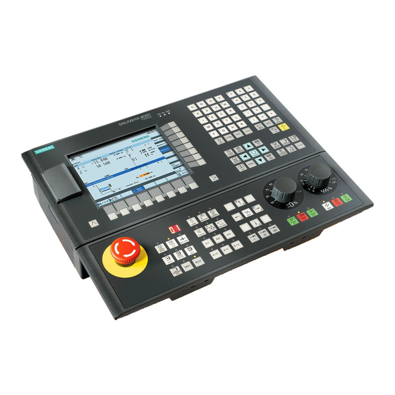
- Page 5 Preparation Content Basic Theory Unit Description Function of This unit describes the 808D PPU and MCP functionality, the coordinate keyboard system of a milling machine and how to enter passwords to access the system. The 808D panel pro- cessing unit (PPU) is used to input data to the CNC and to navi- Unit Content...
- Page 6 Preparation User Moving axis interface Axis remove The 808D machine control panel (MCP) is used to con- trol manual operation of the axis. The machine can be moved with the appropriate keys. 808D (PPU) has eight vertical softkeys (abbr. SKs) on the right of the screen.
- Page 7 Tasks such as ”Basic Op- coordinate Passwords system erating”, “Advanced Operating” and commissioning functions all depend on the passwords. The Sinumerik 808D uses a coordinate system which is No password Machine operator derived from the DIN 66217 Customer’s password Advanced operator standard.
- Page 8 Notes Operating and Programming — Milling Page 8 808D...
- Page 9 Switch On Referencing Content SEQUENCE Unit Description Switch on machine This module describes how to switch the machine on and reference it. Please note the explicit switching on rules as specified by the machine manufacturer. Unit Content Step 1 Turn on the main switch of the machine. Switch on The main switch is usually at the rear of the machine.
- Page 10 Switch On Referencing SEQUENCE Reference After power on, the machine must first After completing the referencing be referenced! machine procedure for all axes, the refer- enced symbol is displayed next to the axis identifier. Step 1 After power on, the machine will be in the reference point approach mode (default).
- Page 11 Notes 808D Page 11 Operating and Programming — Milling...
- Page 12 Notes Operating and Programming — Milling Page 12 808D...
-
Page 13: Unit Description
Tool Setup SEQUENCE Content Unit Description A tool must have been created and Create tool measured before executing the pro- This unit describes how to create and set up tools. gram. Step 1 Please make sure the system is in JOG mode. Press “Offset”... - Page 14 Tool Setup SEQUENCE The range of tool numbers which can be created Step 2 Create tool A tool must have been created and by this system is 1 ~32000. edge selected before creating a tool edge! The machine can be loaded with a maximum of 64 tools / 128 tool edges.
- Page 15 Tool Setup SEQUENCE Step 2 A tool must have been created in the Load tool system before it can be loaded into the A new tool edge can be added in this way and different lengths and radii into Spindle can be entered as required.
- Page 16 Tool Setup SEQUENCE The tool are usually loaded manually into the spindle. Select the required override increment according to the buttons on the right The tool will be automatically loaded into the spindle with an automatic (this selection fits all axes) tool changer.
- Page 17 Tool Setup SEQUENCE A tool must have been loaded and ro- Start tated to the position. spindle Start the spindle before adjusting tools as follows: Press the “Machine” key on the PPU Press “Reset” on the MCP to stop the Press the “T.S.M”...
- Page 18 Tool Setup SEQUENCE Use “SELECT” key to set the refer- ence point as “workpiece” (In real Press the axis keys on the MCP to measurement, the reference point move the tool to the set position can be set as either “workpiece” or above the workpiece.
- Page 19 Tool Setup SEQUENCE Enter “0” at “X0” Enter “0” at “Y0” Press the axis keys on the MCP to (This is the value of the width of a move the tool to the set position. setting block if it is used.Select one of X0/Y0 according to requirement.) Press the “Handwheel”...
- Page 20 Tool Setup SEQUENCE Please make sure all the machine axes Execute M A tool must be loaded to the spindle. are in safe positions before executing Jog spindle function the M function! Press the “Machine” key on the PPU. Press the “Machine” key on the PPU. Press the “JOG”...
- Page 21 Notes 808D Page 21 Operating and Programming — Milling...
- Page 22 Notes Operating and Programming — Milling Page 22 808D...
- Page 23 Workpiece Setup SEQUENCE Content Unit Description Manual A tool must have been loaded into start the spindle. This unit describes how to set the workpiece offset and test the tool re- spindle sults. Before measuring, the spindle can be started as follows: Press the “Machine”...
- Page 24 Workpiece Setup SEQUENCE A tool must have be created and Create workpiece measured before it can be used to set offset the workpiece offset. Make sure the active tool is the measured tool! Press the “Machine” key on the PPU. Press the “JOG”...
- Page 25 Workpiece Setup SEQUENCE Method1 This method is normally for setting the zero point of the work- Press the “Handwheel” piece at the edge of the workpiece. key on the MCP to position the tool at the X0 edge of the work- piece.
- Page 26 Workpiece Setup SEQUENCE Method 2 This method is normally used for setting the workpiece zero Method 3 This method is normally used for setting the zero points at the point at the center point of a rectangular workpiece. center point of a circular workpiece. Using tools with a measured “length and radius”, move them to the four Using tools with a measured “length and radius”, move them to the three edges of the rectangular workpiece.
- Page 27 Workpiece Setup SEQUENCE The tool setup and workpiece setup Test tool must have been performed correctly so offset results that it can be tested as follows! In order to ensure the machine safety and correctness, the results of the tool offset should be tested appropriately. Press the “Machine”...
- Page 28 Notes Operating and Programming — Milling Page 28 808D...
-
Page 29: Basic Theory
Program recommended in order to provide clarity for the structure machine operator. Siemens recommends the This unit describes how to create a part program, edit the part program following structure: and get to know the most important CNC commands required to produce a workpiece. - Page 30 Create Part Program Part 1 SEQUENCE Step 4 The following sequence should be followed to create Create a part program: You can program choose “New” or “New direc- Step 1 tory”. Programs can be created with the Choose “program manager”. “New”...
- Page 31 Create Part Program Part 1 Basic Theory Edit Inches and program Header N5 G17 G90 G54 The program shown in the editor can be With G71 at the created and edited with the appropriate header, the ge- keys. N10 T1 D1 M6 T,F,S function ometry data will N15 S5000 M3 G94 F300...
- Page 32 Create Part Program Part 1 Basic Theory N5 G17 G54 G71 Definition of Absolute positioning; target position with G90 at the header, N10 T1 D1 M6 the geometry data which N15 S5000 M3 G94 F300 follows will be interpret- N5 G17 G90 G500 G500 N20 G00...
- Page 33 Create Part Program Part 1 Basic Theory N5 G17 G90 G54 G71 Feedrate Rapid motion Spindle speed T1 D1 M6 S5000 M3 G94 F300 Feed type N20 G00 X50 Y50 Z5 N25 G01 Z-5 N5 G17 G90 G54 G71 Spindle direction N30 Z5 When G00 is...
- Page 34 Create Part Program Part 1 Basic Theory Contour feedrate with When traversing circular Behavior at contours with cutter radius corners compensation, it should be decided whether the feed rate should be calculated Activation/ along the contour of the deactivation of the workpiece or along the path tool radius compen- defined by the center point...
- Page 35 Create Part Program Part 1 Basic Theory Milling circles and Determine tool radius of T1 D1 arcs Tool motion direction N5 G17 G90 G500 The circle radius shown in the example on the X100, Y50 N10 T1 D1 M6 X0, Y50 right can be produced N15 S5000 M3 G94 F300 with the specified part...
- Page 36 Create Part Program Part 1 Basic Theory Moving to a Controlling fixed the spindle position The following functions can be Using the code G74, N5 G17 G90 G500 G71 N5 G17 G90 G500 G71 used to influence the operation the machine can of the spindle: N10 T1 D1 M6 N10 T1 D1 M6...
- Page 37 Notes 808D Page 37 Operating and Programming — Milling...
- Page 38 Notes Operating and Programming — Milling Page 38 808D...
- Page 39 Create Part Program Part 2 Content Basic Theory Unit Description Radius and chamfers This unit describes how to create a part program, edit the part program and get to know the most important CNC commands required to produce a workpiece. The two radii and the chamfer shown Part 2...
- Page 40 Create Part Program Part 2 Basic Theory With the “OK” SK, the values and Hole cycle call will be transferred to centering the part program as shown be- low. The easiest way to This will drill a hole at the current center drill a hole position.
- Page 41 Create Part Program Part 2 Basic Theory With the “OK” SK, the values and Drilling cycle call will be transferred to the holes part program as shown below. This will drill a hole at the current The easiest method to drill position.
- Page 42 Create Part Program Part 2 Basic Theory DAM parameter For descriptions of RTP, RFP, SDIS and DP, please see page 40 ①DAM≠0, the first drilling operation(FDPR)cannot exceed the drilling depth. As of the second drilling operation, the drilling is acquired from the last depth operation FDEP=5 Reach first drilling hole depth.
- Page 43 Create Part Program Part 2 Basic Theory With the “OK” SK, the values and cycle call will be transferred to the Tapping part program as shown below. This will drill a hole at the current position. The easiest way to If there is no other operation, the ma- tap a hole is to use chine will drill holes in the current...
- Page 44 Create Part Program Part 2 Basic Theory For descriptions of RTP, RFP, SDIS, DP and DTB, please see page 40 For descriptions of AXH, VARI, DAM and VRT, please see page 42 Parameters Meanings Remarks DTB=0.7 Pause 0.7 s during final tapping to thread depth (discontinuous cutting) SDAC=5 Spindle state after cycle is M5...
- Page 45 Create Part Program Part 2 Basic Theory With the “OK” SK, the val- Hole ues and cycle call will be positioning transferred to the part pro- gram as shown below. This will drill holes at the The easiest way to positions defined from drill a series of within the cycle.
- Page 46 Create Part Program Part 2 Basic Theory The contour can be edited and stored in the main program file Contour after the M30 command when using the “Attach contour” SK. milling with cycle Enter the cycle data setting The easiest way to according to the former opera- rough and finish tions in the screen and enter...
- Page 47 Create Part Program Part 2 Basic Theory When you have opened the screen for setting the contour data, you can The selected di- make the following settings: rection is shown at the top left side of PPU. Enter appropriate start point coordi- The meanings of nates as in the the highlighted...
- Page 48 Create Part Program Part 2 Basic Theory After completing the steps, the system will re- For descriptions of RTP, RFP, SDIS and DP, please see page 40 turn to the edit interface. Press “Technical Parameters Meanings Remarks interface” on the PPU to return to the interface for setting the cycle data.
- Page 49 Create Part Program Part 2 Basic Theory With the “OK” SK, the values and cycle call will be trans- Milling slots ferred to the part program as shown below. and spigots This will perform milling at the position defined in the cycle.
- Page 50 Create Part Program Part 2 Basic Theory Parame- Meanings Remarks ters NUM=3 Three slots on the circle AFSL=30 Angle slot length is 30º AFSL and WID jointly decide the shape of the slot in WID=6 Slot width is 6 mm the plane STA1=165 Start angle,angle between the effective work piece...
- Page 51 Notes 808D Page 51 Operating and Programming — Milling...
- Page 52 Notes Operating and Programming — Milling Page 52 808D...
-
Page 53: Module Description
Simulate Program SEQUENCE Content Module Description A part program must have been created Simulate before it can be tested using program This unit describes how to simulate a part program before executing it in “Simulation”. (Axis do not AUTO mode. move) Step 1 The part program must be opened using the “Program Manager”... - Page 54 Simulate Program SEQUENCE Step 2 Step 3 Press the “CYCLE START” key Press the “Simu.” SK on the PPU. on the MCP. If the control is not in the correct mode, a message will be displayed at the bottom of the screen.
- Page 55 Notes 808D Page 55 Operating and Programming — Milling...
- Page 56 Notes Operating and Programming — Milling Page 56 808D...
- Page 57 Test Program Content SEQUENCE Before the part program can be loaded Unit Description Program and executed in AUTO mode, it must be Execution tested using the simulation function This unit describes how to load the program in “AUTO“ mode and test the mentioned previously! part program at fixed speed.
- Page 58 Test Program SEQUENCE Before executing the “Dry Run”, please Press the “Machine” key on the PPU. change the offset value appropriately for Dry Run the real workpiece size in order to avoid Press the “Prog. cont.” SK on the PPU. cutting the real workpiece during the dry run and avoid unnecessary danger! Press the “Dry run feedrate”...
- Page 59 Notes 808D Page 59 Operating and Programming — Milling...
- Page 60 Notes Operating and Programming — Milling Page 60 808D...
- Page 61 Machine Pieces Basic Theory Content Unit Description Make sure the machine has been refer- Time Coun- enced before machining workpieces! This unit describes how to use the Time counter function and how to machine pieces and the compensation setting for the tool wear. Step 1 Unit Content Press the “Machine”...
- Page 62 Machine Pieces SEQUENCE “Cycle time” shows how long the pro- Make sure the program is correct before Machine gram has been running. Pieces machining pieces! Set the program in “Time left” shows how much time re- mains before the program ends. the ready-to-start status as shown on the left in accord-...
- Page 63 Machine Pieces SEQUENCE Step 2 Tool The tool wear compensation must Set the tool length wear parameter of axis X in ”Length X”, the sign deter- Wear distinguish the direction of compensa- mines the direction of wear compensation. tion clearly! Set the tool length wear parameter of axis Z in ”Length Z”, the sign deter- mines the direction of wear compensation.
- Page 64 Notes Operating and Programming — Milling Page 64 808D...
- Page 65 Program Restart Content SEQUENCE Unit Description Block Search This unit describes how to restart the part program after a tool has been changed due to damage, or remachining has to be performed. Press the “Machine” key on the PPU. Press the “Auto” key on the MCP. Unit Content Press the “Block search”...
- Page 66 Program Restart SEQUENCE Press the “Back” SK on the PPU. Press the “CYCLE START” key on the MCP to execute the program. Turn the feedrate override on the MCP gradually to the required value. The feedrate override must always be set to 0%! Make sure the correct tool is selected before continuing! Press the “CYCLE START”...
- Page 67 Notes 808D Page 67 Operating and Programming — Milling...
- Page 68 Notes Operating and Programming — Milling Page 68 808D...
-
Page 69: Additional Information
It is recommended to use the “SINUCOM PCIN” communication Step 1 SW provided by Siemens to transfer the standard program. Adjust the parameter settings on the PPU to match the settings of the Unit Content communication SW on the PC. - Page 70 Additional Information Part 1 SEQUENCE Step 2 Transfer a part program to a PC from the PPU. You can continue sending the part program. Press the “NC” SK on the PPU. Press the “OK” SK on the PPU. Use “Cursor + Select” to select the required part program. Or you can abort the sending of the part program The selected program will be highlighted.
- Page 71 Press the “TOC” SK on the PPU. Use “Cursor + Select” to select the required part program. The selected program will be highlighted. The online help from the Siemens manual will be Press the “Copy” SK on the PPU. shown.
- Page 72 Additional Information Part 1 SEQUENCE Step 2 Manual face Press “Face cutt.” SK on PPU. cutting Enter appropri- ate data in the “Face cutting” is used to cut the oversized materials on the rough face ”Face Milling” before starting to machine. window ac- cording to the Step 1...
- Page 73 Additional Information Part 1 SEQUENCE parameters Press the “Offset” key on the PPU. Press the “R var.” SK on the PPU. The arithmetic parameters are used in a part program for value assign- ment, and also for some necessary value calculations. The required val- ues can be set or calculated by the control system during program execu- N10 G17 G90 G54 tion.
- Page 74 Additional Information Part 1 SEQUENCE You can change the time on the control if required Press the “OK” SK on the PPU. Time when the clocks changes from summer time to winter change time. Press “Shift” and “Alarm” on the PPU simul- taneously.
- Page 75 Additional Information Part 1 SEQUENCE Press the “OK” SK on the PPU. Gear stages M40, M41, M42, M43, M44 and M45 are available. Automatic gear selection Gear stage 1 Gear stage 2 Gear stage 3 Gear stage 4 Gear stage 5 Example: The machine tool manufacturer specifies a speed range for each gear stage:...
- Page 76 Notes Operating and Programming — Milling Page 76 808D...
- Page 77 Additional Information Part 2 SEQUENCE Content In MDA mode, you can enter and execute single Unit Description This unit describes how to perform simple tasks on the machine and and multiple lines of NC codes. provides some additional information which may be required to operate the machine correctly.
- Page 78 Additional Information Part 2 SEQUENCE Subpro- function gram The M function initiates switching operations, such as "Coolant ON/ OFF". Various M functions have already been assigned a fixed function- Frequently used machining sequences, e.g. certain contour shapes, are ality by the CNC manufacturer. The M functions not yet assigned are stored in subprograms.
- Page 79 Additional Information Part 2 SEQUENCE Sequence Polar Main program coordinates MAIN 123 In addition to the common specification in Cartesian coordinates (X, Y, Z), the points of a workpiece can also be specified using polar coordi- nates. Subprogram N20 L10; call Polar coordinates are also helpful if a workpiece or a part of it is dimen- sioned from a central point (pole) with specification of the radius and the angle.
-
Page 80: Basic Theory
Additional Information Part 2 Basic Theory G110 Pole specification relative to the setpoint position last programmed Additive (in the plane, e.g. with G17: X/Y) workpiece (when using G110, please always take the current position of the offsets tool as the reference point to specify the new pole) The programmable workpiece offsets TRANS and ATRANS can be used Pole specification relative to the origin of the current workpiece G111... - Page 81 Additional Information Part 2 Basic Theory Coordinate rotation Scaling ROT AROT A scale factor can be programmed for all axes with SCALE, ASCALE. The The programmable rotation ROT, AROT can be used: path is enlarged or reduced by this factor in the specified axis. The cur- rently set coordinate system is used as the reference for the scale The rotation is performed in the current plane G17, G18 or G19 using the change.
- Page 82 Additional Information Part 2 Basic Theory SUPA→cancel all settable offsets SUPA G00 Z300 D0 Program SUPA G00 X0 Y0 example coordinate plane G17,use tool 1 G17 T1 D1 MSG ("change to 1 tool") M5 M9 M00 S5000 M3 G94 F300 This describes and analyzes the additive offset, coordinate rotation, G00 X-28 Y 30 scaling functions mentioned above.
- Page 83 Additional Information Part 2 Basic Theory Program execution Program jump N10 G0 X...Z... NC programs process their blocks in the sequence in which they were arranged when they were written. The processing sequence can be N40 GOTOF LABEL0; jumps to label LABEL0 changed by introducing program jumps.
- Page 84 Additional Information Part 2 Basic Theory Method 2 Program skip Press the “Machine” key on the PPU. Method 1 Press the “Auto” key on the MCP. N5 G17 G90 G500 G71 Press the “Prog cont.” SK on the PPU. “;” code N10 T1 D1 M6 Using “;”...
- Page 85 Additional Information Part 2 SEQUENCE Basic Theory Press this SK to delete the contents in the calculator. Calculator Press this SK to exit the calculator screen. Use this SK to accept the input and write the values to the required position. You can use the calculator to calculate contour elements, values in the If the input field is already occupied by a value, the calculator program editor, tool offsets and workpiece offsets and enter the results...
- Page 86 Notes Operating and Programming — Milling Page 86 808D...
- Page 87 Sample Program Drawing Content Unit Description Make sure all the preparations and safe- Milling ty measures have been performed be- program 1 This unit shows three typical program examples of frequently used milling fore machining! cycles and the corresponding machining diagrams with detailed explana- tions.
- Page 88 Sample Program Machining Process G17 G90 G54 G60 ROT ; =======Repeat rectangular pocket milling ; ====Repeat ② ③ ④ rectangular pocket tool 1 is plane milling tool T1 D1; FACEMILL 3 times========== milling 3 times===== N200 REPEAT _ANF _END P=3 N200 Repeat N160 ~ N190 operation three times...
- Page 89 Sample Program Drawing Machining Process N290 G0 X0 Y0 N290 back to workpiece zero point Make sure all the preparations and safety Milling ; =====Start circular pocket roughing===== ; =============Start circular pocket measures have been performed before N300 milling circular groove (depth 5 program 2 roughing============== machining!
- Page 90 Sample Program Machining Process G17 G90 G60 G54 ;*************CONTOUR************ This program is additional descrip- tool 1 is milling tool, diameter 50 mm CON1: T1 D1 ;FACEMILL D50 tion information created by the system automatically after finishing ;#7__DlgK contour definition begin - Don't back to workpiece zero point S3500 M3 change!;*GP*;*RO*;*HD*...
- Page 91 Sample Program Drawing Machining Process G17 G90 G54 G71 Part of the cycles in the program are Milling SUPA G00 Z300 D0 taken as examples in Section 5, “Create program 3 SUPA G00 X300 Y300 Part Program Part 2”! T1 D1 hint:change to tool 1 MSG ("Please change to Tool No 1") M05 M09 M00...
- Page 92 Sample Program Machining Process N270 N430 N270 SUPA G00 Z300 D0 N430 SUPA G00 Z300 D0 N440 N280 N280 SUPA G00 X300 Y300 N440 SUPA G00 X300 Y300 ; ======Contour milling start====== N290 N290 T4 D1 ; ======Contour milling start====== N450 N300 hint:change to tool 4...
- Page 93 Sample Program Machining Process N580 N790 N580 SUPA G00 Z300 D0 N790 SUPA G00 Z300 D0 N590 N800 N590 SUPA G00 X300 Y300 N800 SUPA G00 X300 Y300 ; =========Centering start======= ; ==========Tapping start======== ; ========Centering start========= N600 ; =========Tapping start========= N810 N610 hint:change to tool 6...
- Page 94 Sample Program Machining Process N1100 ;*************CONTOUR************ This section is additional description N1110 CONT1: information created by system automati- N1120 ;#7__DlgK contour definition begin - cally after finishing the programming of Don't change!;*GP*;*RO*;*HD* the rough cutting CYCLE95 and does N1130 G17 G90 DIAMOF;*GP* not affect the system execution.
- Page 95 Notes 808D Page 95 Operating and Programming — Milling...
- Page 96 Notes Operating and Programming — Milling Page 96 808D...
-
Page 97: Unit Description
Mode Basic Theory Content Unit Description Siemens standard machining codes are implemented in DIN mode. The 808D also provides also provides appro- function switch This unit describes the ISO operating functions in 808D, compares the priate functions for implementing the ISO commands, similarities and differences of the machining code in DIN mode and ISO but the ISO mode must be activated during operation. - Page 98 Mode Basic Theory After pressing All the ISO codes described in this unit “OK”, the sys- code can be implemented in the ISO mode of tem restarts auto- explanation the 808D system! matically. After restarting, Brief description of typical, frequently used ISO codes press “Shift”...
- Page 99 Mode Basic Theory Code In DIN mode, the tool length H01→Offset value 20.0 is activated automatically, H02→Offset value -30.0 but in ISO mode, you must circular interpolation in H03→Offset value 30.0 activate the tool length via positive direction H04→Offset value -20.0 G code.
- Page 100 Mode Basic Theory Frequently used letter meanings of typical fixed cycle codes in ISO Brief introduction of typical fixed cycle codes in ISO mode For the meaning of letters when programming typical fixed Descriptions Applied range and Unit note cycles, please refer the figure on the left! Cutting end point X/Z absolute coordi- G73 / G74 / G76 nate values...
- Page 101 Mode Basic Theory Boring cycle application example program: application example program: Drilling cycle (countersink drilling) Common programming structures: Common programming structures: M3 S500 ;spindle rotation M3 S2000 ;spindle rotation G76 X—Y—Z—R—Q—P—F—K G82 X—Y—Z—R—P—F—K G90 G99 G90 G99 G82 X300 Y-250 Z-150 R-100 P1000 F120 Motion process:...
- Page 102 Mode Basic Theory Tapping cycle execution operation graphic: boring cycle execution operation graphic: With command G99 without operation in red line With command G99 without operation in red line Common programming structures: Common programming structures: With command G98 with operation in red line With command G98 with operation in red line G84 X—Y—Z—R—P—F—K G86 X—Y—Z—R—F—K...
- Page 103 Mode Basic Theory execution operation The ISO mode function provided by Boring cycleⅠ / reverse boring cycle graphic: program the 808D can easily operate the exist- Ⅱ transfer and Common programming structures: ing ISO program! Fixed cycle Ⅱ→ operation spindle start G87 X—Y—Z—R—Q—P—F—L Motion process:...
- Page 104 Mode Basic Theory Common ISO program 808D ISO program Program execution Beginning of the program Step 3 O0001; O0001;Delete this Common ISO program: G0 X50 Y50 Z50 M5 line Beginning is “O” Make sure the current system is in ISO mode! G04 X5 G0 X50 Y50 Z50 M5 ISO mode of 808D:...
- Page 105 Mode Basic Theory ISO programs can be executed in the 808D as follows: Step 5 Sample program Make sure the current system is in ISO mode! G291 N210 T2M6 Make sure all preparations and safety measures have been T1M6 N220 M3S3000F100 performed! G0G54G90G40 N230 G43H2Z50...
- Page 106 Mode Basic Theory N160 G0G40G90Z60 Standard Siemens programming. Machining the same workpiece as N170 M09M05 N180 M30 described above (can be compared The next paragraph describes with the ISO code). the codes of the contour. The system will generate them auto- N10 T1D1M6 ;...
- Page 107 Notes 808D Page 107 Operating and Programming — Milling...
- Page 108 Notes Operating and Programming — Milling Page 108...
- Page 109 Circular interpolation; tangential transition Contact Thread cutting with constant lead G331 Thread interpolation Useful G332 Thread interpolation - retraction Siemens Websites Group 2: Non-modally valid motion, dwell Name Meaning Dwell time preset Tapping without synchronization Reference point approach with synchronization...
- Page 110 Appendix Group 3: Programmable frame Group 8: Settable zero offset Name Meaning Name Meaning TRANS Translation G500 * Settable work offset OFF Rotation 1st settable zero offset SCALE Programmable scaling factor 2nd settable zero offset MIRROR Programmable mirroring 3rd settable zero offset ATRANS Additive translation 4th settable zero offset...
- Page 111 G710 Metric dimension data input; also for feedrate F Group 47: External NC languages modally effective Name Meaning Group 14: Absolute/incremental dimension modally effective G290 * Siemens mode Name Meaning G291 External mode G90 * Absolute dimensions data input Incremental dimension data input...
-
Page 112: Technical Support
If you have any questions about this product or this manual, contact the hotline: Phone +86 1064 719990 +86 1064 719991 E-mail 4008104288.cn@siemens.com Useful Siemens Websites SINUMERIK Internet address Further product information can be found at the following web site: http://www.siemens.com/sinumerik... - Page 113 Notes 808D Page 113 Operating and Programming — Milling...
- Page 114 Printed in Germany All product designations may be trademarks or product names of © Siemens AG 2012 Siemens AG or supplier companies whose use by third parties for their own purposes could violate the rights of the owners.