Table of Contents
Advertisement
Quick Links
Advertisement
Table of Contents

Related Manuals for Panasonic KW2M-A


Summary of Contents for Panasonic KW2M-A
- Page 1 Buy: www.ValinOnline.com | Phone 844-385-3099 | Email: CustomerService@valin.com...
- Page 2 Copyright and trademark ● Panasonic Industrial Devices SUNX Co., Ltd. owns the copyright of this manual. ● We stiffly refuse the reproduction of without permission from this manual. ●Modbus Protocol is a communication protocol that the Modicon Inc. developed for PLC and Modbus is the registered trademark of Schneider Electric.
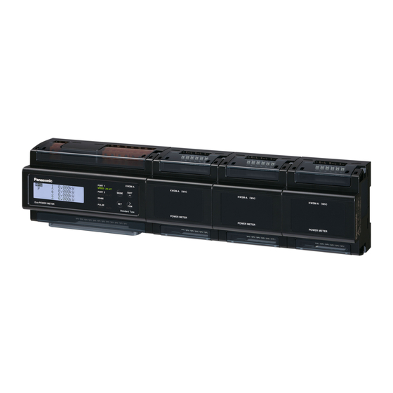
- Page 3 Introduction Thank you very much indeed for purchasing KW2M-A Eco-POWER METER. In this manual, we explain the usage of KW2M-A Eco-POWER METER in detail. Please use it correctly after understanding the content enough. Buy: www.ValinOnline.com | Phone 844-385-3099 | Email: CustomerService@valin.com...
-
Page 4: Table Of Contents
Table of Contents Cautions before using ..........................ⅰ Chapter 1 Unit’s Outline ..........................1 1.1 Model Number ............................1 1.2 Measurement outline ..........................1 1.3 Measurement items ..........................2 Chapter 2 Parts Name and Working ......................4 2.1 Parts Names ............................4 2.2 Key’s functions ............................ - Page 5 Chapter 6 Display of each Value ......................51 6.1 Working of Monitor display ........................51 6.2 Working of Monitor Display ........................52 6.2.1 Single-phase two-wire system ...................... 52 6.2.2 Single-phase three-wire system ....................54 6.2.3 Three-phase three-wire system ....................56 6.2.4 Three-phase four-wire system ......................
-
Page 6: Cautions Before Using
Cautions before using ■ About this product Eco-POWER METER is designed chiefly to manage saving energy. It is neither nor can it be legally used for billing. ■ Installation environment ◇Do not use the Unit in the following environments. ・Where the unit will be exposed to direct sunlight and where the ambient temperature is outside the range of -10 to 50 °C. - Page 7 ・External noise up to the level shown below is treated as noise voltage, but levels higher than this could lead to malfunctioning or damage to the internal circuit. Although the case is made from fireproof resin, do not mount it next to flammable materials. Between operating power supply terminals Noise voltage 1,500V...
- Page 8 ■ Precautions on using networks This product supports various network connections therefore it is likely to be subject to the following security risks. 1. Leakage and outflow of information via this product 2. Illegal operation by third party with malicious acts 3.
-
Page 9: Chapter 1 Unit's Outline
KW2M-A Eco-POWER METER Chapter 1 Unit’s Outline With KW2M-A Eco-POWER METER, electrical power (voltage, current, etc.), power factor, frequency, etc. are measured using AC voltage and AC current input via one of the following systems: single-phase two-wire system, single-phase three-wire system, three-phase three-wire system or three-phase four-wire system. -
Page 10: Measurement Items
1.3 Measurement items Item Unit Display data range Active Present value Instantaneous Reactive -999.99G to 999.99G Max. value power Min. value Apparent Active Total integral power Reactive varh 0.000k to 9999.9P Present value (import) Apparent Total integral Active power 0.000k to 9999.9P Present value Reactive varh... - Page 11 ・Demand Item Unit Display data range Active Reactive Apparent Present value Present demand 0.000k to 999.9M Max. demand Active (export) Reactive (export) Current * Please use this demand function as your standard. The demand value calculated with this function is not guaranteed. <Glossary>...
-
Page 12: Chapter 2 Parts Name And Working
Chapter 2 Parts Name and Working 2.1 Parts Names <Front> Power supply Voltage input terminals terminals Operation keys Display Indicators <Bottom view> RS485 Ethernet port communication Left: port 1 terminals Right: port 2 Pulse I/O terminals Current input terminals 2.2 Key’s functions Functions Measuring mode Shift to setting mode... -
Page 13: Chapter 3 Wiring
Chapter 3 Wiring Be sure to wire correctly according to the terminal arrangement and wiring diagrams. Please connect a fuse or a breaker to power supply part for safety reasons and to protect the device. This has no built-in power switch, circuit breaker or fuse for measured voltage input parts. Therefore it is necessary to install them in the circuit near this unit. -
Page 14: Measured-Circuit
・ Power source system is the electrical power system from one power source (normally one transformer). ・KW2M-A can measure 1-system max. 24-circuit of 1P2W system and 1-system max. 8-circuit of 1P3W and 3P3W system by connecting a main unit and expansion units. -
Page 15: Connection Between The Main Unit And The Expansion Unit
3.3 Connection between the main unit and the expansion unit Turn off the power of main unit when connecting expansion units. Peel off connector label on the side before connecting. (Do not peel off connector labels when not connecting.) It expands by connecting each male connector to female connector. Female connector is on the other side of male connector. -
Page 16: Wiring Diagrams
3.4 Wiring Diagrams Please connect a breaker or a fuse to the power supply and voltage input part for safety reasons and to protect the device. ・Recommended breaker: 3 to 15A (IEC approved or UL Listed) ・Recommended fuse : Time-lag fuse rated current 2A (IEC approved or UL Listed) Grounding the secondary side of VT (Voltage transformer) and CT (Current transformer) is not necessary with low-voltage circuit. - Page 17 Three-phase four-wire system *3 CTs are needed to measure three-phase four-wire system. *6 CTs are needed to measure 2-circuit. Vn terminal should be connected to N-phase which is grounded. ◆When measuring a load with exceed input voltage Voltage transformer (VT) is needed when you measure a load with over input voltage. Use a VT, those secondary voltage rating is 110V.
-
Page 18: How To Attach The Current Transformer (Ct)
3.5 How to attach the Current Transformer (CT) DANGER ●Never open the secondary circuit of CT under applying current to load. ・Use CT that the secondary side current is 5A or 1A. ・One CT is needed when measuring 1-circuit of 1P2W. Two CTs are needed when measuring 1P3W/3P3W (4 CTs for 2-circuit).Three CTs are needed when measuring 3P4W (6 CTs for 2-circuit). - Page 19 (1) Power off the measured devices. (2) Install applicable CT. (3) Connect CT to the terminal block. (4) After confirm all wiring correct, turn on the power of the load and KW2M-A. (Connection example) ◆How to set the parameters for CT (1) Select CT type (CT-T) according to the using CT.
-
Page 20: For Input Connection
3.6 For Input Connection ●Pulse input ・Contact input Use highly reliable metal plated contacts. Since the contact’s bounce time leads directly to error in the count value, use contacts with as short a bounce time as possible. In general, select 30Hz for max.counting speed. -
Page 21: Rs485 Communication
・To avoid noise, separate the transmission line from high-voltage line (power supply, voltage line). Terminal Terminal station station (Fig.1) Correct wiring ○ Incorrect wiring × ◆How to connect KW2M-A (2-wire) and KW9M (3-wire) Buy: www.ValinOnline.com | Phone 844-385-3099 | Email: CustomerService@valin.com... -
Page 22: Low Voltage Directive
Recommended Cable Use the transmission cables shown below for Eco-POWER METER RS485 communication system. Conductor Insulator Cable Resistance Cable Applicable cable Size Material Thickness diameter (at 20℃) HITACHI 1.25 mm Max. Approx. KPEV-S (AWG16) Max.16.8Ω/km Polyethylene 0.5 mm 8.5 mm 1.25 mm ×1P or more... -
Page 23: Symbol List
3.10 Symbol List Symbol Explanation AC Voltage DC Voltage CE Mark Confirmation of conformity of the product with the applicable EU directives and compliance with the essential requirements contained in these directives Protective insulation, device with protection class II Products with this mark comply with both the Canadian and the American requirements Phone: 800.894.0412 - Fax: 888.723.4773 - Web: www.ctiautomation.net - Email: info@ctiautomation.net Buy: www.ValinOnline.com | Phone 844-385-3099 | Email: CustomerService@valin.com... -
Page 24: Chapter 4 Settings
Chapter 4 Settings You can set basic parameters for measuring using the keys on Eco-POWER METER. For the parameters for other functions, use Web browser to set. (URL:http//xxx.xxx.xxx.xxx/setup/index.ntm Put the setting IP address to ‘xxx.xxx.xxx.xxx’) After wiring Eco-POWER METER and CT, power on and set the parameters for power measurement, Eco-POWER METER can measure the electric power. - Page 25 ◆Parameters for pulse input ○: Available -: Not available Setting Item Range Initial value Keys Web Pulse input 30, 2000 Pre-scale 0.001 to 100.000 1.000 0.001, 0.01, 0.1, 1, 10, 100 (kWh/1pulse) Stand-by power, Active power, Reactive power, Apparent power, Over current, Under current, Power interruption, Power factor, Unit for...
- Page 26 ○: Available -: Not available Setting Item Range Initial value Keys Web Voltage harmonics alarm threshold (ON/OFF) (OUT1,OUT2) Current harmonics alarm threshold (ON/OFF) 0.00 to 400.0 [%] 400.00 (OUT1,OUT2) Current THD alarm threshold (ON/OFF) (OUT1,OUT2) Voltage THD alarm threshold (ON/OFF) (OUT1,OUT2) Voltage unbalancing alarm threshold (ON/OFF) -...
- Page 27 ◆Parameters for communication (Ethernet) ○: Available -: Not available Setting Item Range Initial value Keys Web Available, Not available Available MEWTOCOL Protocol TCP,UDP - Port number 1024 to 65535 9094 Available, Not available Available MODBUS(TCP) Protocol TCP,UDP - Port number 502,1024 to 65535 Yes (available), DHCP...
-
Page 28: Setting Flow
4.1 Setting Flow Arrow mark means press each key <MODE> <ITEM/>> <SET> <SHIFT/∧> Items with * are only for Main unit-CH1. Measuring value display Enter password Setting mode 【Power 【Communication】 【Communication】 measurement】 (RS485) (Ethernet) 【Optional functions】 【Password】 (To next page) Phase/Wire DHCP setting *2 Protocol... - Page 29 Setting mode 【Optional functions】 【Password】 【Communication】 (From previous page) Auto-off Password setting Display update cycle Reset all integral value Reset count value Reset integral value 1 Reset hour meter Reset integral value 2 Reset logging data Reset integral value 3 Version Setting confirmation Setting confirmation...
-
Page 30: Password Entry
4.2 Password entry It is necessary to enter password to shift to setting mode. Enter [0000] and shift to password setting mode when you set password at the first time. *When setting password, be careful for handling and note it. Press <MODE>... -
Page 31: Password Initialize
4.3 Password initialize When you forget the password, initialize it in the following procedures. (Initial: [0000]) It is impossible to decode the set password. Press <MODE> and it shifts to password entry window. Measuring value display ↓<MODE> P a s s o r d Press <MODE>... -
Page 32: How To Set By Keys
4.4 How to Set by Keys ■Set before measuring. Select setting item with <ITEM/>> and press <SET>, and the value will be blinking. Set with <ITEM/>> and <SHIFT/∧>. When you select [Yes] with the confirmation window and press <SET>, the setting values are settled. Setting items with (※) can be set to each CH and each unit. -
Page 33: Settings For Communication (Rs485)
4.4.2 Settings for communication (RS485) Protocol Select protocol of main unit via serial communication (RS485). *When protocol is changed, device number, transmission speed (baud rate), transmission format, stop bit and response time will be initialized. Press <ITEM/>>, <SHIFT/∧> to select. S 4 8 5 [Set list] P r o t o c o l... - Page 34 Transmission format Select serial communication (RS485) transmission format (Data length, Parity). Define the transmission format according to the master’s (PLC etc.). Press <ITEM/>>, <SHIFT/∧> to select. S 4 8 5 F o r [Set list] 8b-o (8bit odd), 8b-n (8bit none), 8b-E (8bit even) 8 b i t - o (initial: 8b-o) Stop bit...
-
Page 35: Settings For Communication (Ethernet)
4.4.3 Settings for communication (Ethernet) DHCP setting Select DHCP for Ethernet communication. Press <ITEM/>>, <SHIFT/∧> to select. E t h e r n e t D H C [Set list] Yes (available), No (not available) (initial: No) IP address *It skips this item when [Yes] is set for DHCP setting. Set IP address for Ethernet communication. - Page 36 Default Gateway *It skips this item when [Yes] is set for DHCP setting. Set default gateway for Ethernet communication. Press <ITEM/>>, <SHIFT/∧> to set. E t h e r n e t e f u a l t a t e [Set range] 0.
-
Page 37: Settings For Optional Functions
4.4.4 Settings for optional functions Auto-off Display backlight turns off automatically when there is no key operation for a long time. After it passes the setting time, backlight will turn off. Press <ITEM/>>, <SHIFT/∧> to set. p t i o n A u t o [Set range] 0 to 99 min. - Page 38 Reset integral value 2 *It skips this item when [Yes] is selected for reset all integral value. Reset the integral power of 2CH/2-phase (active, reactive, apparent) and integral export power of 2CH/2-phase (active, reactive). Press <ITEM/>>, <SHIFT/∧> to select. p t i o n e s e t [Set list] Yes, No (initial: No) Y e s...
- Page 39 Reset count value *It skips this item when [Yes] is selected for reset all integral value. Reset the count value. Press <ITEM/>>, <SHIFT/∧> to select. p t i o n e s e t o u n t [Set list] Yes, No (initial: No) Y e s Reset : [Yes]...
-
Page 40: Password Setting
4.4.5 Password setting Password setting You can set password for changing the settings. It is necessary to enter the password before moving the setting mode. We recommend you to set password to avoid unexpected change. P a s s o r d Press <SET>... -
Page 41: Confirmation Window
4.4.6 Confirmation window Press <MODE> at any setting window and it shifts to confirmation window. Setting mode ↓<MODE> SHIFT S e t A l l S e t A l l ITEM Y e s > Confirm the change: [Yes] Cancel the change: [No] (initial: No) <SET>... -
Page 42: How To Set By Web Browser
4.5 How to Set by Web browser You can set by using Web browser. Access to ‘http://xxx.xxx.xxx.xxx/setup/index.htm’. Put the setting IP address to ‘xxx.xxx.xxx.xxx’. It is necessary to enter user name and password to access the website. (Initial user name: admin, initial password: admin) It may take time to get the website according to the communication environment. -
Page 43: Settings For Power Measurement
4.5.2 Settings for Power Measurement Item Description Select unit and CH Select unit and CH to set. Phase/Wire system Select phase and wire system to power measurement. <List> 1P2W, 1P3W, 3P3W, 3P4W (initial: 1P2W) Cutoff current Set a ratio of current for rated current used for cutoff that is not measured. - Page 44 Item Description Set parameters of CT. <Range> Primary side : 1 to 65535 (initial:5) Secondary side: 5 (5A), 1 (1A) (initial: 5) Set parameters of VT when VT is used. When VT is not used, set parameters of rated voltage to measure.
-
Page 45: Settings For Demand And Power Rates
4.5.3 Settings for Demand and Power Rates Click ‘ ’ to shift window of ‘Demand Setup’ and ‘Conversion rate Setup’. [Demand Setup] Item Description Power demand type Select type of power demand measurement. <List> Sliding block, Fixed block (initial: Sliding block) Power demand interval Set interval time to use for power demand measurement. - Page 46 [Conversion rate Setup] Item Description Conversion rate Setup Set the conversion rate per integral active power (import and export) 1 kWh. < Range > P/kWh : 0.01 to 99.99 (initial:10.00) -P/kWh : 0.01 to 99.99 (initial:10.00) Phone: 800.894.0412 - Fax: 888.723.4773 - Web: www.ctiautomation.net - Email: info@ctiautomation.net Buy: www.ValinOnline.com | Phone 844-385-3099 | Email: CustomerService@valin.com...
-
Page 47: Settings For Pulse Input
4.5.4 Settings for Pulse Input Item Description Max counting speed Select pulse input max. counting speed. < List > 30Hz, 2kHz (initial:30Hz) Pre-scale Set pre-scale value used to convert count value of pulse input. < Range > 0.001 to 100.00 (initial:1.000) Phone: 800.894.0412 - Fax: 888.723.4773 - Web: www.ctiautomation.net - Email: info@ctiautomation.net Buy: www.ValinOnline.com | Phone 844-385-3099 | Email: CustomerService@valin.com... -
Page 48: Settings For Pulse Output
4.5.5 Settings for Pulse Output It uses the measurement value of main unit CH1 for pulse output CH1, it uses the measurement value of main unit CH2 for pulse output CH2. [Integral power pulse] Item Description Select CH * Select CH to set. Output type Select pulse output type. - Page 49 [Alarm] With checks to several boxes, it output alarm when it meets one of these conditions. Item Description Select CH * Select CH to set. Output type Select pulse output type. < List > Integral power pulse, Alarm, General output (initial: Integral power pulse) Stand-by power Select phase to monitor and set threshold to use for output.
- Page 50 Item Description Power factor Select phase to monitor and set threshold to use for output. *Select ‘All’ when measuring 3P3W. < List & Range > Target phase:Phase1, Phase2, Phase3, ALL (initial: ALL) OFF threshold : 0.00 to 9999999999.99 (initial: 9999999999.99) ON threshold : 0.00 to 9999999999.99 (initial: 9999999999.99) Count value Set a value of count to use for alarm output.
-
Page 51: Settings For Ethernet And Rs485 Communication
4.5.6 Settings for Ethernet and RS485 communication Click ‘ ’ to shift window of ‘Ethernet Setup’ and ‘RS485 Setup’. [Ethernet Setup] Item Description IP address Select setting method of IP address. When you set manually, IP address, subnet mask and default gateway can be set by yourself. - Page 52 [RS485 Setup] Item Description Protocol Select communication protocol < List > MEWTOCOL, MODBUS RTU (initial: MEWTOCOL) Device number Set device number. < Range > MEWTOCOL:1 to 99 MODBUS RTU:1 to 247 Transmission speed Select transmission speed. < List > 2400, 4800, 9600, 19200, 38400, 57600, 115200bps (initial:19200) Transmission format Select transmission format.
-
Page 53: System Setup
4.5.7 System setup [System setup] Item Description Setting File It saves setup conditions of Eco-POWER METER to your PC and it writes setup conditions, which are saved in PC, to Eco-POWER METER. <Item> Export: Save setup conditions of Eco-POWER METER to PC. Import: Read out setup conditions saved in PC. - Page 54 [Reset Data] Item Description Select unit and CH Select unit and CH to reset. Select item Select data item to reset. After selecting item, click ‘Reset’ to reset. Phone: 800.894.0412 - Fax: 888.723.4773 - Web: www.ctiautomation.net - Email: info@ctiautomation.net Buy: www.ValinOnline.com | Phone 844-385-3099 | Email: CustomerService@valin.com...
-
Page 55: Chapter 5 Various Functions
Chapter 5 Various Functions 5.1 Power quality measurement and logging function KW2M-A Eco-POWER METER can measure harmonics and THD for power quality measurement, therefore it is helpful to improve the power quality. [Max. demand] Maximum value of measured demand value (active, reactive, apparent, active (export), reactive (export), current)) are considered to the max. -
Page 56: Power Alarm
5.2.8 Power alarm When it exceeds the setting instantaneous electric power (active, reactive, apparent, active (export), reactive (export)), pulse output turns on in order to notice. When it falls below, the output turns off. 5.2.9 Other alarms Output turns on or off according to each alarm setting. PF alarm, over frequency alarm, under frequency alarm, voltage harmonics alarm, current harmonics alarm、voltage THD alarm, current THD alarm, voltage unbalancing alarm, current unbalancing alarm, power demand alarm, current demand alarm... -
Page 57: Demand Function
5.4 Demand function You can select demand calculation methods for KW2M-A Eco-POWER METER from the bellows. ・According to IEC61557-12 1. Sliding block interval demand 2. Fixed block interval demand 3. Current demand Please use this simple demand function as your standard. The value is not guaranteed. -
Page 58: Current Demand
5.4.2 Current Demand Current demand calculates the demand based on a thermal demand meter. Current demand = (Average of current – last current demand value) × 90%(fixed) + Last current demand value In case of that a stable current flows for interval time, 90% of current value is displayed. time interval 5.4.3 Max. -
Page 59: Chapter 6 Display Of Each Value
Chapter 6 Display of each Value 6.1 Working of Monitor display 【Shift the display mode】 Press <SHIFT/∧> during pressing <MODE>, it shifts measuring mode, logging mode and demand mode. Press <MODE> to shift the setting mode. initial Power monitoring <MODE> mode <MODE>+<SHIFT/∧>... -
Page 60: Working Of Monitor Display
6.2 Working of Monitor Display 6.2.1 Single-phase two-wire system Arrow mark shows to press each key. <ITEM/>> SHIFT/▽> Instantaneous power Active Reactive Apparent Total integral power Active Reactive Apparent Total integral export power Active Reactive Current Voltage Power factor Frequency Current THD Voltage THD Current n-order harmonics... - Page 61 From the previous page Conversion value P (integral power) Conversion value –P (integral export power) Return to instantaneous power Buy: www.ValinOnline.com | Phone 844-385-3099 | Email: CustomerService@valin.com...
-
Page 62: Single-Phase Three-Wire System
6.2.2 Single-phase three-wire system Arrow mark shows to press each key. <ITEM/>> <SHIFT/∧> Instantaneous power Active Reactive Apparent Total integral power Active Reactive Apparent Total integral export power Active Reactive Current Voltage Phase-voltage Line-voltage Power factor Frequency Current unbalancing Voltage unbalancing Current THD Voltage THD Phase-voltage THD... - Page 63 From the previous page Phase-voltage n-order Harmonics order order order ・・・・・ Line-voltage n-order Harmonics order order order ・・・・・ Pulse input value Conversion value P (integral power) Conversion value -P (integral export power) Return to instantaneous power Buy: www.ValinOnline.com | Phone 844-385-3099 | Email: CustomerService@valin.com...
-
Page 64: Three-Phase Three-Wire System
6.2.3 Three-phase three-wire system Arrow mark shows to press each key. <ITEM/>> <SHIFT/∧> Instantaneous power Active Reactive Apparent Total integral power Active Reactive Apparent Total integral export power Active Reactive Current Line-voltage Power factor Frequency Current unbalancing Voltage unbalancing Current THD Voltage THD Current n-order Harmonics order... - Page 65 From the previous page Line-voltage n-order Harmonics order order order ・・・・・ Pulse input value Conversion value P (integral power) Conversion value -P (integral export power) Return to instantaneous power Buy: www.ValinOnline.com | Phone 844-385-3099 | Email: CustomerService@valin.com...
-
Page 66: Three-Phase Four-Wire System
6.2.4 Three-phase four-wire system Arrow mark shows to press each key. <ITEM/>> <SHIFT/∧> Instantaneous power Active Reactive Apparent Total integral power Active Reactive Apparent Total integral export power Active Reactive Current Current N-phase current Voltage Phase-voltage Line-voltage Power factor Frequency Current unbalancing Voltage unbalancing Current THD... - Page 67 From the previous page Current n-order Harmonics order order order ・・・・・ Phase-voltage n-order Harmonics order order order ・・・・・ Line-voltage n-order Harmonics order order order ・・・・・ Pulse input value Conversion value P (integral power) Conversion value -P (integral export power) Return to instantaneous power Buy: www.ValinOnline.com | Phone 844-385-3099 | Email: CustomerService@valin.com...
-
Page 68: Instantaneous Power
6.2.5 Instantaneous power ・The present instantaneous power of all phases or all circuits is displayed. ・Press <SHIFT/∧> to change active, reactive and apparent. <1P2W/1P3W/3P4W> Active Reactive SHIFT 1 2 3 . 4 5 k k v a r 1 - 2 k v a r k v a r Σ... -
Page 69: Total Integral Power
6.2.6 Total integral power ・The present total integral power is displayed. ・Press <SHIFT/∧> to change active, reactive and apparent. Active Reactive SHIFT 1 . 2 3 4 k 1 . 2 3 4 k v a r h Apparent SHIFT 1 . -
Page 70: Current
6.2.8 Current ・The present current value is displayed. (N-phase current is displayed for 3P4W.) SHIFT 1 - 2 ・It measures from 0.1% of CT secondary current. ・When input current exceeds 200% or the display range, it displays “- - - - -“. Check and confirm the measurement environment. -
Page 71: Power Factor
6.2.10 Power factor ・The present power factor of the load is displayed. <1P2W/1P3W/3P4W> <3P3W> 1 2 3 *Power factor operation is a method assuming balanced load. The error might be big when it measures unbalanced load. 6.2.11 Frequency ・The present frequency is displayed. <1P2W/1P3W/3P4W>... -
Page 72: Current Thd
6.2.14 Current THD ・The present THD for current is displayed. 6.2.15 Voltage THD ・The present THD for voltage displayed. 6.2.16 Current n-order Harmonics ・The present current n-order harmonics is displayed. ・Press <SHIFT/∧> to change display. order, 3 order, 4 order ・・・・・ up to 31 order - I 2 6.2.17 Voltage n-order Harmonics... -
Page 73: Pulse Input Value
6.2.18 Pulse Input Value ・The present pulse input value is displayed. ・Pulse input status (ON or OFF) is confirmed via communication. (MEWTOCOL and MODBUS) Pulse input 1 2 3 4 5 6 7 8 9 0 1 *Turn on the unit during IN1 is shorted, first 1-pulse is not counted. After that, when pulse is input pulse it count the pulse. -
Page 74: Conversion Value For Integral Export Power
6.2.20 Conversion value for integral export power ・The conversion value for the present integral export active power (-P) is displayed. (Only total conversion value is displayed for 3P3W.) ・Press <SHIFT/∧> to change total, phase 1 (1 circuit), phase 2 (2 circuit) and phase 3 (3 circuit). -
Page 75: Working Of Logging Mode
6.3 Working of Logging Mode Each measured value is displayed as below. It differs according to the selected phase/wire system. Arrow mark shows to press each key. <ITEM/>> <SHIFT/∧> <SET> <SET>+<ITEM/>> Max. Active power demand Max. Reactive power demand Max. Apparent power demand Max. -
Page 76: Working Of Demand Mode
6.4 Working of Demand Mode Each measured value is displayed as below. It differs according to the selected demand type. 6.4.1 Block Interval Demand (Sliding block、fixed block) Arrow mark shows to press each key. <ITEM/>> <SHIFT/∧> <SET> <SET>+<ITEM/>> Present demand Active power Reactive power Apparent power... - Page 77 Present power demand ・Each demand value is displayed. ・Press <SHIFT/∧> to change active power, reactive power, apparent power. Active power present demand Reactive power present demand SHIFT 1 2 3 . 4 5 k 1 2 3 . 4 5 k v a r Apparent power present demand SHIFT 1 - 1...
- Page 78 Pulse conversion value for integral power ・Present value of pulse conversion value for integral power. P L S 1 2 3 . 4 5 k Present current demand ・Present value of current demand is displayed. 1 2 . 3 4 5 A Buy: www.ValinOnline.com | Phone 844-385-3099 | Email: CustomerService@valin.com...
-
Page 79: Chapter 7 Specifications
Chapter 7 Specifications 7.1 General specification (for main unit and expansion unit) Supply voltage range 100 to 240V AC Rated frequency 50/60Hz Nominal power consumption Approx. 15VA (240V AC at 25℃) Inrush current 30A or less (240V AC/DC at 25℃) Allowable momentary 10ms power-off time... -
Page 80: Measurement Specifications
7.2 Measurement Specifications Power measurement (for main unit and expansion unit) 2-circuit of 1-system Measured circuit number Main unit (6-circuit of 1-system for 1P2W) 2-circuit of 1-system Expansion unit (6-circuit of 1-system for 1P2W) 8-circuit of 1-system (24-circuit of 1-system for 1P2W) Max. -
Page 81: Output Specifications (Only For Main Unit)
7.3 Output Specifications (only for main unit) Number of output point 2 points *Insulate between output terminals Insulation method MOSFET relay Output type Output capacity 100mA, 30V AC/DC ・Pulse by integral power Output mode (OUT1/OUT2) ・Output by alarm or events (set with setting mode) Pulse width 1 to 100ms... -
Page 82: Input Specifications (Only For Main Unit)
7.4 Input Specifications (only for main unit) Number of input point 1 point Insulation method Designated insulation for input (insulate to the other functions) Input method Contact/ non-voltage a contact or open-collector ・Impedance; Max. 1kΩ (when short-circuit current: Max. 10mA) Input signal Non-voltage ・Residual voltage when shorted;... -
Page 83: Demand Monitor And Control Specifications (Common To 9, 10)
7.5 Demand monitor and control specifications (common to 9, 10) IEC61557-12 demand 1. Sliding block interval Demand type 2. Fixed block interval 3. Current demand Current transformer input Power input type Pulse input *1 (set with setting mode) Demand span 1 to 60 min. -
Page 84: Self-Diagnostic
7.7 Self-diagnostic When error is happened, error code will be indicated. List of Error Code Name Action to take W0001 DHCP server access error Connect to DHCP server. W0002 Obtain the illegal IP address by DHCP Confirm DHCP server. server W0003 IP address duplication Change IP address. -
Page 85: Chapter 8 Mounting
Chapter 8 Mounting 8.1 Dimensions 8.1.1 Main unit (Unit: mm) (Clearance: ±1.0) 8.1.2 Expansion unit Buy: www.ValinOnline.com | Phone 844-385-3099 | Email: CustomerService@valin.com... - Page 86 Revision History Issue Date Manual No. Content of revision June, 2015 WUME-KW2MA-01 First edition Buy: www.ValinOnline.com | Phone 844-385-3099 | Email: CustomerService@valin.com...