
Related Manuals for ABB i-bus DALI-Gateway DG/S 8.1


Summary of Contents for ABB i-bus DALI-Gateway DG/S 8.1
- Page 1 ® Product manual ABB i-bus DALI-Gateway DG/S 8.1 Intelligent Installation Systems...
- Page 2 Despite checking that the contents of this document match the hardware and software, deviations cannot be completely excluded. We therefore cannot accept any liability for this. Any necessary corrections will be inserted in new versions of the manual. Please inform us of any suggested improvements. E-mail: eib.hotline@de.abb.com...
-
Page 3: Table Of Contents
Contents Page Introduction ................Product and functional description ......... What is DALI? ................1.2.1 DALI as stand-alone system – characteristics – ..... 1.2.2 Behaviour of the DALI devices in the event of an operating power failure/recovery ........1.2.3 Behaviour of the DALI devices in the event of a DALI power failure ............ - Page 4 Contents Page 4.3.6 Parameter window: Status ............Behaviour in the event of malfunctions ........4.4.1 Behaviour on voltage failure ............ 4.4.2 Behaviour on voltage recovery ..........Seite überarbeitet, Application and planning ............bitte überprüfen, danke! 8-bit-scene ................Coloured light with LED technology and DALI ......Staircase lighting function ............
-
Page 5: Introduction
DALI. To be familiar with the Engineering Tool Software ETS is a prerequisite. ABB STOTZ KONTAKT GmbH retains the legal right to the copyright of this manual. -
Page 6: Product And Functional Description
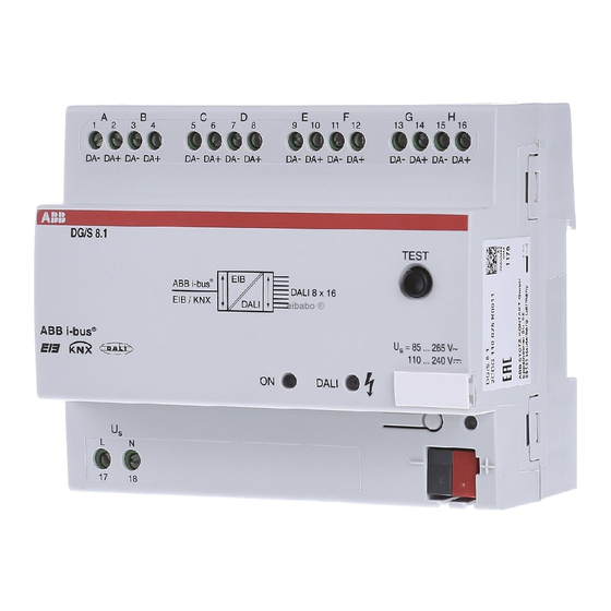
DALI-Gateway DG/S 8.1 is a DIN rail mounted device with functional description a width of 6 modules in the proM design for insertion in the distribution board. The connection to the ABB i-bus ® is established via a bus connection terminal at the front of the device. -
Page 7: What Is Dali
ABB i-bus ® Introduction What is DALI? The requirements for modern lighting technology are extremely varied. While previously lighting was only required for visual tasks, nowadays factors such as comfort, ambience, functionality and energy saving are in the foreground. Furthermore, a modern lighting system is increasingly being incorporated in the Facility Management (maintenance and preparation management) of the building installation. -
Page 8: Of An Operating Power Failure/Recovery
ABB i-bus ® Introduction A DALI power source (16 V DC) supplies the individual DALI devices, the DALI processor, controller, control devices or modules which are responsible for managing the scenes and groups in the DALI line. A separate relay or a calculation of the switching capacity is not required as the switching relay is integrated in the DALI ballast. -
Page 9: Dali Functional Description
DALI has established itself since 1999 as a company-neutral interface standard. It is possible to control fluorescent lamps, incandescent lamps, LEDs etc. via DALI, combine them into light scenes and to integrate them with the ABB i-bus ® DALI-Gateway DG/S 8.1 in the KNX building installation. - Page 10 ABB i-bus ® Introduction for 0 = off) below 126 (50% brightness, 3% luminous flux) are interpreted as the minimal lighting level. Together with the DALI Gateway following effect is to attend: For example on the ECG is a dimming zone from 3…100% printed, you have an ECG which can not drop under the minimal luminous flux of 3%.
-
Page 11: Special Features Of The Dali-Gateway Dg/S 8.1
ABB i-bus ® Introduction Special features of the With the DALI-Gateway DG/S 8.1, it is possible to utilise the benefits DALI-Gateway DG/S 8.1 of the DALI standard in the KNX building system technology. There is no time-consuming addressing of the individual DALI devices necessary. - Page 12 ABB i-bus ® Introduction Relay Ballast Dimmer Dimmer Ballast Ballast Ballast Ch. 1 Ch. 2 Ch. 3 Ch. 4 Ch. 5 Ch. 6 Ch. 7 Ch. 8 DALI-Gateway -Lighting DG/S 8.1 Operation Visualisation Shutter Heating Security Fig. 3: DALI-Gateway DG/S 8.1, Block diagram...
-
Page 13: Technical Data And Connection
The DALI-Gateway DG/S 8.1 has an AC or DC mains supply. The connection to the ABB i-bus ® in the device is established via the bus connection terminal. -
Page 14: Technical Data
ABB i-bus ® Technical data and connection Technical data Power supply – Operating voltage 85...265 V AC, 50/60 Hz 110 ... 240 V DC – Total power consumption from the system max. 12.5 W, at 230V AC and max. load –... -
Page 15: Application Program
Dim Slave Lightscenes Dynamic 8f/1.1 Note: ETS2 V1.3 or higher is required for programming. When using ETS3, a file of type “VD3” must be imported. The application program is stored in ETS2/ETS3 under ABB/Illumination/DALI/Dim Slave Lightscenes Dynamic 8f/1.1. Circuit diagram max. -
Page 16: Assembly And Installation
ABB i-bus ® Technical data and connection Assembly and installation The DALI-Gateway DG/S 8.1 is suitable for insertion in distribution boards or miniature housing for snapping onto 35 mm mounting rails, in accordance with EN 60 715. The accessibility of the device for operation, testing, inspection, maintenance and repair must be ensured. -
Page 17: Commissioning Requirements
AC or DC 230 V power supply. You require a PC or laptop ® with ETS (from ETS2 V1.3 onwards) and an interface to the ABB i-bus e.g. via RS232 or USB interface. 2.6.2 Supplied state The DALI-Gateway DG/S 8.1 is supplied with the physical address... -
Page 18: Functional Description
The essential functions and operation of the DALI-Gateway DG/S 8.1 are description explained in this section. System description The ABB i-bus ® DALI-Gateway DG/S 8.1 is the link between DALI equipment and the KNX. 8 DALI outputs (channels) can be connected to the DALI- Gateway DG/S 8.1 with a maximum of 16 per channel. -
Page 19: Manual Operation / Test Function
ABB i-bus ® Functional description Manual operation / The DALI Gateway is fitted with a test button. If the device is connected test function to the mains voltage, each DALI output can be switched on manually in sequence and then off again. -
Page 20: Dynamic Mode
ABB i-bus ® Functional description Dynamic mode The dynamic mode can be set individually for each channel. Timed bright- ness characteristics can be set and retrieved when required. If the operating mode is set to dynamic mode, the channel is able to implement a simple staircase lighting function as well as special lighting sequences for a daylight simulation. -
Page 21: Scene Dimming
ABB i-bus ® Functional description Scene dimming Scene dimming is possible with the DALI-Gateway DG/S 8.1 and the central command “Relative dimming” are described as follows: The set brightness values and the relative brightness differences of the indi- vidual channels are maintained during the central dimming process (object relative dimming, channels A…H). -
Page 22: Constant Lighting Control
ABB i-bus ® Functional description Constant lighting control Each DALI output (channel) of the DALI-Gateway DG/S 8.1 can be priority controlled in slave mode via a 1-byte brightness value (communication object: “Channel X - Set Brightness Value”). The “slave mode” is activated and deactivated via the 1-bit communication object “Channel X - Slave... -
Page 23: Burn-In Times
ABB i-bus ® Functional description Burn-in times In the case of lamps filled with gas, a burn-in time is recommended as solid or fluid additives in them must be evaporated before optimum operation can be achieved and an optimum internal pressure in the lamp is enabled. -
Page 24: Project Design And Programming
ABB i-bus ® Project design and programming Project design and The project design and programming of the DALI-Gateway DG/S 8.1 are described in this section. programming Starting the application Once the application “Dim Slave Lightscenes Dynamic 8f/1.1” has been imported in ETS, the communication objects described in this section are available, depending on the parameter setting. -
Page 25: Dali Output (Channel X) Communication Objects
ABB i-bus ® Project design and programming 4.2.1 DALI output (Channel X) The general communication objects which are available for each DALI out- communication objects put are described in the following section. Many communication objects are dynamic and are only visible if the corresponding parameters are activated in the application software. - Page 26 ABB i-bus ® Project design and programming Set Brightness Value Channel A 8 bit (EIS 6) DPT C, W 5.001 Channel X Set Brightness Value [EIS 6; 1-byte value]: The defined brightness value for the corresponding channel is received via this object. It can be set whether the channel jumps or dims to this value.
- Page 27 ABB i-bus ® Project design and programming Telegr. Fault Ballast Channel A 1 bit (EIS 1) C, R, T DPT 1.005 Channel X Telegr. Fault Ballast [EIS 1; 1-bit switching]: A fault signal which originates from one or more ballasts of the channel can be sent or read out via this object (e.g. for main- tenance purposes), depending on the parameter setting (Status parameter window).
-
Page 28: Central Communication Objects (Channels A
ABB i-bus ® Project design and programming 4.2.2 Central communication The following communication objects enable the central control of all DALI objects (Channels A...H) outputs (channels) A...H i.e. all outputs are controlled together. Fig. 11: Communication objects “Channels A...H” Function... - Page 29 ABB i-bus ® Project design and programming Set Brightness Value Channels A … H 8 bit (EIS 6) C, W DPT 5.001 Channels A ... H Set Brightness Value [EIS 6; 1-byte value]: The brightness value for all the channels is received via this object (central control). Telegrams which are received via this communication object (CO) take priority over commands which are received by the specific channel objects.
-
Page 30: Lightscene Communication Objects
ABB i-bus ® Project design and programming 4.2.3 Lightscene 16 lightscenes can be activated via the parameter setting. The scenes can communication objects be defined by the ETS entries or set individually by the user according to personal requirements via the individual object. It is possible for each scene to disable the overwriting of the brightness values during an ETS download. - Page 31 ABB i-bus ® Project design and programming With these communication objects, lightscenes can be stored individually e.g. with a push button or another operating device. Fig. 13: Communication objects “Store Lightscene x/y” Function Object name Data type Flags Store Scene...
- Page 32 ABB i-bus ® Project design and programming With these 1-byte communication objects, the 16 lightscenes are stored and recalled via a special code. Fig. 14 : Communication objects “Lightscenes 1...16”“ Function Object name Data type Flags Communication objects not assigned Control Scenes Lightscenes 1 ...
-
Page 33: General Communication Objects
ABB i-bus ® Project design and programming 4.2.4 General communication The following communication objects are only activated and visible if the objects corresponding parameter setting has been carried out. The KNX can be monitored with these communication objects. The number of DALI devices can be fixed for continious monitoring. - Page 34 ABB i-bus ® Project design and programming Telegr. Communication General 1 bit (EIS 1) C, W receive DPT 1.002 General Telegr. Communication receive [EIS 1; 1-bit switching]: The DALI Gateway can receive a “1” telegram via this communication object which another KNX device (e.g.
-
Page 35: Description Of The Parameters
ABB i-bus ® Project design and programming Description The parameters and parameter windows for the operation and programming of the parameters of the application “Dim Slave Lightscenes Dynamic 8f” are described in more detail in the following section. The number of parameter windows can vary depending on the parameter setting. -
Page 36: Parameter Window: General
ABB i-bus ® Project design and programming 4.3.1 Parameter window: The general behaviour and the behaviour in the event of a fault are defined General in the General parameter window. Fig. 17: General parameter window Channel setting: It is defined with this parameter whether the channels should be set individually or globally. - Page 37 ABB i-bus ® Project design and programming Reaction on DALI or EIB / KNX bus voltage recovery: It is defined with this parameter how the output channels or DALI devices react if the KNX supply voltage, the operating voltage and the DALI control voltage are restored.
- Page 38 ABB i-bus ® Project design and programming If the function “Burn in lamps” is activated and a “Burn in Lamps” telegram has been received, the lamps of the channel can only be operated at 0% (Off) or 100% brightness for the parameterised burn-in time. This applies regardless of the other dimming, ON/OFF and lightscene brightness values which have been set.
-
Page 39: Parameter Window: Channel
ABB i-bus ® Project design and programming 4.3.2 Parameter window: In the parameter window Channel X or Channels (for global channel Channel X configuration), the settings for the individual channels or for all the channels together are carried out. The parameter windows Channel B to H are only visible if the setting “individual”... - Page 40 ABB i-bus ® Project design and programming Minimal brightness value: The minimum brightness value which the DALI device should adopt when dimming darker or setting brightness values is defined via this parameter. The absolute minimal brightness value (back- ground brightness) which the ballast/lamp combination can adopt is ma- nufacturer-specific and typically lies between 1% and 5% of luminous flux.
- Page 41 ABB i-bus ® Project design and programming This means that the ON/OFF value is not achieved at the same time but there is no unnecessarily long delay until a lamp switches from e.g. 30% brightness to the OFF state. Setting brightness value turns channel on: If it should be possible to switch on from the OFF state via a dimming command “Set Brightness...
-
Page 42: 4.3.2.2 "Dynamic" Operating Mode
ABB i-bus ® Project design and programming 4.3.2.2 “Dynamic” operating mode Fig. 21: Parameter window Channel X – Dynamic operating mode If the operating mode is set to dynamic mode, the channel is able to implement e.g. staircase lighting functions or special lighting processes. - Page 43 ABB i-bus ® Project design and programming Any values can be set for the starting, hold and switch OFF values. It is therefore possible to implement very specific or special dimming processes e.g. daylight simulation. Initial brightness value when turned on: This parameter indicates the starting brightness value with which the DALI devices should switch on after receipt of an ON telegram.
-
Page 44: 4.3.2.3 „Slave" Mode
ABB i-bus ® Project design and programming 4.3.2.3 „Slave“ mode The DALI Gateway can also be operated as a slave. In slave mode, the channel is priority controlled via an 8-bit communication object. This opera- ting mode is activated and deactivated per channel (DALI output) as required via a communication object “Channel X - Slave Operation On / Off”. -
Page 45: Parameter Window: Central Function
ABB i-bus ® Project design and programming 4.3.3 Parameter window: The settings for the simultaneous control of all the channels (central control) Central function are carried out in the parameter window Central function. Fig. 23: Central function parameter window – Channels A..H... -
Page 46: Parameter Window: Scenes
ABB i-bus ® Project design and programming 4.3.4 Parameter window: The general settings for the lightscenes (maximum 16) are carried out in the Scenes Scenes parameter window. Fig. 24: Scenes parameter window - General scene parameters Activate lightscenes: The lightscenes (max. 16) are activated with this parameter. -
Page 47: Parameter Window: Scene X
ABB i-bus ® Project design and programming 4.3.5 Parameter window: The settings for the individual scenes are carried out in the parameter Scene X window Scene X (X = 1 to 16). The parameter window is only visible if the parameter “Activate lightscenes”... - Page 48 ABB i-bus ® Project design and programming Channel X: Lightscene value: This parameter indicates the brightness value as a percentage which is adopted by the DALI output and the connected DALI devices when the scene is retrieved. The lightscene value has the default setting of 50% brightness.
-
Page 49: Parameter Window: Status
ABB i-bus ® Project design and programming 4.3.6 Parameter window: The behaviour of the status and fault communication objects is defined Status in the Status parameter window. The detection of a fault can take up to 30 seconds depending on the number of electronic ballasts. - Page 50 ABB i-bus ® Project design and programming Send telegram “Fault Ballast”: In the setting “no”, the function and the communication objects are not available. In the parameter setting “only on read request”, the object value “Channel X - Telegr. Fault Ballast” can only be read out after a read request.
- Page 51 ABB i-bus ® Project design and programming Transmission / receive period: The parameter is only visible if “Send / receive communication telegram cyclically” is not set to “no”. The set period applies both to the time span between two telegrams which are sent by the DALI Gateway and to the time span in which a telegram should be received for bus monitoring.
-
Page 52: Behaviour In The Event Of Malfunctions
ABB i-bus ® Project design and programming Behaviour in the event This chapter describes the behaviour of the DALI gateway of the units that of malfunctions are connected to the gateway in the event of malfunctions like a failure of the bus or operating voltage. -
Page 53: Behaviour On Voltage Failure
ABB i-bus ® Project design and programming 4.4.1 Behaviour Failure of the operating voltage on voltage failure The failure of the operating voltage on the DALI Gateway is indicated by the green operating LED on the front of the device being extinguished. - Page 54 ABB i-bus ® Project design and programming Any scene sequences that have been started and the dynamic operating mode (e.g. staircase lighting function) continue to run if “no change” has been selected on the General parameter in the event of bus voltage failure.
-
Page 55: Behaviour On Voltage Recovery
ABB i-bus ® Project design and programming The 8-fold KNX DALI gateway, DG/S 8.1, interprets a failure of the operat- ing voltage of the DALI devices as a fault of the electronic ballast, since the DALI device does not reply anymore. Once the operating voltage is restored, the electronic ballast is switched on with maximal brightness (100%) as it is requested by the manufacturer. - Page 56 ABB i-bus ® Project design and programming KNX bus voltage recovery The behaviour of the DALI devices on recovery of the KNX bus voltage can be defined via the parameters. The parameter “Reaction on DALI or EIB / KNX bus voltage recovery” is available for this purpose in the General parameter window.
-
Page 57: Application And Planning
ABB i-bus ® Application and planning Application and The DALI Gateway can be used wherever modern lighting technology is required or requested. planning This can be simple office lighting, complex lighting control in hotel foyers or exhibition rooms as well as monitoring possibilities for the entire lighting system. -
Page 58: Coloured Light With Led Technology And Dali
ABB i-bus ® Application and planning Example: An KNX scene (no. 8) consisting of 4 lamps and 3 shutters which are con- nected to two DALI Gateways and 2 shutter actuators can be recalled via a single KNX telegram. The prerequisite is that all the participants of scene 8 are parameterised accordingly in their devices. -
Page 59: Staircase Lighting Function
ABB i-bus ® Application and planning Staircase lighting function A typical staircase lighting function can be parameterised in the dynamic operating mode of the DALI Gateway. The following parameter setting can be used whereby the “Dim period to reach brightness value before turned off”... -
Page 60: Facility Management
ABB i-bus ® Application and planning Facility Management One of the benefits of the DALI standard is the detection and reporting of ballast and lamp faults. This information can be displayed directly or routed to a control unit in order to arrange the appropriate maintenance or service procedures. -
Page 61: Assignment Of The Switch Sensor
ABB i-bus ® Application and planning The DALI Gateway from ABB opens up a variety of possibilities to the user Assignment of the switch for operating and adjusting the lighting in a convenient, individual and sensor targeted way. At the same time, a range of safety functions can be taken into account. - Page 62 ABB i-bus ® Application and planning Example 2 “Scene solution” The first push button controls channel A with lighting strip 1 and channel B with lighting strip 2. A short push button action switches the lighting strips on with the brightness value with which they were previously switched off (parameterised).
-
Page 63: Maintenance
ABB i-bus ® Maintenance Maintenance The maintenance instructions for the DALI-Gateway DG/S 8.1 are described in the following chapter. DALI-Gateway DG/S 8.1 The DALI-Gateway DG/S 8.1 is maintenance-free. In the event of damage (e.g. caused during transportation, storage), no repairs may be carried out. -
Page 64: Appendix
Appendix Overview DALI devices ABB offers a large collection of DALI devices. There are ECG (electrical ballasts) for T5, T6 and compact fluorescent lamps (e.g. ECG DALI-T5 or TC-L), electronic transformers for low voltage halogen lamps (e.g. ETR one4all), dimmers (e.g. DALI-DU/E300), DALI switch actua- tors (e.g. -
Page 65: Key Table For 8-Bit Scene Telegram
ABB i-bus ® Appendix Key table The table indicates the telegram code of an 8-bit scene in hexadecimal and for 8-bit scene telegram binary code for the first 16 scenes, which are relevant for the DALI Gateway. When retrieving or storing a scene, the 8-bit value must be sent. -
Page 66: Conversion Of Older Application Program
ABB i-bus ® Appendix Conversion of A Conversion of application program V1.0 to V1.1 is possible. older application program With the aid of the conversion it is possible from ETS3 to accept the param- eters and group addresses from previous application programs. -
Page 67: Definition Of Terms
ABB i-bus ® Appendix Definition of terms 1...10 V technology Analogue interface for controlling electrical equipment. The brightness is controlled in lighting technology via a polarised voltage at the control input. This voltage is made available by the ballast. Individual addressing and direct addressing of the individual devices is not possible. - Page 68 ABB i-bus ® Appendix The KNX controls, switches and monitors numerous functions in the buil- dings. These include lighting control, maximum-demand monitoring, tempe- rature control, emergency and standby operation, fan control, shutter/roller blind control, timed/remote control, display/logging as well as monitoring and reporting.
- Page 69 ABB i-bus ® Appendix Group A group in lighting technology is the number of electrical devices which can be controlled and/or switched together. Groups can be formed via hardware with the corresponding wiring or via software with the corresponding addressing.
-
Page 70: List Of Diagrams
® ABB i-bus Appendix Fig. 1 DALI-Gateway DG/S 8.1 ......... . -
Page 71: Further Information About Dali
Further information Further information about DALI and its possibilities in lighting technology: about DALI ABB DALI manual DALI manual of the AG DALI, which is part of the ZVEI This manual and further information about DALI can be found on the AG DALI Internet page under “http://www.dali-ag.org“... -
Page 72: Specification Text
ABB i-bus ® Appendix A. 8 Specification text Item Qty Description of products and services Price per Amount unit DALI-Gateway, 8-fold, MDRC Carry: The 8-fold DALI Gateway is used to control DALI devices (electronic ballasts, transformers, etc.). A maximum of 128 DALI devices can be connected to 8 independent channels. -
Page 73: Ordering Information
ABB i-bus ® Appendix Ordering information Short code Designation Price Unit Pack 40 16779 group weight unit Order no. pce. DG/S 8.1 DALI-Gateway, 8-fold, MDRC 2CDG 110 025 R0011 58582 8 0.190 1 Table 11: Ordering information for the DALI-Gateway, 8-fold, MDRC A.9.1 Scope of supply... - Page 74 ABB i-bus ® Notes...
- Page 75 The information in this leaflet is subject to change without further notice. Your KNX-Partner...