ABB ARR600 User Manual
Wireless i/o gateway
Hide thumbs
Also See for ARR600:
- Product manual (20 pages) ,
- Quick start manual (4 pages) ,
- Quick start manual (4 pages)
Table of Contents
Advertisement
Quick Links
Advertisement
Table of Contents

Related Manuals for ABB ARR600


Summary of Contents for ABB ARR600
- Page 1 — Wireless I/O Gateway ARR600 User Manual...
- Page 3 Document ID: 1MRS758458 Issued: 2021-06-04 Revision: F Product version: 3.4.7 © Copyright 2021 ABB. All rights reserved...
- Page 4 Copyright This document and parts thereof must not be reproduced or copied without written permission from ABB, and the contents thereof must not be imparted to a third party, nor used for any unauthorized purpose. The software or hardware described in this document is furnished under a license and may be used, copied, or disclosed only in accordance with the terms of such license.
- Page 5 ABB is not liable for any such damages and/or losses.
- Page 6 Safety information Dangerous voltages can occur on the connectors, even though the auxiliary voltage has been disconnected. Non-observance can result in death, personal injury or substantial property damage. Only a competent electrician is allowed to carry out the electrical installation. National and local electrical safety regulations must always be followed.
-
Page 7: Table Of Contents
Intended audience................5 Product documentation...............5 Product documentation set............5 Document revision history............. 5 Related documentation..............6 Symbols and conventions..............6 Symbols..................6 Document conventions..............7 Section 2 ARR600 overview.............9 Overview.....................9 Physical interfaces................10 Front panel.................. 10 Back panel...................12 Side panel..................13 Product information label ..............14 Firmware version................14 Section 3 Physical connections............15... - Page 8 Modbus register maps..............47 Section 11 I/O interface..............49 Digital connector IO-1 pins............... 49 Digital input (IO-1)............... 50 Digital output (IO-1)..............50 Digital and analog connector IO-2 pins..........51 Digital input (IO-2)............... 52 Digital output (IO-2)..............53 Analog input (IO-2)..............53 ARR600 User Manual...
- Page 9 Table of contents DC output..................53 Section 12 Troubleshooting..............55 Common troubleshooting issues............55 Viewing the system log..............55 Section 13 Technical data..............57 Section 14 Glossary................. 61 ARR600 User Manual...
-
Page 11: Section 1 Introduction
The personnel is expected to be familiar with basic working principles of Internet technology. Product documentation 1.3.1 Product documentation set Product series- and product-specific manuals can be downloaded from the ABB Web site abb.com/mediumvoltage. 1.3.2 Document revision history Document revision/date... -
Page 12: Related Documentation
Wireless I/O Gateway ARR600 RTU ARR600 RTU application 1MRS758855 configuration guide Technical Note configuration Product series- and product-specific manuals can be downloaded from the ABB Web site abb.com/mediumvoltage. Symbols and conventions 1.4.1 Symbols The electrical warning icon indicates the presence of a hazard which could result in electrical shock. -
Page 13: Document Conventions
Select Main menu/Settings. • Parameter names are shown in italics. The function can be enabled and disabled with the Operation setting. • Parameter values are indicated with quotation marks. The corresponding parameter values are "On" and "Off". ARR600 User Manual... -
Page 15: Section 2 Arr600 Overview
I/O’s. Wireless I/O Gateway ARR600 exhibits integrated communication capability and seamless integration to the SCADA systems. Wireless I/O Gateway ARR600 is a member of ABB’s Arctic product family and part of its 600 Wireless Gateway product series. With Wireless I/O Gateway ARR600, conventional IEC60870-101 devices can be attached to a modern TCP/IP based IEC 60870-5-104 control system. -
Page 16: Physical Interfaces
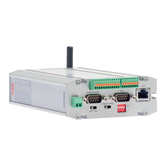
Section 2 1MRS758458 F ARR600 overview Physical interfaces 2.2.1 Front panel The I/O connector type on the front panel depends on the device type. Table 1: Available I/O connector types Device type Connector ARR600A3261NA Digital connector IO-1 ARR600A3262NA Digital and analog connector IO-2... - Page 17 Section 2 1MRS758458 F ARR600 overview GUID-50B15E54-D86B-4361-B9B8-9BD5AFAA66C7 V2 EN-US Figure 2: Front panel with IO-2 1 Power supply 12...48 VDC 2 IO-2 digital and analog I/O connector (only in certain product models) 3 LAN/WAN port 4 Console/application serial port 5 Power switch...
-
Page 18: Back Panel
Section 2 1MRS758458 F ARR600 overview GUID-54FB05F6-B156-4CF5-8E22-F9A5BC2E7E0C V1 EN-US Figure 3: Power supply connector Pin 1 Positive (+) Pin 2 Negative (-) The unit is protected against reversed polarity in specified voltage range. Power switch The power switch enables or disables the operation of the device. -
Page 19: Side Panel
Section 2 1MRS758458 F ARR600 overview 2.2.3 Side panel The ten LEDs on the side panel of the device indicate the status of the device. Only five of them are connected. The LEDs are numbered 1...10 starting from the rear panel side. -
Page 20: Product Information Label
Ethernet MAC address. Firmware version The device's firmware version is visible on the welcome page (System/Welcome Page), which is displayed after logging in to the device. For firmware updates, contact ABB's technical customer support. ARR600 User Manual... -
Page 21: Section 3 Physical Connections
The baud rate is fixed to 115200 bps when the port is configured in the serial console mode. GUID-9F6668AA-EBAB-46B5-A1AF-35D8AE3E6C12 V1 EN-US Figure 6: Console/RS1 port connector Table 3: Console/RS1 port pinout Function Table continues on next page ARR600 User Manual... -
Page 22: Serial Port 2
No flow control 3.1.1.2 Serial port 2 Serial port 2 can be configured to multiple serial formats (RS-232/422/485). The default is RS-232. GUID-9F6668AA-EBAB-46B5-A1AF-35D8AE3E6C12 V1 EN-US Figure 7: Application serial port Table 5: Application serial port pinout (RS-232) Function ARR600 User Manual... - Page 23 RS-232 mode. This could damage the port and the connected equipment. Table 8: Application serial port pinouts in RS-422/485 modes RS-422 full-duplex (4-wire) RS-485 half-duplex (2-wire) RXD positive (in) TXD negative (out) TXD/RXD negative (out/in) Table continues on next page ARR600 User Manual...
-
Page 24: Ethernet
GPRS, 3G or LTE frequency bands. The antenna is connected directly to the connector located on the device's back panel. Commercially available antennas are usually provided with a flexible 50 Ω cable with a length of 2...3 meters and a male type SMA connector. ARR600 User Manual... - Page 25 Section 3 1MRS758458 F Physical connections If the PIN code query is enabled, check that the ARR600 configurator has the correct PIN code entered in the wireless WAN submenu. ARR600 User Manual...
-
Page 27: Section 4 Getting Started
Example: Laptop IP is 10.10.10.11 with netmask 255.255.255.0. Check the IP configuration with the ping command in the command line. In a Web browser, connect to the device over the HTTPS protocol using the device’s IP address. ARR600 User Manual... -
Page 28: User Interface
"WAN", the firewall configuration needs to allow Web UI and SSH access from WAN (Firewall/General and enable both Allow WebUI access from WAN and Allow SSH access from WAN). The VLAN functional mode of the Ethernet port requires an external VLAN switch. ARR600 User Manual... -
Page 29: Configuring Mobile Wan
WAN, set Interface to Mobile WAN or Ethernet WAN, whichever is not selected as the default gateway. If the primary WAN interface comes down, the device automatically switches the default route to the backup WAN interface. Click Submit to save the settings. Restart the device. ARR600 User Manual... -
Page 31: Section 5 Network Configuration
WAN switch logic to try the secondary interface. 5.2.3 Configuring the mobile WAN interface Set Enable to Yes. If the SIM card is protected by a PIN code, enter the code in the PIN Code field. ARR600 User Manual... -
Page 32: Setting Wan Failover And Backup Routing
If the backup WAN interface needs to come up only when the primary interface goes down, select Yes. • If both the wireless and Ethernet WAN interfaces have to be up all the time, select No. Click Submit to save the settings. Restart the device. ARR600 User Manual... -
Page 33: Routing Parameters
This setting defines Host how the routing is configured with Default route OpenVPN. See OpenVPN application note. Configuring the network monitor The network monitor detects Internet connectivity drops by sending ping packets to designated targets. Its use is recommended. ARR600 User Manual... -
Page 34: Configuring Dns Proxy
In the left pane, under System, click Status to view network status information. In the left pane, under Tools, click Modem Info to view the status of the wireless modem. Check if the cellular LED is flashing, indicating network traffic. ARR600 User Manual... -
Page 35: Section 6 Serial Port Configuration
To modify an existing RTU configuration, click Edit picture on the right. • To change the current RTU application configuration, select a configuration from the Active configuration drop-down menu and click Set. Reboot the device to activate the selected settings. ARR600 User Manual... - Page 36 Section 6 1MRS758458 F Serial port configuration See the Wireless I/O Gateway ARR600 RTU configuration guide Technical Note for more information on RTU application parameters. ARR600 User Manual...
-
Page 37: Section 7 Additional System Configuration
In the “Manual” mode, enter the time and date in the Time and Date fields, respectively. Clicking Copy PC changes the device’s time and date settings to match the connected PC. This requires JavaScript support from the browser. Click Submit to save the settings. ARR600 User Manual... -
Page 38: Restoring Factory Default Settings
Selecting Last Boot allows saving the configuration in use when the device was booted the previous time. Type a name for the profile. Click Submit to save the profile. It is possible to clone, export, and import profiles in the same view. ARR600 User Manual... -
Page 39: Section 8 Service Configuration
Selects which SSH protocol versions are enabled in SSH SSH1, SSH2 version Server. It is recommended to allow only SSH protocol version 2 (SSH2) to be used. SSH public SSH Public keys can be added for remote logins with SSHkeys. keys ARR600 User Manual... - Page 40 Selects the supported dyndns service provider service provider DynDNS client Defines how often (in seconds) the device's IP is checked update interval DynDNS Arctic name reported to service, for example, host name hostname Table continues on next page ARR600 User Manual...
- Page 41 SSH private key to be used if the SSH connection protocol is identity selected. SSH public SSH public key to be used if the SSH connection protocol is selected. This key can be copied to Patrol server. Table continues on next page ARR600 User Manual...
- Page 42 Allow remote Enables remote management by Patrol server No, Yes management Allow LAN Allows periodical local network scan for ABB devices. Currently, No, Yes device scan the supported device is RIO600. ARR600 User Manual...
-
Page 43: Section 9 Iec-104 Application Settings
1200, 2400, 4800, 9600, 19200, 38400, 57600 Data bits Number of data bits used on IEC-101 serial communication 5, 6, 7, 8 Parity Parity method used on IEC-101 serial communication None, Even, Table continues on next page ARR600 User Manual... - Page 44 IEC-101 link. The t1 must be longer than the network round-trip-time. The IEC-104 standard suggests 15 seconds. Table continues on next page ARR600 User Manual...
- Page 45 Reply header Defines the timeout in milliseconds that the device waits the 1...65000 timeout reply to start from IEC-101 slave after command or request. Table continues on next page ARR600 User Manual...
- Page 46 0.1 second increments for packet collector. If there has been data on packet collector over MAX TIME, the data is sent to network. The value must be smaller than t1. Table continues on next page ARR600 User Manual...
- Page 47 Other settings Write syslog Write syslog defines if the error messages are stored to system No, Yes log file or not. The system log is available by using Web user interface. ARR600 User Manual...
-
Page 49: Section 10 Modbus Application Settings
Modbus ASCII over TCP and Modbus ASCII over UDP network protocols • Generates and filters out gateway exceptions • Makes automatic connection management • Enables multiple server sessions over the network • Offers unlimited amount of masters on the network side ARR600 User Manual... -
Page 50: Modbus Mode
If the slave does not reply during defined timeout or if the reply is corrupted, the device sends “gateway exception message” back to the master if the exception generation is enabled. Otherwise, the reply is returned. Multiple masters can connect simultaneously to the Gateway, which handles the multiplexing between masters. ARR600 User Manual... -
Page 51: Configuring The Network Master To Serial Slaves Mode
“Even”, an even parity bit is generated and inspected. If set to “Odd”, odd parity bits are generated and inspected. Stop bits Defines the number of stop bits used in Modbus serial 1, 2 communication. Table continues on next page ARR600 User Manual... - Page 52 Pass gateway If set to “Yes”, gateway exception replies from the slave side are No, Yes exceptions passed to the master. If set to “No”, the replies are filtered away. Network server settings Table continues on next page ARR600 User Manual...
-
Page 53: Modbus Register Maps
Modicon notation Properties 1 (0x01) Read Coils 0…3 00001…00004 Read digital outputs 2 (0x02) Read Discrete 0…5 10001…10006 Read digital inputs Inputs 3 (0x03) Read Multiple 0…5 40001…40006 Read input counters Holding Registers Table continues on next page ARR600 User Manual... - Page 54 0…3 00001…00004 Write digital output 6 (0x06) Write Single 0…5 40001…40006 Clear input counter Holding Register 15 (0x0F) Write Multiple Coils 0…3 00001…00004 Write digital outputs 16 (0x10) Write Multiple 0…5 40001…40006 Clear input counters Holding Registers ARR600 User Manual...
-
Page 55: Section 11 I/O Interface
Table 21: I/O connector pins for IO-1 (8DI+2DO) Symbol Description Vcc out DI_1 Digital input, 5...60 V DI_2 Digital input, 5...60 V DI_3 Digital input, 5...60 V DI_4 Digital input, 5...60 V Table continues on next page ARR600 User Manual... -
Page 56: Digital Input (Io-1)
IN_COMMON Digital input common pin 11.1.2 Digital output (IO-1) The digital output of the device is optically isolated and can be used for controlling low current external devices. The output is a CMOS relay which is protected by a ARR600 User Manual... -
Page 57: Digital And Analog Connector Io-2 Pins
OUT_B Digital output B pin 11.2 Digital and analog connector IO-2 pins GUID-37D5163F-322B-4D9F-908D-5493C81E8F8A V3 EN-US Figure 13: I/O connector pin numbering for IO-2 1 DIO pin 1 2 DIO pin 12 3 AIO pin 1 4 AIO pin 8 ARR600 User Manual... -
Page 58: Digital Input (Io-2)
The inputs are optically isolated and work with voltage (bipolar) levels from 5 to 60 V. This range is guaranteed to be interpreted as a logical high state. Voltage levels less than 1.65 V are interpreted as a logical low state. ARR600 User Manual... -
Page 59: Digital Output (Io-2)
The input voltage to the power supply connector is circulated back to the I/O connector of the device. This DC output can be used, for example, together with digital outputs in order to simplify external circuitry and wiring. ARR600 User Manual... -
Page 61: Section 12 Troubleshooting
With these settings, the Internet should be accessible on the laptop. 12.2 Viewing the system log In the left pane, under Tools, select System Log. If necessary, refresh the system log with the Web browser’s reload or refresh button. ARR600 User Manual... -
Page 63: Section 13 Technical Data
Protection class IP30 Table 27: Supported protocols Master protocol Slave protocol IEC 60870-5-104 IEC 60870-5-101 IEC 60870-5-104 Modbus RTU/ASCII, Modbus TCP Modbus TCP Modbus RTU/ASCII TCP/IP, UDP/IP (DNP3) Serial gateway - serial port data stream (such as DNP3) ARR600 User Manual... - Page 64 IEC 60870-5-101 protocol support Full serial and modem signals 300...460 800 bps Data bits: 7 or 8 Stop bits: 1 or 2 Parity: None, Even, Odd Flow control: None, RTS/CTS Protection: 15 kV ESD and short circuit ARR600 User Manual...
- Page 65 (EFT) EN 61000-4-4 (2012-04) Surge EN 61000-4-5 (2005-11) Conducted radiofrequency electromagnetic field EN 61000-4-6 (2008-10) Power frequency magnetic field EN 61000-4-8 (2009-09) Table 31: RoHS and REACH compliancy Description Reference Directive RoHS directive 2002/95/EC REACH directive 2006/1907/EC ARR600 User Manual...
-
Page 67: Section 14 Glossary
1979. Originally used for communication in PLCs and RTU devices. Modbus ASCII Link mode using 7-bit ASCII characters Modbus RTU Link mode using 8-bit binary characters Network time protocol Password authentication protocol Random access memory Ring Indicator RISC Reduced Instruction Set Computer ARR600 User Manual... - Page 68 Supervision, control and data acquisition Subscriber identity module SNMP Simple Network Management Protocol SNTP Simple Network Time Protocol Transmission Control Protocol TCP/IP Transmission Control Protocol/Internet Protocol Transmit exchange data User datagram protocol Virtual Private Network Wide area network ARR600 User Manual...
- Page 72 — ABB Distribution Solutions Digital Substation Products P.O. Box 699 FI-65101 VAASA, Finland Phone +358 10 22 11 abb.com/mediumvoltage © Copyright 2021 ABB. All rights reserved.