Table of Contents
Advertisement
Quick Links
Advertisement
Table of Contents

Related Manuals for ABB Welcome IP


Summary of Contents for ABB Welcome IP
- Page 1 System Manual │ 08.04.2019 ABB-Welcome IP...
-
Page 2: Table Of Contents
Planning the system and the installation ..................5 Design lines ............................ 5 Basic principles ..........................5 Overview of product range ......................... 6 Calculation of consumption of a ABB-Welcome IP system ............. 6 Selection of the correct PoE (commercially available) ..............7 Device overview ..........................8 2.3.1 Outdoor stations .......................... - Page 3 Joining device together ......................... 53 4.6.1 Linking devices in the management software ................53 Information about planning and application ....................54 Adressing ABB-Welcome IP (devices networking/connecting) ............. 54 Network / Data transmission ......................56 5.2.1 Ethernet cable / Ethernet network ....................56 ®...
-
Page 4: Overview
In contrast to the analogue ABB-Welcome devices they do not require their own interconnected cabling. Depending on the equipment of the building the ABB-Welcome IP devices for the exchange of information and the power supply share the LAN network cables with other systems. These run parallel. -
Page 5: Information On The Manual
Overview Information on the manual This manual describes the ABB-Welcome IP system. It supports you in the selection and planning of the correct structure. It contains an overview of currently available components and provides ideas for practical combination and integration. -
Page 6: Overview Of Product Range
Overview of product range Overview of product range Calculation of consumption of a ABB-Welcome IP system Power supply: Power supply: Recording of Device Consumption power (W) PoE switch Local IP touch 7" ● ● 300 mA / 27 VDC IP touch 5"... -
Page 7: Selection Of The Correct Poe (Commercially Available)
■ The minimum band width amounts to 100 Mbps. ■ ABB-Welcome IP devices must be operated with a PoE switch that meets standard 802.3af. ■ – During selection observe that the absolute output on the PoE switch is adequate for all devices to be connected. -
Page 8: Device Overview
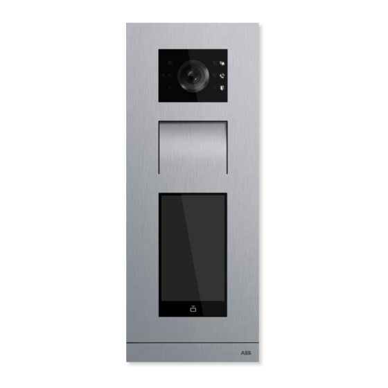
Overview of product range Device overview 2.3.1 Outdoor stations ABB-Welcome IP Outdoor stations are installed in the outdoor and indoor areas. The versatility of the devices makes them suitable for the following areas: Building entrances ■ Perimeter areas ■ Storey areas ■... - Page 9 Overview of product range Article Number H8138.T-. H8138.K-. H81381P.-. IP touch 5" IP keypad outdoor IP pushbutton Type outdoor station station outdoor station Video image 720P 720P 720P Camera angle 130° 130° 130° Anti-mist camera ● ● ● Automatic day/night switchover ●...
-
Page 10: Ip Touch 7" And Guard Unit
Overview of product range 2.3.2 IP touch 7" and Guard unit The door call is signalled at the IP touch 7" or Guard unit. Here the call is received and the door is opened when a visitor arrives. The camera image is displayed directly, to ensure that you immediately see who is at the door and you can communicate with the visitor. - Page 11 Overview of product range Article number H82364 H82365 H82366 H8303 Type IP touch 7" IP touch 7" IP touch 7" Guard unit Touch screen ● ● ● ● Extension on app without additional system equipment (prerequisite is ● ● ● ―...
-
Page 12: System Devices
Overview of product range 2.3.3 System devices Fig. 3: System devices System Manual 2CKA000073B9795 │12... - Page 13 Overview of the versions of the system controller Smart Access Point PC version * Smart Access Point Smart Access Point (Management Lite software) D04012 D04011 (see note) Control ABB-Welcome IP ● ● ● (Door communication) Control Busch- VideoControl (Video ● ● ―...
- Page 14 Overview of product range [3] Power supply YSM01-PS The „Power supply“ supplies the power for system devices in the following cases: No power is supplied via the network. ■ The number of system devices is high to the extent that the power supply via the network is ■...
-
Page 15: Mounting Accessories
Overview of product range Mounting accessories 2.4.1 Overview Overview of functions mounting boxes The mounting boxes for surface mounting or flush-mounted installation are available separately in the corresponding size for each device. The product is packed with accessories to guarantee a high-quality installation. Note Mounting boxes for surface mounting or flush-mounted installation must be ■... - Page 16 Overview of product range Fig. 4: Mounting boxes / Mounting box accessories Surface mounting Mounting boxes for surface mounting Surface mounting box for indoor station „IP touch 7"“ ■ Surface mounting box for outdoor stations size 1/3, size 1/4, size 1/5, size 2/3 ■...
- Page 17 Overview of product range Sizes for the outdoor station mounting boxes Outdoor station Size 1 x 5 1 x 4 Outdoor station Size 1 x 3 2 x 3 System Manual 2CKA000073B9795 │17...
-
Page 18: Mounting Boxes For Flush-Mounted Installation
Overview of product range 2.4.2 Mounting boxes for flush-mounted installation Mounting boxes for flush-mounted installation: Outdoor station 1 x 5 1 x 4 1 x 3 2 x 3 41385.F-xxx / 41384.F-xxx / 41383.F-xxx / 41386.F-xxx / 41385.PB-xxx 41384.PB-xxx 41383.PB-xxx 41386.PB-xxx Mounting boxes for flush-mounted installation: Indoor station 42363.F-xxx... -
Page 19: Mounting Boxes For Surface Mounting
Overview of product range 2.4.3 Mounting boxes for surface mounting Mounting boxes for surface-mounted installation: Outdoor station 1 x 5 1 x 4 1 x 3 2 x 3 41385.S-xxx 41384.S-xxx 41383.S-xxx 41386.S-xxx Mounting boxes for surface-mounted installation: Indoor station 42363.S-xxx System Manual 2CKA000073B9795 │19... -
Page 20: Support Bases For Mounting On Desktop
Overview of product range 2.4.4 Support bases for mounting on desktop Support base: Indoor stationIP touch 7" 42363.S-xxx Support base: Guard unit The Guard unit has been designed exclusively for mounting on desktops. No additional accessories are required for mounting on the desktop. System Manual 2CKA000073B9795 │20... -
Page 21: Mounting Possibilities
Overview of product range 2.4.5 Mounting possibilities 2.4.6 Mounting in hollow walls Cut a hole according to the size of the outdoor station used into the facade. The suitable template is enclosed with the box. Dimensional drawings, . Note The encircling "collar" of the flush- mounted box must rest on the facade! Fig. -
Page 22: Mounting In Clinker Facades
Overview of product range 2.4.7 Mounting in clinker facades Chisel a hole according to the size of the outdoor station used into the facade provided. The suitable template is enclosed with the box. Dimensional drawings, . The installation depth of the box is 40 mm. Note The encircling "collar"... - Page 23 Overview of product range Note Ensure that the installation height of the device carrier and the flush-mounted box matches the thickness of the planned exterior insulation (e.g. 160 mm exterior insulation). Fig. 9: Mounting height of the device carrier and the flush-mounted box 2.
-
Page 24: Mounting With Stiff Lan Cables
Overview of product range 2.4.9 Mounting with stiff LAN cables Cat. 6 cables (and higher) a very stiff and thick. To handle the partly tight flush-mounted boxes with these cables can be a problem. A proven solution has been to use a flat LAN cable for the last short piece in front of the device and fit it to the actual LAN cable with a universal LAN module (e.g. -
Page 25: Connection / Connecting Diagram
This section informs about prerequisites and procedures for the installation and mounting of selected system components. Prerequisites The prerequisites for the installation of the ABB-Welcome IP system are listed in the following: Network Own physical network or VLAN with Quality of Service (QoS). -
Page 26: Installation / Data Transmission
Overview of product range Installation / Data transmission Information about basic functions and principles of operation of the components for data transmission is available at Chapter 5 “Information about planning and application“ on page 54. System Manual 2CKA000073B9795 │26... -
Page 27: Device Functions
If you are not home at present, the visitor can leave you a message. The ABB-Welcome App turns your smartphone or tablet into a virtual indoor station while you are travelling. As is normal, you are informed about all visitors, talk to them and open the door for them. - Page 28 Otherwise the replay of images may not be able to be carried out. – ABB is not liable for the performance of an SDHC card. Audio files can be used in .mp3 and *.wav format as door call tone.
- Page 29 Device Functions Remote access via ABB-Welcome App You do not miss a visitor also when you are not at home. With the ABB-Welcome App for iOS and Android you have an indoor station always with you. Integration into building automation The system can be smoothly integrated into automation systems such as free@home or KNX.
-
Page 30: Commissioning
Section 1 Preparing devices and assigning the physical addresses. (Detailed information on the system of the addresses, see chapter 5.1 “Adressing ABB-Welcome IP (devices networking/connecting)“ on page 54) There are two ways for assigning the addresses. - Page 31 IP address 10.0.0.1. – After the login select the mode: "Residential". see chapter 4.5.1 “Project import from ABB-Welcome App“ on page – The later IP address of system controller "Smart Access Point" must be determined on a router.
- Page 32 Commissioning Section 3 Joining the device together The devices are joined in the management software of the "Smart Access Point" system controller. – Call up the system controller again via the browser of the PC if there is no longer a connection. Joining the device together.
-
Page 33: Physical Addresses - Preparing And Addressing Devices Manually
Commissioning Physical addresses ― Preparing and addressing devices manually If the devices have a display, the addressing is carried out on the device itself. If the devices do not have a display, the addressing is carried out via the indoor station. 4.2.1 Physical addresses ―... -
Page 34: Ip Touch 7" And Guard Unit
Commissioning 4.2.2 IP touch 7" and Guard unit For commissioning you are located in: Section 1 (Preparing the devices) Overview of commissioning: see chapter 4.1 “Overview of commissioning“ on page 30 First address stations IP touch 7" or Guard unit. Addressing is carried out in the same way for all versions. -
Page 35: Outdoor Station Without Display
Commissioning 4.2.3 Outdoor station without display For commissioning you are located in: Section 1 (Preparing the devices) Overview of commissioning: see chapter 4.1 “Overview of commissioning“ on page 30 The LEDs light up permanently during the automatic boot up. Fig. 17: Outdoor station without display: Engineering mode To address the device, perform the following steps: 1. - Page 36 Commissioning 3. Switch to the engineering menu at the indoor station. – Start function "Outdoor station settings". – The outdoor station is searched for automatically. – Address the outdoor station and save the entries. 4. Restart the outdoor station. The outdoor station is addressed. System Manual 2CKA000073B9795 │36...
-
Page 37: Outdoor Station With Display
Commissioning 4.2.4 Outdoor station with display For commissioning you are located in: Section 1 (Preparing the devices) Overview of commissioning: see chapter 4.1 “Overview of commissioning“ on page 30 Fig. 19: Outdoor station with display: Engineering settings To address the device, perform the following steps: 1. - Page 38 Commissioning Note The engineering password must be changed the first time you access the engineering settings. – The basic setting is 345678. – This password should only be used for the first setup and changed to a different password. It cannot be used as actual password. Note If a wrong engineering password is entered 10 times within 5 minutes, no further tries are possible for the next 5 minutes.
-
Page 39: Ip Actuator
Commissioning 4.2.5 IP actuator For commissioning you are located in: Section 1 (Preparing the devices) Overview of commissioning: see chapter 4.1 “Overview of commissioning“ on page 30 Fig. 20: IP actuator: Engineering mode To address the device, perform the following steps: 1. - Page 40 Commissioning 3. Switch to the technical menu at the indoor station. – Start function "IP actuator settings". – The IP actuator is searched for automatically. – Address the IP actuator and save the entries. 4. Restart the IP actuator. The IP actuator is addressed. System Manual 2CKA000073B9795 │40...
-
Page 41: Physical Addresses - Preparing And Addressing Devices Viaabb-Welcome App
On the rear side of each device are 2 stickers with the serial numbers of the device. One of them is fitted with a QR code. This is necessary for the preparation of the device with the ABB- Welcome App. - Page 42 Start creation of the building structure 2. Add a building structure the ABB-Welcome App, if this has not yet been created. 3. In the ABB-Welcome App in the building structure switch into the room to which the device is to be added.
- Page 43 5. On the rear side of the device scan the QR code on the sticker with the serial number. – The information of the device is stored in the project in the ABB-Welcome App. This information is transferred in a later step into the " Smart Access Point" for the commissioning process.
-
Page 44: Adding Devices - Preparation
Commissioning Adding devices - Preparation 4.4.1 Connecting a PC with the "Smart Access Point" system controller For commissioning you are located in: Section 2 (Adding devices in the system) – Section A: (Connecting system controller with a PC) Overview of commissioning: see chapter 4.1 “Overview of commissioning“... - Page 45 Commissioning Use the following steps to connect with the PC: Fig. 26: System controller "Smart Access Point" in network list of the PC 1. Connect the PC with the WLAN of system controller "Smart Access Point". – The WLAN access data are located on the device. –...
-
Page 46: Adjusting Ip Address To A Pc
Commissioning 4.4.2 Adjusting IP address to a PC For commissioning you are located in: Section 2 (Adding devices in the system) – Section A: (Connecting system controller with a PC) Overview of commissioning: see chapter 4.1 “Overview of commissioning“ on page 30 The IP address of the connection must be put on the same area on the PC / laptop as that of the device (only required once). - Page 47 Commissioning Setting of the IP address according to the example of Windows 10 operating system. Use the following steps to set the IP address: 1. Switch to the system controller. 2. Open: The network and the enabling centre [1]. 3. Open: Connections [2]. –...
-
Page 48: Determining The Ip Address Via Router
Commissioning 4.4.3 Determining the IP address via router For commissioning you are located in: Section 2 (Adding devices in the system) – Section A: (Connecting system controller with a PC) Overview of commissioning: see chapter 4.1 “Overview of commissioning“ on page 30 Fig. -
Page 49: Adding Devices
Two modes are available for the connection. One mode must be selected during the course of the steps. "Residential" mode: – The ABB-Welcome App must be connected with the same router as the system controller "Smart Access Point". – In this case the ABB-Welcome App locates the available system controller "Smart Access Point"automatically. - Page 50 Commissioning Fig. 31: App: Project export 3. Select the desired project on the smartphone and upload it into system controller "Smart Access Point". Fig. 32: System controller: Project selection for project import 4. On system controller "Smart Access Point" select the project to which the devices are to be added, and confirm the project.
-
Page 51: Add Manually
Commissioning 4.5.2 Add manually For commissioning you are located in: Setion 2 (Adding devices in the system) – Section B: (Adding devices) Overview of commissioning: see chapter 4.1 “Overview of commissioning“ on page 30 Fig. 33: Main menu: Device Management Use the following steps to add devices manually: 1. -
Page 52: Adding Via Automatic Search
Commissioning 4.5.3 Adding via automatic search For commissioning you are located in: Setion 2 (Adding devices in the system) – Section B: (Adding devices) Overview of commissioning: see chapter 4.1 “Overview of commissioning“ on page 30 Fig. 34: Main menu: Start search Use the following steps to search for devices automatically: 1. -
Page 53: Joining Device Together
Commissioning Joining device together 4.6.1 Linking devices in the management software For commissioning you are located in: Section 3 (Joining device together) Overview of commissioning: see chapter 4.1 “Overview of commissioning“ on page 30 Outdoor stations, indoor station and the IP actuators must be joined to each other. This is important for the door opener. -
Page 54: Information About Planning And Application
Information about planning and application Information about planning and application Adressing ABB-Welcome IP (devices networking/connecting) Fig. 36: Principle of addressing Buildings Floors Apartment Device in an apartment The address of a device is principally the same for all devices. The address consists of 4 parts. - Page 55 Information about planning and application Building Floor Apartment Device Address Address Address Address Indoor station 1 ... 999 01 ... 63 01 ... 32 01 ... 08 Public outdoor 000 … 999 ― ― 01 ... 64 station Private outdoor 1 ...
-
Page 56: Network / Data Transmission
It also defines different protocols for data transmission. Ethernet is possible both via twisted pair cable (copper cables) and also as OWG (glass fibre). The connection to ABB-Welcome IPdevices is made via twisted pair cables of category 5 or higher with RJ-45 plugs. -
Page 57: Integration Abb-Free@Home
Cat 5e cables would be sufficient for most applications. The ABB-Welcome IP devices are designed for connection with Cat 5e cables. Cat 5e is the globally most used installation cable. It makes transmission rates of up to 1,000 Mbits/s possible. -
Page 58: Poe Planning (Ethernet, Wlan)
Version 802.3at is the successor of 802.3af. It is downward compatible to 802.3af, i.e. all 802.3at PSE devices can also supply power to 802.3af PD devices. For operating ABB- Welcome IP devices the performance of 802.3af is already fully adequate. - Page 59 However, it should be noted that a Cat 5e cable exhibits a higher generation of heat due to its low cable cross section. This can, among others, have a negative effect on the reachable transmission range. Compatibility (with foreign devices) The ABB-Welcome IP devices are exclusively compatible with standardised PoE versions. System Manual 2CKA000073B9795 │59...
-
Page 60: Function Test
Information about planning and application Function test Electric connection If the device starts, the power supply is guaranteed. If the device does not start: For the supply via PoE, ensure that both interfaces support PoE. Individual devices or extension modules can not be supplied by PoE. For the supply via auxiliary power supply, ensure that the auxiliary power supply is supplied with power and both devices are correctly interconnected. -
Page 61: It Protection
5.4.3 Foreign control of your house If a third-party succeeds in hacking himself into a ABB-Welcome IP system, there is the risk of foreign control and reprogramming. This would result in the loss of a large part of the added value of the electrical installer and the system may have to be reprogrammed. -
Page 62: Minimisation Of The Risks
Information about planning and application Anti-theft devices Anti-theft devices should be used (protection with screws, only removable with a tool, high resistive forces against removal). Device password Use a password if it is supported by the device. A password prevents unauthorised access to the device. -
Page 63: Password Manager
For the remote access a VPN tunnel or the Living Space Portal MyBuildings is recommended. The portal MyBuildings is a service of ABB which guarantees the utmost operating comfort for remote access with smartphone and tablet. The end customer does not need a DynDNS account. -
Page 64: Case Studies
Case studies Case studies Legend Legends in the graphics: Outdoor station: Mini video outdoor station H8131xPx-A Outdoor station: H8138.T-. IP touch 5" outdoor station System controller: Smart Access Point D0401. Indoor station: IP touch 7" H8236.-. Indoor station: Guard unit H8303 Auxiliary power supply: Power supply YSM01-PS IP actuator: H8304 IP actuator Lift control: Lift control module YSM23-LC... -
Page 65: Private Apartment
Case studies Private apartment In the following examples different situations of simple installations in apartments are illustrated. The main purpose of the examples is to become familiar with the topics. Apartment (Switch with PoE and Routing): The PoE switch and routing are enabled in the apartment. That is why no additional devices are necessary for this function. - Page 66 Case studies Apartment (Switch without PoE): The switch is not PoE-capable in the apartment. That is why an additional power supply is required. The indoor station in the version is intended for LAN connection. Fig. 39: Overview: Apartment (Switch without PoE) 100 - 240 V Fig.
- Page 67 Case studies Apartment (Switch without Routing): The switch is not routing-capable in the apartment. That is why an additional router is required. The indoor station in the version is intended for LAN connection. Fig. 41: Overview: Apartment (Switch without routing) Fig.
- Page 68 Case studies Apartment (no switch / router no PoE): No switch is available in the apartment. The connection is made via a router. The router is not PoE-capable. That is why an additional power supply is required. The indoor station in the version is intended for LAN connection. Fig.
- Page 69 Case studies Apartment (indoor station with WLAN): The PoE switch and routing are enabled in the apartment. That is why no additional devices are necessary for this function. The indoor station in the version is intended for WLAN connection. This, for example, makes a later extension possible for access control for inputs.
- Page 70 Case studies Apartment (with actuator): The PoE switch and routing are enabled in the apartment. That is why no additional devices are necessary for this function. The indoor station in the version is intended for LAN connection. The entrance door is equipped only with an automatic door opener. That is why an IP actuator is required which accepts the digital opening command and switches the door opener.
-
Page 71: Multifamily House
Case studies Multifamily house An extended simple installation with several apartments are illustrated in the following. Multifamily house (Switch with PoE and Routing): In the multifamily house the switch is PoE- and routing-capable. That is why no additional devices are necessary for this function. The indoor station in the version is intended for LAN connection. - Page 72 Case studies Fig. 50: Connection: Multifamily house (Switch with PoE and Routing) System Manual 2CKA000073B9795 │72...
-
Page 73: Residential Building Construction Project
Residential building construction project with numerous apartments and separate safety lift Task: The door communication is to be carried out via ABB-Welcome IP in a large residential building construction project. The lifts are to be connected with it. A separate safety lift is to be controlled via an own ABB-Welcome IP system. - Page 74 Case studies Separate Safety-Lift Abb. 51: Residential building construction project with numerous apartments and separate safety lift System Manual 2CKA000073B9795 │74...
- Page 75 Case studies LIFT 01 LIFT 02 100 - 240 V Fig. 52: Connection: Apartments of the building System Manual 2CKA000073B9795 │75...
- Page 76 Case studies 100 - 240 V R e l a y O U T 9 - 1 6 R e l a y O U T 9 - 1 6 1 2 3 4 5 6 7 8 1 2 3 4 5 6 7 8 S t a t u s S t a t u s...
- Page 77 Case studies 100 - 240 V R e l a y O U T 9 - 1 6 1 2 3 4 5 6 7 8 S t a t u s P o w e r R e l a y O U T 1 - 8 100 - 240 V Fig.
-
Page 78: Glossary
Glossary Cloud memory The data is stored on an external server. – In the ABB-Welcome IP system on the server of Busch-Jaeger. DHCP Dynamic Host Configuration Protocol – In a network, every device requires its own address so as to able to be recognised in the network. -
Page 79: Notes
Notes Notes System Manual 2CKA000073B9795 │79... -
Page 80: Index
Joining device together ......31, 53 Addressing ........30, 33, 41, 54 Addressing devices manually ......30, 33 Addressing devices via ABB-Welcome App ..30, 41 Legend ............64 Adjusting IP address to a PC ......31, 46 Linking devices ..........53 Management software - Linking devices .... - Page 81 Preparing addressing ........33 Support bases for mounting on desktop ....20 Prerequisites ..........25 System devices ..........12 Private apartment ......... 65 Project import from the ABB-Welcome App ..31, 49 Target group ..........5 System Manual 2CKA000073B9795 │81...
- Page 82 Busch-Jaeger Elektro GmbH A member of the ABB Group PO box 58505 Lüdenscheid Freisenbergstraße 2 58513 Lüdenscheid www.BUSCH-JAEGER.com info.bje@de.abb.com Central sales service: Tel.: +49 2351 956-1600 Fax: +49 2351 956-1700 Copyright 2019 Busch-Jaeger Elektro GmbH © All rights reserved...