
Related Manuals for ABB OTM C Series


Summary of Contents for ABB OTM C Series
- Page 1 Motorized change-over and transfer switches OTM_C Installation and operating instructions 34OTM_C / 1SCC303002M0204...
-
Page 3: Table Of Contents
Contents Installation and operating instructions, OTM_C Contents Introduction ........................4 Use of symbols ..........................4 Explanations of abbreviations and terms ..................4 Product overview ......................5 Quick start ......................... 6 Operating the motorized change-over switch electrically; remote control ........6 3.1.1 Locking electrical operation......................6 Operating the motorized change-over switch manually;... -
Page 4: Introduction
Installation and operating instructions, OTM_C 1. Introduction 1. Introduction This manual describes the installation and the basic operation of the motorized change-over and transfer switches, types OTM_C. The instructive part is followed by a section on available accessories. 1.1 Use of symbols Hazardous voltage: warns about a situation where a hazardous voltage may cause physical injury to a person or damage to equipment. -
Page 5: Product Overview
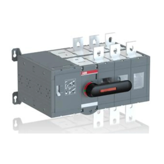
2. Product overview Installation and operating instructions, OTM_C 2. Product overview Motorized change-over switches (type OTM_C) are suitable for remote control. You can operate the motorized change-over switches either electrically by using the motor operator or manually by using the handle. -
Page 6: Quick Start
Installation and operating instructions, OTM_C 3. Quick start 3. Quick start This is a quick guide only meant for those who need a reminder of how to operate the unit. For more detailed instructions, see chapter 6. 3.1 Operating the motorized change-over switch electrically; remote control To operate the motorized change-over switch electrically: Remove the handle from the switch panel. -
Page 7: Operating The Motorized Change-Over Switch Manually; Local Operation
3. Quick start Installation and operating instructions, OTM_C 3.2 Operating the motorized change-over switch manually; local operation To operate the motorized change-over switch manually: Turn the Motor/Manual selector to the Manual (Man.) position to enable manual operation and to prevent electrical operation. Attach the handle to the switch panel. -
Page 8: Installation
Installation and operating instructions, OTM_C 4. Installation 4. Installation 4.1 Mounting the motorized change-over switch Use protection against direct contact. Figure 4.1 An example of using protection against direct contact 1SCC303002M0204, rev. D... - Page 9 4. Installation Installation and operating instructions, OTM_C Figure 4.2 Motorized change-over switches, drilling hole distances / screw-mounting, [mm/in] 1SCC303002M0204, rev. D...
-
Page 10: Dimensional Drawings
Installation and operating instructions, OTM160-2500_C 4. Installation 4.2 Dimensional drawings Figure 4.3 OTM160-250E_C_M Figure 4.4 OTM160-250E_WC_M 1SCC303002M0204, rev. D... - Page 11 4. Installation Installation and operating instructions, OTM160-2500_C Figure 4.5 OTM200U_C_M Figure 4.6 OTM315-400E_C_M 1SCC303002M0204, rev. D...
- Page 12 Installation and operating instructions, OTM160-2500_C 4. Installation Figure 4.7 OTM315-400E_WC_M Figure 4.8 OTM400U_C_M 1SCC303002M0204, rev. D...
- Page 13 4. Installation Installation and operating instructions, OTM160-2500_C Figure 4.9 OTM630-800E_C_M Figure 4.10 OTM600U_C_M 1SCC303002M0204, rev. D...
- Page 14 Installation and operating instructions, OTM160-2500_C 4. Installation Figure 4.11 OTM1000-1200E_C_M Figure 4.12 OTM1600E_C_M 1SCC303002M0204, rev. D...
- Page 15 4. Installation Installation and operating instructions, OTM160-2500_C Figure 4.13 OTM800-1200U_C_M Figure 4.14 OTM2000-2500E_C_M 1SCC303002M0204, rev. D...
- Page 16 Installation and operating instructions, OTM160-2500_C 4. Installation Figure 4.15 OTM1600U_C_M 1SCC303002M0204, rev. D...
-
Page 17: Mounting Positions
4. Installation Installation and operating instructions, OTM_C 4.3 Mounting positions The recommended mounting positions for motorized change-over switches are horizontal, wall mounted or table mounted. Figure 4.16 Mounting positions Do not install the motorized change-over switches in any other position than those described above. -
Page 18: Connecting
Installation and operating instructions, OTM_C 5. Connecting 5. Connecting Only an authorised electrician may perform the electrical installation and maintenance of motorized change-over switches. Do not attempt any installation or maintenance actions when a motorized change-over switch is connected to the electrical mains. Before starting work, make sure that the change-over switch is de-energised. -
Page 19: Operating
6. Operating Installation and operating instructions, OTM_C 6. Operating Never open any covers on the product. There may be dangerous external control voltages inside the motorized change-over switch even if the voltage is turned off. Never handle control cables when the voltage of the motorized change-over switch or external control circuits are connected. -
Page 20: Impulse Control
Installation and operating instructions, OTM_C 6. Operating Turn the Motor/Manual selection switch to the Motor (M) position, see Figure 6.2. Figure 6.2 Motor/Manual selection switch in the Motor (M) position Operate the motorized change-over switch with the push-buttons or selector switch via impulse control or continuous control. -
Page 21: Continuous Control
6. Operating Installation and operating instructions, OTM_C 6.1.2 Continuous control When using continuous control, the control command is supplied to the switch continuously. When you press the control button, the change-over switch is driven to the corresponding position (I, 0, II). Operation of position 0 will over-run control of the other positions;... -
Page 22: Manual Operation By Using The Handle
Installation and operating instructions, OTM_C 6. Operating 6.2 Manual operation by using the handle You can operate the motorized change-over switch manually by using the handle that is included in the delivery. To operate the motorized change-over switch manually: Turn the Motor/Manual selector to the Manual (Man.) position, see Figure 6.5. The motor operator is switched off and electrical operation is prevented. -
Page 23: Locking
6. Operating Installation and operating instructions, OTM_C 6.3 Locking You can lock the motorized change-over switch to a specific position. 6.3.1 Locking the electrical operation To disable electrical operation, lock the locking latch with a padlock. After the locking latch has been locked, the change-over switch cannot be operated electrically. - Page 24 Installation and operating instructions, OTM_C 6. Operating Figure 6.8 Locking the manual operation The handle cannot be removed when padlocked to position 0. The following chart shows the locking state information (the voltage on motor operator supply needed). Figure 6.9 Locking state information 1SCC303002M0204, rev.
-
Page 25: Technical Data
7. Technical data Installation and operating instructions, OTM_C 7. Technical data Motor operator, control circuit Value Cabling Rated operational voltage U [V] 220-240 Vac 50-60 Hz 110-125 Vac/dc 50-60 Hz 48 Vdc 24 Vdc Operating voltage range 0.85... 1.1 x U Operating angle 90°... - Page 26 Installation and operating instructions, OTM_C 7. Technical data Type Voltage Nominal Current Operating Operating OFF-time current Inrush time transfer when I-0, 0-I, time operating 0-II, II-0 I-II or II-I I-II or II-I OTM160...250_C 220-240 Vac 0,4 - 1,0 1,0 - 2,0 0,4 - 1,0 OTM160...250_C 110-125 Vac/dc...
-
Page 27: Accessories
8. Accessories Installation and operating instructions, OTM_C 8. Accessories 8.1 Terminal clamp sets Figure 8.1 Mounting of the terminal clamp sets, types OZXB_ and OZXA_ 1SCC303002M0204, rev. D... -
Page 28: Bridging Bars
Installation and operating instructions, OTM_C 8. Accessories 8.2 Bridging bars Figure 8.2 Mounting of the bridging bars (type OTZC_) to the motorized change-over switches OTM160-800E_C_ 1SCC303002M0204, rev. D... - Page 29 8. Accessories Installation and operating instructions, OTM_C Figure 8.3 Mounting of the bridging bars (type OTZC_) to the motorized change-over switches OTM1000-1600E_C_ and OTM800-1200U_C_ 1SCC303002M0204, rev. D...
- Page 30 Installation and operating instructions, OTM_C 8. Accessories Figure 8.4 Mounting of the bridging bars (type OTZC_) to the motorized change-over switches OTM2000-2500E_C_ and OTM1600U_C_ 1SCC303002M0204, rev. D...
-
Page 31: Terminal Shrouds
8. Accessories Installation and operating instructions, OTM_C 8.3 Terminal shrouds Figure 8.5 Mounting of the terminal shrouds (type OTS_ ) to the motorized change-over switches OTM160-800E_C_ 1SCC303002M0204, rev. D... - Page 32 Installation and operating instructions, OTM_C 8. Accessories Figure 8.6 Mounting of the terminal shrouds (type OTS_ ) to the motorized change-over switches OTM1000-1600E_C_ and OTM800-1200U_C_ 1SCC303002M0204, rev. D...
- Page 33 8. Accessories Installation and operating instructions, OTM_C Figure 8.7 Mounting of the terminal shrouds (type OTS_ ) to the motorized change-over switches OTM2000-2500_C_ and OTM1600U_C_ 1SCC303002M0204, rev. D...
-
Page 34: Auxiliary Contacts
Installation and operating instructions, OTM_C 8. Accessories 8.4 Auxiliary contacts Figure 8.8 Mounting of the auxiliary contacts, type OA_ 1SCC303002M0204, rev. D... -
Page 35: Voltage Sensing Connectors
8. Accessories Installation and operating instructions, OTM_C 8.5 Voltage sensing connectors Figure 8.9 Mounting of the voltage sensing connectors, type OMZB_ 1SCC303002M0204, rev. D... -
Page 36: Handle And Spare Fuse Storage
Installation and operating instructions, OTM_C 8. Accessories 8.6 Handle and spare fuse storage Figure 8.10 Handle and spare fuses can be stored on the motorized change-over switch by mounting the accessory OTVS_ . 1SCC303002M0204, rev. D... -
Page 37: Ul Standard Switches
9. UL standard switches Installation and operating instructions, OTM_C 9. UL standard switches Current Height Width Depth OTM200U_C 406 mm/16 in 305 mm/12 in 203 mm/8 in OTM400U_C 610 mm/24 in 356 mm/14 in 254 mm/10 in OTM600U_C 610 mm/24 in 700 mm/28 in 400 mm/16 in OTM800-1200U_C... -
Page 38: Phase Barriers
Installation and operating instructions, OTM_C 9. UL standard switches 9.1 Phase barriers Phase barriers or shrouds (see section 8.3) must be used to maintain a clearance of 1 inch on the motorized change-over switch types: OTM600U_C_, if the conductors are wider than 39 mm /1,54 in (phase barrier 68838), on OTM800-1200U_C_, if the lugs are wider than 54 mm /2,13 in (phase barrier 68912) and on OTM1600U_C_, if the lugs are wider than 100 mm / 3,94 in (phase barrier 68912). - Page 40 ABB Oy The technical data and dimensions are valid at the time of printing. We reserve the right to Low Voltage Switches subsequent alterations. P.O Box 622 FI-65101 VAASA, Finland Telephone +358 10 22 11 Telefax +358 10 22 45708...