
Related Manuals for ABB OTM C 21D


Summary of Contents for ABB OTM C 21D
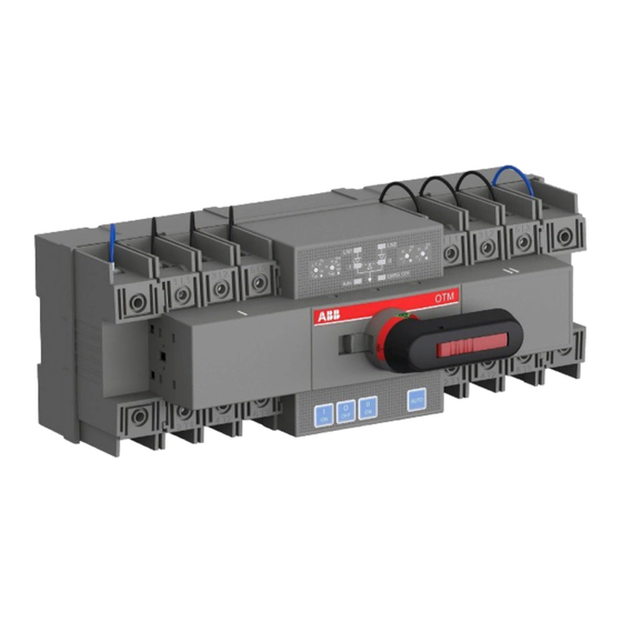
- Page 1 — I N S TA L L AT I O N A N D O P E R AT I N G I N S T R U C T I O N Automatic Transfer Switch OTM_C_21D...
-
Page 2: Table Of Contents
A U T O M AT I C T R A N S F E R S W I T C H , O T M _ C _ 2 1 D — Table of contents SYMBOLS & TERMS PRODUCT OVERVIEW QUICK START INTERFACE AND SETTINGS TECHNICAL DATA... -
Page 3: Symbols & Terms
A U TO M AT I C T R A N S F E R S W I TC H , OT M _ C _ 2 1 D — 1. Symbols & Terms — 1.1 Use of symbols Risk of Electric shock: warns about a situation where a hazardous voltage may cause phys- ical injury to a person or damage to equipment. -
Page 4: Product Overview
A U T O M AT I C T R A N S F E R S W I T C H , O T M _ C _ 2 1 D — 2. Product overview — 2.1 Product overview and packing The OTM_C21D automatic transfer switch can be operated handle, locally using push buttons or used as a source transfer switch in a three-phase... - Page 5 A U TO M AT I C T R A N S F E R S W I TC H , OT M _ C _ 2 1 D — 2.2 OTM_C21D switching sequence 2.2.1 Line 1 Priority (default mode) The transfer sequence of OTM_C21D can be sum- And the return sequence can be summarized in marized in following steps:...
- Page 6 A U T O M AT I C T R A N S F E R S W I T C H , O T M _ C _ 2 1 D 2.2.2 No line priority The transfer sequence of OTM_C21D can be sum- And the return sequence can be summarized in marized in following steps: the following steps:...
- Page 7 A U TO M AT I C T R A N S F E R S W I TC H , OT M _ C _ 2 1 D 2.2.3 Manual return mode The transfer sequence of OTM_C21D can be sum- And the return sequence can be summarized in marized in following steps: the following steps:...
-
Page 8: Quick Start
A U T O M AT I C T R A N S F E R S W I T C H , O T M _ C _ 2 1 D — 3. Quick start — 3.1 Operating the switch manually (local operation) To operate the switch manually: 1. - Page 9 A U TO M AT I C T R A N S F E R S W I TC H , OT M _ C _ 2 1 D — 3.2 Automatic operation OTM_C21D must be in automatic mode and the “AUTO”...
- Page 10 A U T O M AT I C T R A N S F E R S W I T C H , O T M _ C _ 2 1 D — 3.3 System testing 3.3.1 Local test 3.3.2 Remote test In automatic mode, “AUTO”...
- Page 11 A U TO M AT I C T R A N S F E R S W I TC H , OT M _ C _ 2 1 D — 3.4 Locking 3.4.1 Locking the electrical operation The switch can be padlocked in any position, causing that all operating modes and test operations are disabled, and handle cannot be inserted.
- Page 12 A U T O M AT I C T R A N S F E R S W I T C H , O T M _ C _ 2 1 D — 3.5 Modbus communication function OTM_C21D can achieve communication function by using the optional external Modbus RTU module.
- Page 13 A U TO M AT I C T R A N S F E R S W I TC H , OT M _ C _ 2 1 D 3.5.3 OTM_C21D registers information Information of registers, values and access is available in following table Register Address...
- Page 14 A U T O M AT I C T R A N S F E R S W I T C H , O T M _ C _ 2 1 D Register (continued) Address Function Values (DEC) code (DEC) MODBUS ADDRESS 03/06/16 1…32...
- Page 15 A U TO M AT I C T R A N S F E R S W I TC H , OT M _ C _ 2 1 D Register (continued) Address Function Values (DEC) code (DEC) LAST_ALARM 0=No alarms 1= Switch I transfer fail 2= Switch II transfer fail 3=Both I and II are ON...
- Page 16 ABB and its affiliates are not liable for damage and/or losses related to such security breaches, unauthorized access, interferen- ce, intrusion, leakage and/or theft of data or information.
-
Page 17: Interface And Settings
A U TO M AT I C T R A N S F E R S W I TC H , OT M _ C _ 2 1 D — 4. Interface and Settings — 4.1 Buttons Figure 11. Buttons Button Function Remarks... - Page 18 A U T O M AT I C T R A N S F E R S W I T C H , O T M _ C _ 2 1 D — 4.2 Leds Figure 12. LEDs Display Status description LN1/LN2 Source available Source available...
- Page 19 A U TO M AT I C T R A N S F E R S W I TC H , OT M _ C _ 2 1 D — 4.3 Rotary switch settings Transfer delay Ts The delay of transferring from the LN1 to the LN2 in automatic mode.
- Page 20 A U T O M AT I C T R A N S F E R S W I T C H , O T M _ C _ 2 1 D — 4.4 Dip switch setting The 9-bit dip switch is used to set the working modes of transfer switch.
- Page 21 A U TO M AT I C T R A N S F E R S W I TC H , OT M _ C _ 2 1 D — 4.5 Terminal outputs and inputs The switch has 11 bits of signal terminals for users to input and output signals.
-
Page 22: Technical Data
A U T O M AT I C T R A N S F E R S W I T C H , O T M _ C _ 2 1 D — 5. Technical data Automatic transfer switch Parameters Rated operational voltage Ue[V] Single-phase (2P) 220~240 V AC 50~60 Hz... -
Page 23: Installation
A U TO M AT I C T R A N S F E R S W I TC H , OT M _ C _ 2 1 D — 6. Installation — 6.1 Installation method The switch can be installed using screws or a DIN rail. - Page 24 A U T O M AT I C T R A N S F E R S W I T C H , O T M _ C _ 2 1 D The DIN rail installation mode is as follows: First pry out the latch with an appropriate tool, as shown in Fig.
- Page 25 A U TO M AT I C T R A N S F E R S W I TC H , OT M _ C _ 2 1 D — 6.2 Installation dimensions Figure 20. Dimensions...
-
Page 26: Optional Accessories
A U T O M AT I C T R A N S F E R S W I T C H , O T M _ C _ 2 1 D — 7. Optional accessories — 7.1 Bridging bars OTM32-125F2C21D OMZC03 OTM32-125F3C21D... - Page 27 A U TO M AT I C T R A N S F E R S W I TC H , OT M _ C _ 2 1 D — 7.2 Terminal shrouds OTS125T3 OTS125T1 OTS125T Figure 22. Terminal shrouds —...
- Page 28 A U T O M AT I C T R A N S F E R S W I T C H , O T M _ C _ 2 1 D — 7.4 Modbus communication module Figure 24. Modbus RTU communication module Do not break the box if Modbus RTU module is not ready for assembling When Modbus RTU is assembled to OTM_C21D, paste a cover to the hole to protect the switch from being polluted if the module needs to be removed...
-
Page 29: Maintenance And Common Troubleshooting
A U TO M AT I C T R A N S F E R S W I TC H , OT M _ C _ 2 1 D — 8. Maintenance and common troubleshooting — 8.1 Maintenance To ensure the operation reliability of switches, regular switching tests should be performed (once every 3 months) to confirm normal function. -
Page 30: Appendix
A U T O M AT I C T R A N S F E R S W I T C H , O T M _ C _ 2 1 D — 9. Appendix — 9.1 Wiring diagram Figure 25. Wiring diagram... - Page 31 A U TO M AT I C T R A N S F E R S W I TC H , OT M _ C _ 2 1 D • Read through this instruction book carefully before working on the switch, and keep this instruction book safe for later reference •...
- Page 32 — Contact us ABB Oy P.O. Box 622 FI-65101 Vaasa Finland abb.com/lowvoltage © Copyright 2021 ABB. All rights reserved. Specifications subject to change without notice.