
Related Manuals for ABB ZX0


Summary of Contents for ABB ZX0
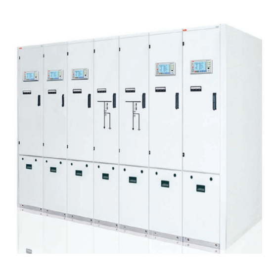
- Page 1 Manual for installation and operation HB 600/05 en ZX0 - block design Gas-insulated medium voltage switchgear...
-
Page 3: Handling
− With the aim of a smooth installation sequence and ensuring a high quality standard, have installation at site performed by specially trained personnel or managed and supervised by the ABB Service Department. − Ensure that installation, operation and maintenance are only performed by specialist electricians familiar with this manual. -
Page 4: Table Of Contents
Notes on earthing of a feeder panel or system section 4.1.2 Mechanism variants 4.1.2.1 Manual mechanism 1 4.1.2.1.1 Operation of the circuit-breaker 4.1.2.1.2 Operation of the three position disconnector 4.1.2.1.3 Emergency manual operation 4 | Manual ZX0 HB 600 en - Revision 05... - Page 5 Maintenance of the switching devices and their operating mechanisms Actions at the end of the service life 8 List of tools 9 Working materials, auxiliary materials and accessories Working materials Auxiliary materials Accessories 10 Technical data Manual ZX0 HB 600 en - Revision 05 | 5...
-
Page 6: Operation
Low-voltage electrical installations IEC 61936 Power installations exceeding 1 kV a.c. DIN EN 50110 Operation of electrical installations National technical accident prevention regulations e.g. for electrical systems and equipment and SF installations 6 | Manual ZX0 HB 600 en - Revision 05... -
Page 7: Commissioning
At a room height of at least 2400 mm and a short-circuit current ≤ 21 kA (only possible with wall installation), the length of the switchgear system must be at least 1600 mm. Manual ZX0 HB 600 en - Revision 05 | 7... - Page 8 You have chosen a gas-insulated switchgear of series ZX0 in block Please observe further documents in addition to this manual. The design. This switchgear from the ZX range is notable for the fol- documents relevant to your switchgear are part of the final docu- lowing features: mentation.
- Page 9 Cable termination compartment Sockets for capacitive voltage Cable connector indicator system High voltage cable Current transformer Cable clamp 1.13 Pressure relief disk Main earthing bar Pressure relief compartment Low voltage compartment Manual ZX0 HB 600 en - Revision 05 | 9...
-
Page 10: Despatch And Storage
(indoors or outdoors) can be found in the order documents. If the panel blocks are packaged, they are mounted on a pallet and secured to prevent them from slipping. 10 | Manual ZX0 HB 600 en - Revision 05... -
Page 11: Handling By Crane
Fig. 1.4.2.1: Crane handling of a block with width up to 1 m Fig. 1.4.2.2: Crane handling of a block with width of 1.2 m and more Manual ZX0 HB 600 en - Revision 05 | 11... -
Page 12: Handling By Hydraulic Lift Trolley
The high centre of gravity means there is a high risk of tipping. Avoid jerky motions! Fig. 1.4.3.1: Handling by hydraulic lift trolley 12 | Manual ZX0 HB 600 en - Revision 05... -
Page 13: General Site Requirements
Table 2.1.2.1: Tightening torques M 10 Nut on studbolt 12,5 Steel screw in pulling nut 18 - 24 Screw in inner cone socket Other screws of tensile class 8.8 Manual ZX0 HB 600 en - Revision 05 | 13... -
Page 14: General Information
Approx. 10 g of voltage transformers or blanking each part − Perform cleaning work immediately before assembly of the plugs for voltage transformer relevant component as follows: sockets 14 | Manual ZX0 HB 600 en - Revision 05... - Page 15 Fig. 2.1.3.2: Greasing the light, outer area of the blanking plug for the bus- voltage transformer sockets in the area between the arrows bar bushing in the area between the arrows Manual ZX0 HB 600 en - Revision 05 | 15...
- Page 16 No additional foundation frame is necessary. If no standard ABB foundation frames are used, observe the rel- evant construction and laying drawings for the special frames. The standard foundation frames are shown in figure 2.2.1.
- Page 17 - Install the following foundation frames in the same way. - Fasten the brackets (2) of the foundation frame to the Manual ZX0 HB 600 en - Revision 05 | 17...
- Page 18 When applying the floor topping, carefully fill under the foundation frame with topping material. Fig. 2.2.1.1: Installation of the floor frame Section A-A Top of finished floor Floor topping 18 | Manual ZX0 HB 600 en - Revision 05...
- Page 19 Fig. 2.3.1.1.1: Filling connector (1) with protective cap (2) in the low voltage Fig. 2.3.1.1.2: Filling connector (1) with valve pin (3) compartment Fig. 2.3.1.1.3: Filling connector with pressure gauge (5) and locking ring (4) Manual ZX0 HB 600 en - Revision 05 | 19...
- Page 20 (figure 2.3.1.3.3). Fig. 2.3.1.3.1: Fitting the guide pins using a threaded plate Fig. 2.3.1.3.3: Position of the guide pins in sectionalizer, riser and metering panels Fig. 2.3.1.3.2: Fitted guide pins 20 | Manual ZX0 HB 600 en - Revision 05...
- Page 21 Section A-A Panel floor (simplified) Coupler panel Riser panel Metering panel T-nut M 8 Washer 8,5 x 30 x 3 Feeder panel Dished washer Cheese head screw M 8 x 16 Floor frame Manual ZX0 HB 600 en - Revision 05 | 21...
- Page 22 Fig.. 2.3.2.1: Fastening the panel to the foundation frame Slot in the foundation frame section T-nut, M 8 Fastening of the panel to the foun- dation frame 22 | Manual ZX0 HB 600 en - Revision 05...
- Page 23 Fig. 2.3.2.2: Protective film for busbar sockets Fig. 2.3.2.4: Fitted contact tubes and silicone insulating parts Fig. 2.3.2.5: Positioning of the panel block to be erected Fig. 2.3.2.3: Inserting a contact tube Manual ZX0 HB 600 en - Revision 05 | 23...
- Page 24 Tool inside the low voltage compartment Fig. 2.3.2.7: Complete screw connections on the fastening brackets Fig. 2.3.2.9: Screwing the low voltage compartments together 24 | Manual ZX0 HB 600 en - Revision 05...
- Page 25 – sectional view M10 x 50 cheese head screw with washers and nut Tension clamp Blanking plug Busbar socket Thrust plate Fig. 2.3.3.1b: High dielectric strength blanking plugs in the busbar sock- Manual ZX0 HB 600 en - Revision 05 | 25...
- Page 26 Fasten the end cover at the locations provided (figure 2.3.4.2) us- ing screws. Finally, align the end cover. Fig.. 2.3.4.1: Fastening bracket for the end cover Fig. 2.3.4.2: Fastening points for the end cover 26 | Manual ZX0 HB 600 en - Revision 05...
- Page 27 − Start installation with the middle transformer. − Lay the transformer down, for example on the roof of the low voltage compartment. Fig. 2.3.5.1: Installed voltage transformer mcb: miniature circuit-breaker Manual ZX0 HB 600 en - Revision 05 | 27...
- Page 28 ● ● ● In a voltage transformer version with 2 windings plus tap or 2 windings plus e-n winding, "N" is implemented at the base plate of the voltage transformer. 28 | Manual ZX0 HB 600 en - Revision 05...
- Page 29 Releasing the earthing screw on the 'N' terminal is only permis- sible for test purposes on voltage transformers with de-energized primary! Always use the original earthing screws! Manual ZX0 HB 600 en - Revision 05 | 29...
- Page 30 Fig. 2.3.5.2.4: Earthing the circuit on the terminal board of a transformer Do not earth here! Without earthing screw on terminal "dn" -T15L1 -T15L2 -T15L3 Earth here! With earthing screw on terminal "dn" 30 | Manual ZX0 HB 600 en - Revision 05...
- Page 31 Earthing screw (arrow) in isolated position (no earthing) Fig. 2.3.5.2.6: View of the terminal board of a voltage transformer with e-n winding: Earthing screw (arrow) in earthing position (dn terminal earthed) Manual ZX0 HB 600 en - Revision 05 | 31...
- Page 32 2.3.5.2.3 or 2.3.5.2.4! When 2 windings plus a tap or 2 windings plus e-n winding, are used, "N" is implemented by the works at the base plate of the voltage transformer. 32 | Manual ZX0 HB 600 en - Revision 05...
- Page 33 − Dismantle the secondary wiring of the transformer. − Remove the transformer from the roof of the low voltage compartment. − Dismantle the other voltage transformers in the manner described. mcb: miniature circuit-breaker Manual ZX0 HB 600 en - Revision 05 | 33...
- Page 34 (if fitted). − Check that the switchgear room is in proper condition for operation and establish that condition if necessary. − Refit the floor plates and covers on the panels. 34 | Manual ZX0 HB 600 en - Revision 05...
- Page 35 − The operators have been instructed in the theory and prac- − If remote control systems are fitted, these have been suc- tice of operation of the switchgear and are familiar with all cessfully tested. details of operation. Manual ZX0 HB 600 en - Revision 05 | 35...
- Page 36 “Switch-disconnector ON” position. cal (section 5.2). − The loads are then switched on. Switch the further loads on as described. The switchgear is in operation. 36 | Manual ZX0 HB 600 en - Revision 05...
- Page 37 Fig. 4.1.1: Earthing a feeder and cancelling the earthing Connect feeder Earth feeder Feeder Earthing Feeder Feeder Connection Feeder disconnected prepared earthed disconnected prepared connected Disconnect feeder Cancel feeder earthing Manual ZX0 HB 600 en - Revision 05 | 37...
- Page 38 Fig. 4.1.4: Opening the circuit-breakers in the feeder panels in the area of the busbar section to be earthed Fig. 4.1.5: Opening the disconnectors and switch-disconnectors in the feeder panels in the area of the busbar section to be earthed 38 | Manual ZX0 HB 600 en - Revision 05...
- Page 39 Fig. 4.1.6: Closing the disconnector in the sectionaliser Fig. 4.1.7: Closing the earthing switch in the riser panel Fig. 4.1.8: Closing the circuit-breaker in the sectionalizer, left hand busbar earthed Manual ZX0 HB 600 en - Revision 05 | 39...
- Page 40 ON button for circuit-breaker Switch position indicator for circuit-breaker Selector lever Opening for disconnector operation Switch position indicator for disconnector Opening for earthing switch operation Switch position indicator for earthing switch 40 | Manual ZX0 HB 600 en - Revision 05...
- Page 41 − Withdraw the operating lever. Fig. 4.1.2.1.2.1: Operating lever for operation of manual mecha- Fig. 4.1.2.1.2.2: Operation of the three position disconnector (in this case disconnector operation) with manual mechanism 1 nism 1 Manual ZX0 HB 600 en - Revision 05 | 41...
- Page 42 Fig. 4.1.2.1.3.1: Manual charging of the stored-energy spring Indication of spring Indication of spring discharged charged Condition indicator for the stored energy spring Charging lever Receptacle for charging lever 42 | Manual ZX0 HB 600 en - Revision 05...
- Page 43 ON button for circuit-breaker Switch position indicator for circuit-breaker Selector lever Opening for disconnector operation Switch position indicator for disconnector Opening for earthing switch operation Switch position indicator for earthing switch Manual ZX0 HB 600 en - Revision 05 | 43...
- Page 44 2 Fig. 4.1.2.2.2.1: Cranks for operation of the three position disconnector with manual mechanism 2 Operating crank for the earthing function of the three position discon- nector with red marking 44 | Manual ZX0 HB 600 en - Revision 05...
- Page 45 Contact the ABB Service Department if necessary. Fig. 4.1.2.2.3.1: Manual charging of the stored-energy spring Indication of spring Indication of spring discharged charged Condition indicator for the stored energy spring Charging lever Receptacle for charging lever Manual ZX0 HB 600 en - Revision 05 | 45...
- Page 46 Switch the mcbs for the motor operated mechanism of the three position disconnector and for the circuit breaker mechanism (re- leases and charging motor) off. Detail A mcb: miniature circuit-breaker 46 | Manual ZX0 HB 600 en - Revision 05...
- Page 47 Fig. 4.1.2.3.1.1: Manual charging of the stored-energy spring Indication of spring Indication of spring discharged charged Condition indicator for the stored energy spring Charging lever Receptacle for charging lever Manual ZX0 HB 600 en - Revision 05 | 47...
- Page 48 Fig. 4.1.2.3.1.3: Three position disconnector mechanism, motor operated Fig. 4.1.2.3.1.2: Crank for emergency manual operation of motor operated mechanism 1, with crank for emergency manual operation fitted mechanism 1 Switch position indicator Operating crank 48 | Manual ZX0 HB 600 en - Revision 05...
- Page 49 Always perform all switching operations up to the Switch position indicator for stop circuit-breaker Selector lever Opening for disconnector operation Switch position indicator for disconnector Opening for earthing switch operation Switch position indicator for earthing switch Manual ZX0 HB 600 en - Revision 05 | 49...
- Page 50 Fig. 4.1.2.4.3.1: Cranks for operation of the three position disconnector with disconnector operation) with motor operated mechanism 2 manual mechanism 2 Operating crank for the earthing function of the three position discon- nector with red marking 50 | Manual ZX0 HB 600 en - Revision 05...
- Page 51 Fig. 4.1.2.4.4.1: Manual charging of the stored-energy spring Indication of spring Indication of spring discharged charged Condition indicator for the stored energy spring Charging lever Receptacle for charging lever Manual ZX0 HB 600 en - Revision 05 | 51...
- Page 52 Fig. 4.2.3: Coded operating lever (right) Selector slide Switch position indicator for disconnector Switch position indicator for earthing switch Opening for disconnector operation Opening for earthing switch operation 52 | Manual ZX0 HB 600 en - Revision 05...
- Page 53 Fig. 4.2.2.1: Operation of the three position switch-disconnector (in this case disconnector operation) Switch-disconnector ON ð OFF − Turn the operating lever approx. 90° counter-clockwise. − Withdraw the operating lever. mcb: miniature circuit-breaker Manual ZX0 HB 600 en - Revision 05 | 53...
- Page 54 Fig. 4.3.3: Coded operating lever (right) Selector slide Switch position indicator for disconnector Switch position indicator for earthing switch Opening for disconnector operation Opening for earthing switch operation “fuse blown” indicator 54 | Manual ZX0 HB 600 en - Revision 05...
- Page 55 − Turn the operating lever approx. 90° clockwise. − Withdraw the operating lever. Switch-disconnector ON ð OFF − Turn the operating lever approx. 90° counter-clockwise. − Withdraw the operating lever. mcb: miniature circuit-breaker Manual ZX0 HB 600 en - Revision 05 | 55...
- Page 56 (see list of accessories). Fig. 4.3.5.1: Fuse blown indication Detail A Selector slide Switch position indicator for disconnector Switch position indicator for earthing switch Opening for disconnector operation Opening for earthing switch operation 56 | Manual ZX0 HB 600 en - Revision 05...
- Page 57 Fig. 4.3.5.2: Length adapter (1) and adapter for fuse diameter 53 mm (2) Fig. 4.3.5.4: Opening the fuse flap - 2 Fig. 4.3.5.3: Opening the fuse flap Fig. 4.3.5.5: Removing the lid with the fuse Manual ZX0 HB 600 en - Revision 05 | 57...
- Page 58 Fig. 4.3.5.6: Lid with fuse fitted Fig. 4.3.5.7: Tightening the clamping band Fuse Ring contact Clamping band screw Sealing collar Table 4.3.5.1: Selection table for HV HRC fuses, ABB type CEF Rated current of the Relative impedance Rated transformer Operating voltage Transformer Rating...
- Page 59 31.5 HHD-B 6 ... 7.2 19.2 24.1 30.3 38.5 38.5 HHD-BSSK HHD-B 11.5 HHD-B 31.5 14.4 10 ... 12 18.2 31.5 23.1 23.1 28.9 28.9 36.4 HHD-BSSK 36.4 46.2 HHD-BSSK Manual ZX0 HB 600 en - Revision 05 | 59...
- Page 60 15 ... 17.5 15.4 31.5 15.4 31.5 31.5 19.2 19.2 24.2 24.2 30.8 HHD-BSSK 1000 38.5 HHD-B 11.5 HHD-B 31.5 11.5 14.4 14.4 18.2 31.5 18.2 31.5 31.5 23.1 1000 28.9 HHD-BSSK 60 | Manual ZX0 HB 600 en - Revision 05...
- Page 61 When a switchgear is isolated for a relatively long period, the auxiliary power supply is to be maintained in order to monitor the insulating gas density. Fig. 4.4.2.1: Pressure gauge with operating pressure diagram Manual ZX0 HB 600 en - Revision 05 | 61...
- Page 62 This is done by removing the two screws above the cover and drawing the cover upwards. Fig. 4.5.1: A) Location of the controls for the voltage transformer isolating device (example configurations) mcb: miniature circuit-breaker 62 | Manual ZX0 HB 600 en - Revision 05...
- Page 63 Operating of the vt-isolating system only under no-voltage condition. - remove the padlock - pull the lock knob - rotate the operation lever up to the stop till the lock knob arrests again. Manual ZX0 HB 600 en - Revision 05 | 63...
- Page 64 − The sockets of the capacitive indicator system must never be short-circuited, except during voltage testing on the switchgear. Fig. 5.1.1.1: LRM system with display unit Fig. 5.1.2.1: KVDS-system Fig. 5.1.2.2: CAVIN-system 64 | Manual ZX0 HB 600 en - Revision 05...
- Page 65 4 and EN 50110 standard. − Switch the mcbs of the relevant operating mechanisms off in order to prevent the switchgear section being ener- gized by remote control. mcb: miniature circuit-breaker Manual ZX0 HB 600 en - Revision 05 | 65...
- Page 66 − Refit the cover on the cable termination compartment. isolating device (see section 4.5). Remove plugged-in voltage transformers inside the switchgear section to be tested as described in section 2.3.5.2 mcb: miniature circuit-breaker 66 | Manual ZX0 HB 600 en - Revision 05...
- Page 67 Do not exceed the maximum values for the current tester manufacturer’s directions and perform the test. testing plug (see the section on accessories). Fig. 5.5.1: Test circuit Test transformer mcb: miniature circuit-breaker Manual ZX0 HB 600 en - Revision 05 | 67...
- Page 68 If you find that the switchgear is not in the proper condition, take appropriate action, e.g. cleaning of the switchgear, removal of corrosion or rectification of the cause of the moisture. 68 | Manual ZX0 HB 600 en - Revision 05...
- Page 69 8 List of tools The tools required for assembly of the switchgear system are detailed in the list below. Tools are not part of the ABB scope of supply. All the tools listed must comply with the safety regulations of the country concerned.
- Page 70 Cleaning agent for silicone insulating parts, busbar sockets, outer cones and fuse sealing collars Intensive cleaner M.X.T. 60 forte, capacity 1 l 1VB0000240P0100 Paint, standard colour RAL 7035 Can, capacity 1 kg GCE9014060R0103 70 | Manual ZX0 HB 600 en - Revision 05...
- Page 71 Other accessories Double bit key for barrel lock in panel door GCE0990108P0100 Wall mounting for accessories GCE9016025P0101 Wall mounting for three HRC fuses GCE9016382P0102 Adapter for DILO filling truck 1VB8000532R0101 Manual ZX0 HB 600 en - Revision 05 | 71...
-
Page 72: Technical Data
100 kPa = 1 bar Applies to switch-disconnectors only IP2X for panels with three position switch-disconnectors, IP3X for panels with circuit-breakers and mechanical controls, higher degrees of protection on request. 72 | Manual ZX0 HB 600 en - Revision 05... - Page 73 Higher ambient temperature on request Panels without auxiliary power supply: -25 °C Greater site altitudes on request Take suitable action to prevent condensation in the low voltage compartment. Additional measures required (on request) Manual ZX0 HB 600 en - Revision 05 | 73...
- Page 74 Feeder panel with switch disconnector 630 A, panel width 400 mm, example configuration 1.15 1.16 1.13 850 mm Feeder panel with switch disconnector and fuse, panel width 400 mm, example configuration 1.15 1.16 1.17 1.18 1.13 850 mm 74 | Manual ZX0 HB 600 en - Revision 05...
- Page 75 1.16 Three-position switch Low voltage compartment disconnector operating Central unit of a combined mechanism protection and control device 1.17 Fuse box Human-machine interface of a combined protection and control device Manual ZX0 HB 600 en - Revision 05 | 75...
- Page 77 For your notes...
- Page 78 Note: We reserve the right to make technical changes or modify the contents of this document without prior notice. With regard to purchase orders, the agreed particulars shall prevail. ABB AG does not accept any responsibility whatso- ever for potential errors or possible lack of information in this document.