
Related Manuals for ABB UniGear ZS3.2


Summary of Contents for ABB UniGear ZS3.2
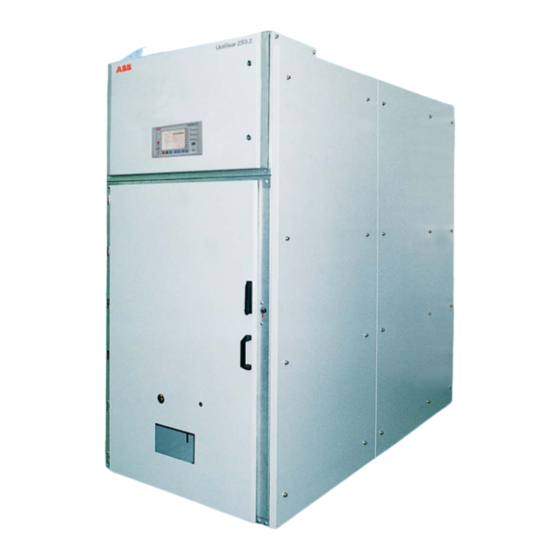
- Page 1 — I N S T R U C T I O N M A N U A L UniGear ZS3.2 Air-insulated medium voltage switchgear • Safety • Reliability • Flexibility • Economy...
-
Page 3: Table Of Contents
— Table of contents 1 Summary 006 – 007 2 Technical data 008 – 016 3 Switchgear panel structure and equipment installed 017 – 018 4 Dispatch and storage 019 – 031 5 Assembly of the switchgear at site 032 – 038 6 Operation of the switchgear 039 –... -
Page 4: For Your Safety
• Check that the personnel operating the apparatus have this instruction manual to hand as well as the necessary information for correct intervention • Responsible behavior safeguards your own and others’ safety For any requests, please contact the ABB Assistance Service. -
Page 5: Summary
• Increased ambient temperatures must be systems. Above and beyond this, the order-related compensated for in the design of the busbars data from ABB Xiamen Switchgear Co., Ltd. are and tee-off conductors, or the current carrying to be taken into account. -
Page 6: Technical Data
UniGear ZS3.2 I N S T R U C T I O N M A N U A L — 2 Technical data 2.1 Electrical data Standard: IEC/Chinese GB Russian GOST Rated voltage 36/40.5 Unorm.: 35 Umax.: 40.5 Rated power frequency withstand voltage/1 min... - Page 7 T E C H N I C A L D A T A — 2/1 Dimensions, without ventilation, front view — 2/2 Dimension, UniGear ZS3.2, …1600 A, section view 1200 — R(L1) Y(L2) B(L3) Service Test A Circuit-breaker compartment Position...
-
Page 8: Switchgear Panel Structure
UniGear ZS3.2 I N S T R U C T I O N M A N U A L — 3 Switchgear panel structure and equipment installed 3.1 Basic structure and variants side walls as result of embossing processing used. - Page 9 S W I T C H G E A R P A N E L S T R U C T U R E A N D E Q U I P M E N T I N S T A L L E D The switching operations (including manual Installation of surge arrestors is possible.
- Page 10 UniGear ZS3.2 I N S T R U C T I O N M A N U A L — • The circuit-breaker can only be opened manually VD4 vacuum circuit breakers are suitable for 3/1 VD4 in the service or test position when no control autoreclosing, and have exceptionally high —...
- Page 11 S W I T C H G E A R P A N E L S T R U C T U R E A N D E Q U I P M E N T I N S T A L L E D —...
- Page 12 UniGear ZS3.2 I N S T R U C T I O N M A N U A L — 3/5 UniGear ZS3.2, front view —...
- Page 13 S W I T C H G E A R P A N E L S T R U C T U R E A N D E Q U I P M E N T I N S T A L L E D — 3/6 UniGear ZS3.2 35.1...
- Page 14 UniGear ZS3.2 I N S T R U C T I O N M A N U A L — 3/8 Panel of type UniGear ZS3.2, rear side — 3/9 Circuit-breaker 30.1 35.3 compartment, door open, withdrawable 35.1 part removed —...
- Page 15 S W I T C H G E A R P A N E L S T R U C T U R E A N D E Q U I P M E N T I N S T A L L E D —...
- Page 16 UniGear ZS3.2 I N S T R U C T I O N M A N U A L — 3/15 Withdrawable 50.2 part with circuit- breaker, VD4, operating mechanism side 57.1 control wiring plug pluged at front 57.8 partition of the circuit-breaker —...
-
Page 17: Dispatch And Storage
D I S P A T C H A N D S T O R A G E — 4 Dispatch and storage 4.1 Condition on delivery Transport switchgear panels upright. The factory assembled switchgear panels are Only ever carry out loading operations checked at the works for completeness in terms when it has been ensured that all of the order and simultaneously subjected to... - Page 18 UniGear ZS3.2 I N S T R U C T I O N M A N U A L • Take care that the catch pins 51.1 on the inter- • Room temperature which does not fall below lock yoke 51 are engaged with the guiding -15°C...
-
Page 19: Assembly Of The Switchgear
ABB Xiamen Switchgear Co., Ltd.; it is usually laid If these conditions are not fulfilled, problems... - Page 20 UniGear ZS3.2 I N S T R U C T I O N M A N U A L — Structural data Table for figure 5/1 and 5/2: Rated voltage 36/40.5 Panel type UniGear ZS3.2 Panel equipment Withdrawable Panel width...
- Page 21 A S S E M B L Y O F T H E S W I T C H G E A R A T S I T E 5.4 Installation of the busbars and bushings • Prepare and secure cable sealing ends 16 in (Figures 3/6, 5/7 to 5/17) accordance with the manufacturer’s •...
- Page 22 UniGear ZS3.2 I N S T R U C T I O N M A N U A L — 5/1 Guideline structural data for foundation frame on concrete floor (for information only) (280)(280) (280)(280) Only for transformer panel (360)
- Page 23 3 Opening for control cables (instead of individual openings, continuous openings or drilled holes are possible) 5 Openings for power cables 7 Panel type UniGear ZS3.2 ...31.5 kA 8 Power cables 9 Projecting of floor frame: 5-12 mm above finished floor level...
- Page 24 UniGear ZS3.2 I N S T R U C T I O N M A N U A L — 5/4 For bolting the UniGear ZS3.2 panels together, threaded brushings are provided at the 1.11 right side near to the front and rear edges of the side walls.
- Page 25 A S S E M B L Y O F T H E S W I T C H G E A R A T S I T E — 5/8 Bushings with busbar mountings for busbar system with double D-profile, tee-off ...1600 A —...
- Page 26 UniGear ZS3.2 I N S T R U C T I O N M A N U A L — 5/10 Single rectangular copper busbar with single branch bar system (...1600 A) 8.4, 8.5, 8.6 — 5/10 8.3 Contact spring (for rectangle busbar) 8.4 Socket head bolt M6x16...
- Page 27 A S S E M B L Y O F T H E S W I T C H G E A R A T S I T E — 5/13 Contact spring installation 29.3 29.3 a) Check the contact spring 29.3 surface without any crease and b) Pull open the contact spring 29.3, insert it into the hole of busbar 3.
- Page 28 UniGear ZS3.2 I N S T R U C T I O N M A N U A L 29.3 e) Spring resilience checking: press the contact spring 29.3 down for around 10 mm, the contact spring 29.3 should be rebounded freely after loosen.
- Page 29 A S S E M B L Y O F T H E S W I T C H G E A R A T S I T E — 5/14 Busbar barriers 29.2 29.4 29.3 3.12 a) Detail of a busbar bushing, sectional view. Always check that there is proper contact between the metal tube in the bushing and the busbar via the contact spring.
- Page 30 UniGear ZS3.2 I N S T R U C T I O N M A N U A L — 5/15 Arrangement and bolting of single and double conductor busbars with single and double tee-off bars. Ensure that screws and...
- Page 31 2x100x10 for circuit-breaker insertion, optional. The rail on the guiding ramp must be in line with the guiding rail in the UniGear ZS3.2 panel. Cut place for sammel- schienen-system D 100 58.5 Lid for cover — 5/17 — 5/18...
-
Page 32: Operation Of The Switchgear
UniGear ZS3.2 I N S T R U C T I O N M A N U A L — 6 Operation of the switchgear Note on safety at work • Set the protective devices in the switchgear The relevant work and operating procedures are... - Page 33 O P E R A T I O N O F T H E S W I T C H G E A R 6.2.1 Withdrawable circuit-breaker part 6.2.2 Circuit breaker (Figures 3/2, 6/1 to 6/7) (Figures 6/1 to 6/5) Manual insertion from the test/disconnected For operation refer to Manual BA 483/02E, position to the service position:...
- Page 34 UniGear ZS3.2 I N S T R U C T I O N M A N U A L A distinction must be made between the low on all coupling components, e.g. with interface impedance system and the high impedance tester KSP system.
- Page 35 O P E R A T I O N O F T H E S W I T C H G E A R — 51.1 51.2 54.1 6/1 Withdrawable part with circuit-breaker, VD4, operating mechanism side — 6/2 Charging the 55.8 spring energy storage mechanism...
- Page 36 UniGear ZS3.2 I N S T R U C T I O N M A N U A L — 6/5 Interlock yoke with sliding handles 51.3 10.4 10.5 which will be moved inwards to release the circuit-breaker part for withdraw from the panel.
- Page 37 O P E R A T I O N O F T H E S W I T C H G E A R — 6/8 Earthing switch 14.3 operation mechanism. Duct cover 43.1 removed (seen from inside panel) — 6/9 Earthing switch operation mechanism (panel front side)
- Page 38 UniGear ZS3.2 I N S T R U C T I O N M A N U A L — 6/11 Earthing switch, EK6 mounted in the cable connection compartment shown in closed 6.10 position — 6/12 Bevel gear 14.1 14.1...
-
Page 39: Maintenance
VDE/IEC and of other technical (e.g. heavy pollution and aggressive atmosphere). authorities, and with other overriding instructions. It is recommended that ABB service The inspection should include but not be personnel be called in to perform servicing and... - Page 40 (with Isoflex Topas NB52) as a temporary remedy. It is advisable to 7.3.2 Replacement of components request advice from the ABB after-sales service department on permanent solutions to such Replacement of the isolating contact systems: unusual problems (Figures 7/1 to 7/4) •...
- Page 41 M A I N T E N A N C E • Thread M20, non-greased, at 200 Nm 7.4.2 Testing of interlock conditions (Figures 6/1 to 6/9) 7.4 Tests on withdrawable parts with 1. The withdrawable part must only be movable circuit-breakers of VD4 or HD4 from the test/disconnected position into the (Figures 3/12, 3/14, 3/15, 6/1 to 6/7)
- Page 42 GCE0007707P0100 • With the withdrawable part in the test/ (for general cleaning) disconnected position, it must be possible ABB directions for use to press slide 14.2 in front of the earthing BA 1002/E GCEA901002P0102 switch drive shaft 14.1 downwards to the •...
- Page 43 M A I N T E N A N C E — 7/1 Contact system sample for 2000 A to 3150 A — 7/2 Sliding the contact system onto the auxiliary arbour with the rear end first, schematic representation here for 1600 A —...
-
Page 44: Product Quality And
The following methods of disposal: End of life of product Disposal can either be carried out thermally in The ABB company is committed to complying an incineration plant or by storing on a waste with the relevant legal and other requirements site. - Page 48 No.885, FangShanXiEr Road, Xiang'an District, Xiamen, Fujian, 361101 Tel: 0592 602 6033 Fax: 0592 603 0505 ABB China Customer Service Hot Line TEL: 800-820-9696 / 400-820-9696 mail: cn-ep-hotline@abb.com www.abb.com © Copyright 2019 ABB. All rights reserved. Specifications subject to change without notice.