
Related Manuals for ABB OTM3200E4M230C-GE


Summary of Contents for ABB OTM3200E4M230C-GE
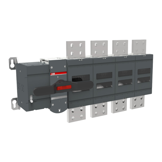
- Page 1 — I N S TA L L AT I O N A N D O P E R AT I N G I N S T R U C T I O N Motorized switch-disconnectors OTM3200E4M230C-GE...
-
Page 2: Table Of Contents
M O T O R I Z E D S W I T C H - D I S C O N N E C T O R S , O T M 3 2 0 0 E 4 M 2 3 0 C - G E —... -
Page 3: Operation
M OTO R I Z E D S W I TC H - D I S C O N N E C TO R S , OT M 3 2 0 0 E4 M 2 3 0 C - G E —... -
Page 4: Introduction
OTM3200E4M230C-GE. The instructive part is followed by a section on available accessories. This switch is intended for mounting in OTM3200E4M230C-GE, manufactured by GE POWER CONVERSION INDIA Pvt Ltd. Metallic enclosure and the dimension is 2x1x1 m. The minimum clearance between the switch and adjacent parts of the enclosure or other grounded components that may be mounted near the switch is 14 mm. -
Page 5: Product Overview
M OTO R I Z E D S W I TC H - D I S C O N N E C TO R S , OT M 3 2 0 0 E4 M 2 3 0 C - G E — 2. Product overview Motorized switch-disconnectors (type OTM3200E4M230C-GE) are suitable for remote control. You can operate the motorized switch-disconnectors either electrically by using the motor operator or manually by using the handle. The operation, either electrical or manual, can be chosen by the selector switch “Motor/Manual”... -
Page 6: Installation
M O T O R I Z E D S W I T C H - D I S C O N N E C T O R S , O T M 3 2 0 0 E 4 M 2 3 0 C - G E —... -
Page 7: Dimensional Drawings
M OTO R I Z E D S W I TC H - D I S C O N N E C TO R S , OT M 3 2 0 0 E4 M 2 3 0 C - G E —... -
Page 8: Connections
Mounting the connections to the motorized change-over switches OTM3200E4M230C-GE. The minimum connection busbars 5x100x10 = 5000mm^2 Cu and bridge busbars 1x80x15=1200mm^2 Cu, 1pc bridge busbar for each terminal. — 3.4 Mounting connections 50...75 Nm 443-664 lb.in +(-) -(+) +(-) -(+) Figure 3.5 Circuit 3 OTM3200E4M230C-GE... -
Page 9: Supporting Distances
M OTO R I Z E D S W I TC H - D I S C O N N E C TO R S , OT M 3 2 0 0 E4 M 2 3 0 C - G E —... -
Page 10: Labelling
M O T O R I Z E D S W I T C H - D I S C O N N E C T O R S , O T M 3 2 0 0 E 4 M 2 3 0 C - G E —... -
Page 11: Connecting
M OTO R I Z E D S W I TC H - D I S C O N N E C TO R S , OT M 3 2 0 0 E4 M 2 3 0 C - G E —... -
Page 12: Operating
M O T O R I Z E D S W I T C H - D I S C O N N E C T O R S , O T M 3 2 0 0 E 4 M 2 3 0 C - G E —... - Page 13 M OTO R I Z E D S W I TC H - D I S C O N N E C TO R S , OT M 3 2 0 0 E4 M 2 3 0 C - G E Turn the Motor/Manual selection switch to the Motor (M) position, see Figure 5.2.
-
Page 14: Impulse Control
M O T O R I Z E D S W I T C H - D I S C O N N E C T O R S , O T M 3 2 0 0 E 4 M 2 3 0 C - G E 5.1.1 Impulse control When using impulse control, the switch-disconnector is controlled by electric impulses. -
Page 15: Manual Operation Using The Handle
M OTO R I Z E D S W I TC H - D I S C O N N E C TO R S , OT M 3 2 0 0 E4 M 2 3 0 C - G E —... -
Page 16: Locking
M O T O R I Z E D S W I T C H - D I S C O N N E C T O R S , O T M 3 2 0 0 E 4 M 2 3 0 C - G E —... -
Page 17: Locking The Manual Operation
M OTO R I Z E D S W I TC H - D I S C O N N E C TO R S , OT M 3 2 0 0 E4 M 2 3 0 C - G E 5.3.2 Locking the manual operation By default, manual operation can only be locked to position 0. - Page 18 M O T O R I Z E D S W I T C H - D I S C O N N E C T O R S , O T M 3 2 0 0 E 4 M 2 3 0 C - G E The following chart shows the locking state information (the voltage on motor operator supply needed)* Man.
-
Page 19: Technical Data
M OTO R I Z E D S W I TC H - D I S C O N N E C TO R S , OT M 3 2 0 0 E4 M 2 3 0 C - G E —... -
Page 20: Accessories
M O T O R I Z E D S W I T C H - D I S C O N N E C T O R S , O T M 3 2 0 0 E 4 M 2 3 0 C - G E —... -
Page 21: Mounting Of Test Auxiliary Contacts
M OTO R I Z E D S W I TC H - D I S C O N N E C TO R S , OT M 3 2 0 0 E4 M 2 3 0 C - G E 7.1.2 Mounting of the test auxiliary contacts Main contact Test contact (NO) -
Page 22: Phase Barriers
M O T O R I Z E D S W I T C H - D I S C O N N E C T O R S , O T M 3 2 0 0 E 4 M 2 3 0 C - G E —... - Page 24 — Contact us ABB Oy P.O. Box 622 FI-65101 Vaasa Finland abb.com/lowvoltage © Copyright 2022 ABB. All rights reserved. Specifications subject to change without notice.