
Related Manuals for ABB ATS022


Summary of Contents for ABB ATS022
- Page 1 Doc. No. 1SDH000760R0002 - L8884 Automatic transfer switch ATS022 Installation and operating instructions...
-
Page 3: Table Of Contents
Introduction ........................6 Product overview ...........................6 Application scenarios ........................7 Applications of device ATS022 ..................8 Switching Main Line – Emergency generator (2CBs) ..............9 Non priority loads control (NPL) ....................10 Control of two independent power supply lines separated by Tie (3CBs Bus Tie) .....14 Automatic switching without inverse procedure .................15... -
Page 4: Safety Notes
If there are doubts about safe use, the unit must be put out of service. The automatic transfer switch ATS022 must be prevented from operating the circuit breakers before: • accessing the circuit breakers • performing maintenance on circuit breakers or any electrical circuits powered by them •... -
Page 5: Explanation Of Abbreviations And Terms
2. Explanation of abbreviations and terms Installation and operating instructions, ATS022 2. Explanation of abbreviations and terms 2.1. General information ATS: Automatic Transfer Switch; automatic switching device. ATS022: ATS of the ATS02x series, version with display and Modbus communication. Circuit Breaker; low voltage automatic Circuit Breaker. -
Page 6: Introduction
• utilisation in single-phase systems with Un 57,5…109VAC A 24VDC ….110VDC auxiliary safety power supply can be used (-10%, +15%). ATS022 can be used in systems with rated frequency 50Hz, 60Hz, 400Hz, 16 2/3 Hz that can be set from the menu. -
Page 7: Application Scenarios
• control of two independent power supply lines separated by Bus Tie (3CBs Bus Tie) The ATS022 also makes it possible to select which of the lines is the main one and which one is secondary, also with the system running. -
Page 8: Applications Of Device Ats022
Installation and operating instructions, ATS022 Applications of device ATS022 4. Applications of device ATS022 The ATS022 device controls all the switching sequences by applying the time delays that can be set: Time delays Description Value Opening delay of main line CB after detection of a fault in the mains (Generator is not in use). -
Page 9: Switching Main Line - Emergency Generator (2Cbs)
4.2 Switching Main Line – Emergency generator (2CBs) Description In case of main line failure ATS022 automatically starts up an emergency generator and, as soon as power on the generator side is available, ATS022 starts the automatic switching procedure. Figure 4.3: 2CBs application layout –... -
Page 10: Non Priority Loads Control (Npl)
4.3 Non priority loads control (NPL) Description In case of main line failure the ATS022 starts the switching procedure and controls the non priority loads by opening closing circuit breaker CB3. ATS022 acquires the CB3 open/close status from the dedicated input DI11 and commands the opening and closing by activating output DO11. - Page 11 Installation and operating instructions, ATS022 Applications of device ATS022 configuration requires configuration with 2 lines or with a line and an emergency generator. Figure 4.5: Application layout 3CBs NPL BUSTIE Figure 4.6: Application layout 3CBs NPL 1SDH000760R0002...
- Page 12 Installation and operating instructions, ATS022 Applications of device ATS022 Time diagrams Line 1 ok CB1 CLOSED Gen start Line 2 ok CB2 CLOSED CB3 CLOSED TGOFF Figure 4.7: Application time diagram 3CBs NPL BUS TIE - generator in use Line 1 ok...
- Page 13 Installation and operating instructions, ATS022 Applications of device ATS022 Line 1 ok CB1 CLOSED Gen start Line 2 ok CB2 CLOSED CB3 CLOSED TGOFF Figure 4.9: Application time diagram 3CBs NPL- generator in use Line 1 ok CB1 CLOSED Line 2 ok...
-
Page 14: Control Of Two Independent Power Supply Lines Separated By Tie (3Cbs Bus Tie)
Lines LN1 and LN2 supply two different sections of the plant separated by a bus tie circuit breaker CB3, normally open. In case of failure of one of the two supply lines, ATS022 closes CB3; the available line thus powers both the sections downline. When the line is restored ATS022 restores the normal plant conditions by opening CB3. -
Page 15: Automatic Switching Without Inverse Procedure
CB1 is opened. ATTENTION If ATS022 is not powered by the auxiliary supply and by any of the two lines the device waits for at least one of the two lines (5) to return before proceeding with the switching procedure (6). -
Page 16: Line Priority Selection
Applications of device ATS022 Line Priority Selection Description ATS022 allows selection of the main line by means of the menu on the display. The following selections are possible: - main line: Line LN1 - main line: Line LN2 (selection possible only if generator is not in use) -
Page 17: Using The Automatic Transfer Switch
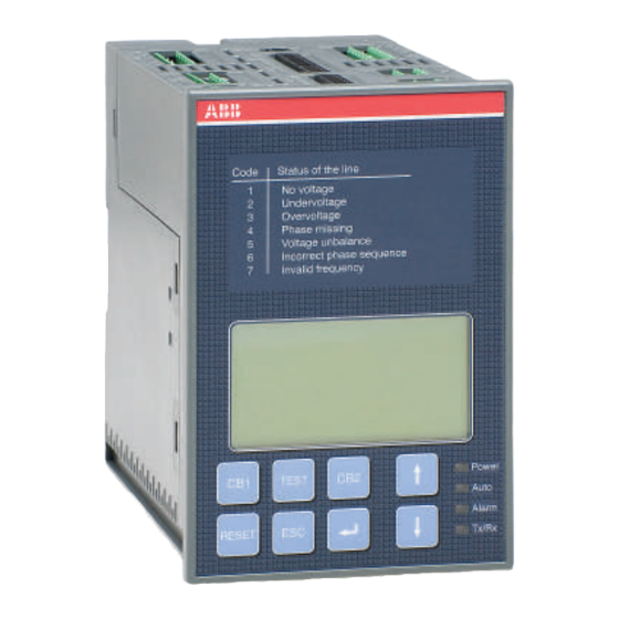
Voltage unbalance Incorrect phase sequence Invalid frequency R E S E T Figure 5.1: Description of ATS022 front panel interface Ref. Description CB1: pushbutton for opening/closing circuit breaker CB1 CB2: pushbutton for opening/closing circuit breaker CB2 CB3: CB3 opening/closure procedure graphic indication (combination of UP-DOWN keys for at... -
Page 18: Led Indicators
1 minute). When the Powersave period ends, the LED switches off and the device awaits a line voltage. The moment the normal or the emergency line is restored, with ATS022 in automatic, the unit analyses the conditions of the lines monitored and the status of the circuit breakers and proceeds with the switching operation in accordance with the situation concerned. -
Page 19: Keypad Keys
TEST key Press the TEST key to set the test modes of the direct and inverse switching sequences. ATS022 must be in the manual position. To exit TEST mode press RESET. Enter key Used for confirming the action or entry to the menu. -
Page 20: Setting The Operating Modes
To select the Automatic operating mode of unit ATS022: a. Make sure the Power LED is On, see Figure 5.3/1 b. Press RESET once, see Figure 5.3/2. If the Auto LED is ON, the automatic transfer switch ATS022 is in Automatic mode, see Figure 5.3/3 c. -
Page 21: Graphic Display
Installation and operating instructions, ATS022 Using the automatic transfer switch 5.5 Graphic Display LN1: 1 TBS.. LN2: 1 Figure 5.4: Description of ATS022 display Ref. Description LN1: line 1 LN2: line 2 CB1 status graphic indicator CB2 status graphic indicator... -
Page 22: Ln1 And Ln2 Lines Status Indication
3P + N configuration. Table 5.3: Description of line status codes ATS022 5.5.2 Browsing through the Menu Press Enter to access the main Menu. Three different levels of configuration of the unit can be accessed from the main menu: Figure 5.5:... - Page 23 240V/138V - 277V/160V - 347V/200V - 400V/230 V 380V/220V - 400V/230V - 415V/240V - 440V/254V - 480V/277V Table 5.4: Description of parameters of lines ATS022 - Type of application Type of application Value Factory settings 2CBs / 3CBs NPL opening only / 3CBs NPL...
- Page 24 Table 5.9: Description of Modbus parameters ATS022 - Language and backlit display Function Value Factory settings Backlighting duration Always On, 0…59s, step 1s, 1,2,3…30min, step 1min Always On English/Italian/German/French/Spanish/Finnish/ Language English Russian/Chinese Table 5.10: Description of language and backlighting ATS022 1SDH000760R0002...
- Page 25 The log is cleared by selecting Clear Log and pressing Enter. Diagnostics Measured Values Alarm Log SW: 1A SN: 12345678 Figure 5.5: Description of diagnostics menu ATS022 Figure 5.6: diagnostics – values measured page ATS022 Figure 5.7: diagnostics – Alarms Log page ATS022 1SDH000760R0002...
-
Page 26: Using Pushbuttons In Manual Mode
Installation and operating instructions, ATS022 Using the automatic transfer switch 5.6 Using pushbuttons in manual mode Opening/Closing circuit breakers CB1, CB2 In manual mode the circuit breakers can be controlled by means of pushbuttons CB1 and CB2. In case of a fault, the alarms are activated by the same methods as those for the automatic switching sequence. -
Page 27: Test Modes
This test mode makes it possible to test only the generator start and stop with the plant running without opreating the circuit breakers on the line in any manner whatsoever, only if the ATS022 is set with the generator in use, otherwise the Gen Set Test is not performed. -
Page 28: Modbus Communication
ATS022 that are remotly available. In the ABB library it is also possible to download the software ABB EKIP connect 2 that enables a rapid and easy remote management of the measures , parameters, and the commands of ATS022. -
Page 29: Input And Output Signals
- Time TL: time that the fault is present on both lines after which the contact is activated. - Function DO7: the parameter available on ATS022 is a number in decimal format that, if converted into binary, allows 6 bits to be managed corresponding to the types of alarms (bit set to 0= alarm deactivated;... - Page 30 The Unbalance alarm also includes cases of undervoltage or overvoltage (for example, the drop of one phase in a 3P or 3P + N system). In the absence of voltages, ATS022 cannot calculate the angle between the various phases and therefore it considers this condition as: Incorrect phase sequence.
-
Page 31: Input Signals
DI3 Switching Logic Activation/Deactivation Input DI3 is used for enabling/disabling the switching logic. The function may be used for integrating generic alarms coming from the plant the presence of which leads to disabling of ATS022 automatic switching logic. • DI3 open: logic disabled •... - Page 32 When the circuit breaker is inserted: • the position indication contact closes • the switching logic is re-enabled • Alarm LED switches Off • ATS022 operates in manual mode • contact DO10 is closed • Alarm contact DO6 is opened • contact DO12 is opened •...
- Page 33 Open =gen start; Closed = gen stop Closed =gen start; Open = gen stop The DI10 contact programmed as a generator starting override is active with ATS022 configured with priority line LN1 and with backswitching. If one of these conditions does not exist, the option is not available or, if activated previously, will be automatically DISABLED.
- Page 34 • LN1 present: DI10 determines the activation and deactivation of the generator. • Switching in progress or line LN2 present: DI10 is ignored by ATS022. When changing over from automatic to manual, DI10 is handled differently depending on the initial state of the command to the generator: •...
- Page 35 Installation and operating instructions, ATS022 Input and output signals Linea 2 ATS022 Line 2 Linea 1 Linea 2 Line 1 Ligne 2 Linea 1 Leitung 2 Ligne 1 Leitung 1 Uscita per controllo Gen Start/Stop Output to control Gen Start/Stop...
- Page 36 Installation and operating instructions, ATS022 Input and output signals Connectors Description DI/DO Type X11:1 Normal Line LN1: L1 X11:2 Normal Line LN1: L2 X11:3 Normal Line LN1: L3 X11:4 Normal Line LN1: N X12:1 Emergency Line LN2: L1 X12:2 Emergency Line LN2: L2...
- Page 37 CB2 trip input 0=CB trip; I=no CB trip X32:8 CB1 trip input 0=CB trip; I=no CB trip X32.9 X51:1 Modbus DATA B X51:2 Modbus DATA A X52:3 Modbus GND Earth connection Table 6.2: Description of function and type connector ATS022 1SDH000760R0002...
-
Page 38: Technical Data
In case of rated frequency 16 2/3 Hz, an auxiliary safety power supply must be used. If the rated voltage is greater than 100 VAC external transformers must be used. If the ATS022 is used in environments with extremely low temperatures (less than - 10°C) it is advisable to use a safety auxiliary power supply to avoid display problems of the graphic display. -
Page 39: Installation Of Device Ats022
Installation of device ATS022 8. Installation of device ATS022 The automatic transfer switch ATS022 can be mounted on the front of the panel door or on DIN rail. 8.1. Door-mounted Automatic Transfer Switch ATS022 The Automatic Transfer Switch ATS022 can be door-mounted as shown in Figure 8.1. -
Page 40: Din Rail-Mounted Automatic Transfer Switch Ats022
Installation and operating instructions, ATS022 Installation of device ATS022 8.2. DIN rail-mounted Automatic Transfer Switch ATS022 The automatic transfer switch ATS022 can be mounted on a 35mm DIN rail as shown in Figure 8.2. 35mm EN 50022 Togliere Figure 8.2:... -
Page 41: Regulatory Standards
Regulatory standards Installation and operating instructions, ATS022 9. Regulatory standards ATS022 conforms to the following regulatory standards: • European Directive 73/23 “LVD – Low Voltage Directive” • EN 50178 electronic equipment for use in power Installations • EN-IEC 62103 electronic equipment for use in power Installations •... -
Page 42: Troubleshooting
10. Troubleshooting Installation and operating instructions, ATS022 10. Troubleshooting The alarms are shown by means of a message on the ATS022 display. The Alarm messages are shown in the Table below: Table 10.1: Alarms ATS022 Alarm Fault Action circuit breaker CB1 on normal line... - Page 43 Due to possible development of Standards as well as of materials, the characteristics and dimensions specified in this Installation and operating instructions may be considered as binding only after confirmation by ABB SACE Division. © Copyright 2011-2016 ABB. All rights reserved.