
Related Manuals for ABB SYN 5201


Summary of Contents for ABB SYN 5201
- Page 1 3BHS109762 E01 Rev. D Edition: december 2011 ® SYNCHROTACT Operating Instructions SYN 5201 SYN 5202...
- Page 2 Operating Instructions SYN 5201/SYN 5202 2011 ABB Switzerland Ltd Turgi We reserve all rights in this document and in the information contained therein. Reproduction, use or disclosure to third parties without express authority is strictly forbidden. Document No Art Part...
-
Page 3: Table Of Contents
Operating Instructions SYN 5201/SYN 5202 Content GENERAL INFORMATION ..................5 FUNCTIONAL PRINCIPLE ................... 7 HARDWARE CONSTRUCTION ................. 25 PARAMETERS, ACTUAL VALUES, EVENTS ............31 ENGINEERING INSTRUCTIONS ................67 INSTALLATION AND DISPOSAL ................77 OPERATING INSTRUCTIONS ................... 79 COMMISSIONING ...................... 91 MAINTENANCE AND FAULTS ................ - Page 4 Operating Instructions SYN 5201/SYN 5202 Document No Art Part Language Revision page 3BHS109762 E01 ABB Switzerland Ltd Template: CHIND Techn doc stand, A4 P de, R1.DOT; Filename: 3BHS109762E01 D.doc; Print: 12/6/2011 5:48:00 PM; Save: 12/1/2011 2:37:00 PM; CHIND No. 3BHS109763 ZAB D14 Rev. -; I-Q...
-
Page 5: General Information
SYNCHROTACT 5 equipment. The User Manual provides the information required in order to install, commission and operate the SYNCHROTACT 5 device of types SYN 5201 and SYN 5202. Marking of text sections... - Page 6 Operating Instructions SYN 5201/SYN 5202 Document No Art Part Language Revision page 3BHS109762 E01 ABB Switzerland Ltd Template: CHIND Techn doc stand, A4 P de, R1.DOT; Filename: 3BHS109762E01 D.doc; Print: 12/6/2011 5:48:00 PM; Save: 12/1/2011 2:37:00 PM; CHIND No. 3BHS109763 ZAB D14 Rev. -; I-Q...
-
Page 7: Functional Principle
The device is designed for system frequencies of either 50/60 Hz or 16 SYN 5201 is a single-channel synchronizing device whose component choice and software design provides the highest security against incorrect paralleling. - Page 8 Operating Instructions SYN 5201/SYN 5202 Paralleling functions The automatic paralleling process can basically be divided into four function blocks: 1. Measuring 2. Voltage and frequency matching 3. Monitoring of paralleling conditions 4. Paralleling command generation In the following figure, the block circuit diagram of the basic paralleling functions of SYNCHROTACT 5 is simplified and shows a single-channel configuration.
- Page 9 Operating Instructions SYN 5201/SYN 5202 2.2.1 Measuring The following measured variables are generated from the two single-phase measuring voltages: Voltage U1, U2 U1 is the reference voltage e.g. line U2 is the adjustable voltage e.g. generator. Frequency f1, f2 f1 is the reference frequency f2 is the adjustable frequency.
- Page 10 Operating Instructions SYN 5201/SYN 5202 Voltage measurement (SYN 5202: channel 1) The two input voltages U1 and U2 are passed to the processor via high-impedance input resistors, differential amplifiers, low-pass filters and A/D converters. SYNCHROTACT 5 PCB: SYN 5012 PCB: SYN 5011...
- Page 11 Operating Instructions SYN 5201/SYN 5202 2.2.2 Voltage and frequency matching Working range of the voltage matcher If the voltage U1 is in the range between Umin and Umax and the voltage U2 is greater than U0max the adjusting commands are released. The direction of the adjusting commands depends on the polarity of ...
- Page 12 Operating Instructions SYN 5201/SYN 5202 Voltage matcher with variable pulse times The voltage matcher issues a command the length of which is proportional to the current voltage difference. The proportionality factor dU/dt can be adapted to the voltage regulator. The voltage matcher aims at a value in the middle of the set tolerance band.
- Page 13 Operating Instructions SYN 5201/SYN 5202 Frequency matcher with variable pulse durations The frequency matcher issues a command the length of which is proportional to the current slip. The proportionality factor df/dt can be adapted to the governor. The frequency matcher aims at a value midway between the nearer slip limit and zero. The adjusting command length tpf is: ...
- Page 14 Operating Instructions SYN 5201/SYN 5202 Frequency matcher with variable intervals The function INVERSE f changes the way the frequency matcher functions. The pulses are now always the same length, but the intervals are inversely proportional to the slip. Pulse length: adjustable by means of the parameter tp fmin: tp = tp fmin...
- Page 15 Operating Instructions SYN 5201/SYN 5202 The monitoring of the paralleling conditions (CHK RELEASE) releases the paralleling command if the following conditions are fulfilled simultaneously: the releasing signal for dead bus (digital input) is issued the zero voltage(s) does not exceed the set threshold U0max ...
- Page 16 Operating Instructions SYN 5201/SYN 5202 Synchronous sources and no-voltage lines It is called synchronous sources, if the two lines to be paralleled are synchronous before the circuit breaker is closed. If the paralleling conditions (CHK RELEASE) or dead bus conditions (DB RELEASE) are fulfilled during the monitoring time t supervis, a command is generated immediately after the expiry of t supervis.
- Page 17 Operating Instructions SYN 5201/SYN 5202 2.3.2 TEST U-Match This test function proceeds as follows: The generator voltage is adjusted until this lies in the range between 95 and 97% of the line voltage, then the adjusting pulse is discontinued. Ten seconds after the first adjusting pulse, the voltage difference U0 is measured, then a Higher command U+ lasting 5 s is given.
- Page 18 Operating Instructions SYN 5201/SYN 5202 Operating statuses, operating modes and sequences of the synchronization process 2.4.1 Operating statuses No. Status Remarks Blocked with BLOCKED & There is a fault, the device is blocked error ERROR Blocked The device is in setting mode or in test mode, i.e.
- Page 19 Operating Instructions SYN 5201/SYN 5202 The first time the device is powered up, the device is in BLOCKED status once the Note auxiliary voltage is present. By means of a corresponding command, the device can be set to READY status using the PC tool or the built-in control unit. On the next occasions the device is powered up, it goes directly into READY status.
- Page 20 Operating Instructions SYN 5201/SYN 5202 SYN 5201 and SYN 5202 can be operated purely as a synchrocheck in that the command generation, the voltage and frequency matcher are switched off in the parameter set. If the same circuit breaker is to be switched, once automatically and once manually using synchrocheck in alternation, and in both cases the same synchronizer is to be used, this can be achieved through configuration of the inputs and outputs.
- Page 21 Operating Instructions SYN 5201/SYN 5202 Stored data The parameter values are permanently stored in a non-volatile memory, and are not affected by ageing or failure of the auxiliary voltage. The parameter settings can only be changed by means of write commands.
- Page 22 Operating Instructions SYN 5201/SYN 5202 Control options With the SYNCHROTACT 5, a distinction is made between service control and operating control: Service control for commissioning and maintenance: 1. Controls on the unit: keypad & LCD (standard) 2. Local control using PC (SynView): direct link SYNCHROTACT to PC 3.
- Page 23 Operating Instructions SYN 5201/SYN 5202 Transmitted signals via interfaces 2.9.1 Service interface The service interface is operated using SynView. The transmitted information is therefore identical to the SynView functions. Essentially, these are: Parameter settings (read and write) Put device in READY mode, block device, cancel errors ...
- Page 24 Operating Instructions SYN 5201/SYN 5202 Document No Art Part Language Revision page 3BHS109762 E01 ABB Switzerland Ltd Template: CHIND Techn doc stand, A4 P de, R1.DOT; Filename: 3BHS109762E01 D.doc; Print: 12/6/2011 5:48:00 PM; Save: 12/1/2011 2:37:00 PM; CHIND No. 3BHS109763 ZAB D14 Rev. -; I-Q...
-
Page 25: Hardware Construction
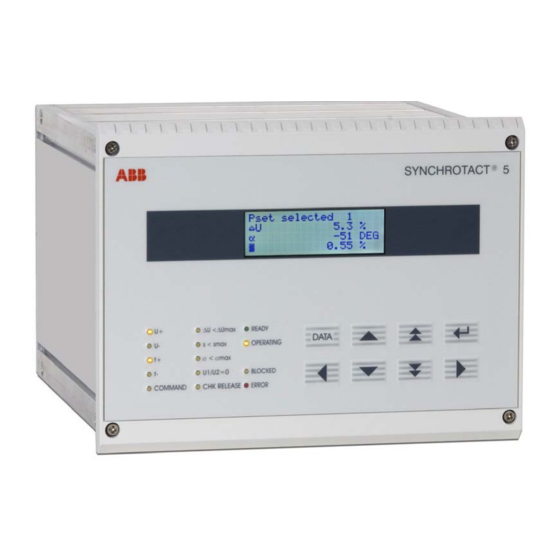
Operating Instructions SYN 5201/SYN 5202 Hardware construction Type code for devices Document No Art Part Language Revision page 3BHS109762 E01 ABB Switzerland Ltd Template: CHIND Techn doc stand, A4 P de, R1.DOT; Filename: 3BHS109762E01 D.doc; Print: 12/6/2011 5:48:00 PM; Save: 12/1/2011 2:37:00 PM; CHIND No. 3BHS109763 ZAB D14 Rev. -; I-Q... - Page 26 SYN 5201/SYN 5202 Front panel On the front panel of the SYN 5201 or SYN 5202 there is a block of status displays, as well as eight keys and the liquid crystal display (LCD) of the built-in service controls. Status displays (LED)
- Page 27 Operating Instructions SYN 5201/SYN 5202 Built-in service controls All manipulations, such as viewing/altering parameters, viewing actual values etc., can be carried out using the built-in service controls. The keypad consists of 8 keys with the following functions: DATA Selection key for adjusting the parameter values...
- Page 28 Operating Instructions SYN 5201/SYN 5202 Rear of unit The electrical connections are made on the rear of the unit by means of screwed connectors and spring-clip terminals. Measuring inputs With SYN 5202, the measuring inputs are passed to a separate connector for each channel.
- Page 29 Operating Instructions SYN 5201/SYN 5202 Printed circuit boards The devices consist of the following printed circuit board modules SYN 5010 communications board (option) Mount of a slot for the operating remote control interface. SYN 5011 processor and electronics power supply...
- Page 30 Operating Instructions SYN 5201/SYN 5202 Document No Art Part Language Revision page 3BHS109762 E01 ABB Switzerland Ltd Template: CHIND Techn doc stand, A4 P de, R1.DOT; Filename: 3BHS109762E01 D.doc; Print: 12/6/2011 5:48:00 PM; Save: 12/1/2011 2:37:00 PM; CHIND No. 3BHS109763 ZAB D14 Rev. -; I-Q...
-
Page 31: Parameters, Actual Values, Events
Operating Instructions SYN 5201/SYN 5202 Parameters, Actual values, Events Overview 4.1.1 Menu structure Synchrocheck Configuration Parameter set 1 Actual value Event memory 1 Digital inputs 1 Actual value calibration 1 Synchrocheck parameters 2 Command formation Event memory 2 Digital outputs... -
Page 32: Operating Instructions
Operating Instructions SYN 5201/SYN 5202 4.1.2 Event logger The events are displayed in the following format (for meaning, see also section 9): Line number Timestamp Event code hh:mm:ss Cyyy 4.1.3 Actual values The following table shows the actual values and their position in the menu:... - Page 33 Operating Instructions SYN 5201/SYN 5202 Parameter sets 1 to 7 1. Actual value calibration “Calibrate act values“ Parameter name Symbol Range/resolution Unit Default setting of all parameter sets Nominal voltage 50 to 130 Nominal frequency , 50, 60 Voltage tuning UOffset...
- Page 34 Operating Instructions SYN 5201/SYN 5202 4.1.5 Configuration parameters “Config parameters“ (option) These allow different functions to be assigned to the inputs and outputs (see also section 4.2.8 and 5.4). “Digital inputs “ Parameter name Symbol Range/resolution Unit Default setting Digital input 1...
- Page 35 Operating Instructions SYN 5201/SYN 5202 Parameter settings 4.2.1 Parameter group Actual Value Calibration Nominal voltage Un The nominal voltage is set in volts. The nominal voltage is plant-dependent. It is typically 58 (100/ 3 ); 64 (110/ 3 ); 100; 110 VAC, but can also have a different value.
- Page 36 Operating Instructions SYN 5201/SYN 5202 4.2.2 Parameter group Command Generation Test function for determining the paralleling time TEST ton When working on high voltage circuits, it is essential that the corresponding regulations on working on high voltage installations are complied with: The test function closes the circuit breaker.
- Page 37 Operating Instructions SYN 5201/SYN 5202 Procedure: 1. Pre-settings: - Set t on to 100 ms as an approximation - Reduce smax temporarily to the range from 0.1 to 0.2 % 2. All other commissioning work (especially calibration of the measuring voltages) must have been completed.
-
Page 38: Syn 5201/Syn
Operating Instructions SYN 5201/SYN 5202 Multiple commands MULTIPLE CMD With this setting one can select whether the synchronizer should only give one command or should always give a command if all conditions are fulfilled. In synchrocheck operation, i.e. with command generation switched off (tp on = OFF or 0), MULTIPLE CMD has no influence. - Page 39 Operating Instructions SYN 5201/SYN 5202 d) Paralleling of asynchronous lines: If two lines do not form a ring connection, the slip limits are restricted by the current limit permitted after paralleling. If the flow of power in a particular direction is to be avoided, the corresponding slip limit must be set to zero.
- Page 40 Operating Instructions SYN 5201/SYN 5202 The maximum phase shift ± max permitted for paralleling is calculated from the greatest phase shift which occurs plus a reserve. ± max is limited by the current i T = f(U1, U2, ) flowing after paralleling and if the flow of power in a particular direction is to be avoided.
- Page 41 Operating Instructions SYN 5201/SYN 5202 A misinterpretation of the measurement can lead to serious damage to the plant. If no- Caution voltage lines are detected, it is essential to make sure that the measuring circuits (voltage transformers, fuses and input cables) are functioning 100 % correctly. Only then should the release signal Release DB be given.
- Page 42 Operating Instructions SYN 5201/SYN 5202 DATA 9. Write value into the random access memory by pressing: & 10. Return to TEST U-Match, set this to OFF and confirm with & DATA 11. Temporarily set SYNCHROTACT 5 to “Ready“and block again. This writes all parameter settings into the ROM.
- Page 43 Operating Instructions SYN 5201/SYN 5202 11. Block SYNCHROTACT 5, set calculated value and set to Ready again 12. Bring voltage difference outside of the tolerance band 13. Start synchronizing process 14. Following the first voltage adjusting command, the voltage difference must lie approximately in the middle of the tolerance band.
- Page 44 Operating Instructions SYN 5201/SYN 5202 Once started, the test function is automatically cancelled if s reaches 6 %. Caution Nonetheless, it is recommended that you prepare for any manual cancellation by noting the following key combination: &...
- Page 45 Operating Instructions SYN 5201/SYN 5202 Procedure: Prevent the circuit breaker from closing while work is being carried out (circuit breaker in Test position, unplug connector -X6 for the paralleling commands on the SYNCHROTACT 5,...) Temporarily switch off voltage matcher: set dU/dt = 0 and write into the random access memory.
- Page 46 Operating Instructions SYN 5201/SYN 5202 Minimum pulse time tp fmin The minimum frequency adjusting pulse should be set as short as possible taking into account the manufacturer‘s specifications for the final control element. Usual setting value: tp fmin = 0.05 s.
-
Page 47: Digital Input
Operating Instructions SYN 5201/SYN 5202 4.2.8 Configuration parameters (Option) Digital inputs I1 to I7 and digital outputs O1 to O7 Normally, the configuration is fixed prior to commissioning. The settings are therefore based on the project planning data. The following table shows all possible functions for the inputs :... - Page 48 Operating Instructions SYN 5201/SYN 5202 The following table shows all possible functions for the outputs : Setting Function Remarks value Paralleling point 1 Paralleling point 2 Paralleling point 3 The relay is operated if the corresponding Paralleling point 4 paralleling point is active, i.e. selected, and Paralleling point 5 the synchronizing process is started.
-
Page 49: Synchrocheck
Operating Instructions SYN 5201/SYN 5202 Setting Function Remarks value U1<U0max These signals can only be active in U2<U0max ‘OPERATING‘ status or in ‘TEST‘ mode U1 and U2<U0max (configurable). U1 or U2<U0max 4.2.9 Synchrocheck parameters (SYN 5202 only) The synchrocheck parameter settings are based on the highest setting value of the corresponding parameters of all the used parameter sets. -
Page 50: Digital Input
Operating Instructions SYN 5201/SYN 5202 Addressing and configuration of the operating interface 4.3.1 Addressing Modbus RTU 28 words, each with 16 bits, are transmitted. The addressing is as follows: Add- Content Word type Direction Format Scaling ress trans- mission read and... -
Page 51: Digital Input
Operating Instructions SYN 5201/SYN 5202 Resolution of the bit-coded words into individual binary signals: Address 1 (Index 0): Binary signal Start Stop Release DB Reset Blocking input BLK REM (read only!) Configurable digital input 1 (only with SYN 5014) Configurable digital input 2 (only with SYN 5014) -
Page 52: 3Bhs109762 E01
Operating Instructions SYN 5201/SYN 5202 4.3.2 Configuring Modbus RTU The configuration of the Modbus RTU is carried out using 14 DIP switches. The three LEDs on the left next to the DIP switches are used for the status display. The device has to be restarted each time the configuration is changed (switch auxiliary Note voltage off and on again). -
Page 53: Digital Input
Operating Instructions SYN 5201/SYN 5202 4.3.3 Addressing Profibus DP 28 words, each with 16 bits, are transmitted. The addressing is as follows: Add- Content Word type Direction Format Scaling ress trans- mission Digital inputs Bit-coded read and write* Digital outputs... -
Page 54: Digital Input
Operating Instructions SYN 5201/SYN 5202 Resolution of the bit-coded words into individual binary signals: Address 1 (Index 0): Binary signal Start Stop Release DB Reset Blocking input BLK REM (read only!) Configurable digital input 1 (only with SYN 5014) Configurable digital input 2 (only with SYN 5014) -
Page 55: Abb Abb Switzerland Ltd
Operating Instructions SYN 5201/SYN 5202 4.3.4 Configuring Profibus DP The configuration of the Profibus is carried out using two DECIMAL switches. The switch on the left is x10 and that on the right x1. The device has to be restarted each time the configuration is changed (switch auxiliary Note voltage off and on again). -
Page 56: Actual Value U
Operating Instructions SYN 5201/SYN 5202 4.3.5 Addressing Lon-Bus 29 words, each with 16 bits, are transmitted. The addressing is as follows: Add- Content Word type Direction Format Scaling Signal name ress of trans- mission Digital inputs Bit-coded read* NV_Syn5_inputs_out Digital outputs... -
Page 57: Digital Input
Operating Instructions SYN 5201/SYN 5202 Resolution of the bit-coded words into individual binary signals: Address 1 (Index 0): Binary signal Start Stop Release DB Reset (cancel fault and set to "READY") Blocking input BLK REM (read only!) Configurable digital input 1 (only with SYN 5014) -
Page 58: Abb Abb Switzerland Ltd
Operating Instructions SYN 5201/SYN 5202 It is practical to read the signals for the addresses 4 to 11 by polling, since otherwise the Note insufficient steadying of the measured values places a heavy load on the fieldbus (worst case: a telegram every 20 ms). The measured value in Operating status is of the greatest interest. - Page 59 Operating Instructions SYN 5201/SYN 5202 4.3.7 IEC 61850 Data model Document No Art Part Language Revision page 3BHS109762 E01 ABB Switzerland Ltd Template: CHIND Techn doc stand, A4 P de, R1.DOT; Filename: 3BHS109762E01 D.doc; Print: 12/6/2011 5:48:00 PM; Save: 12/1/2011 2:37:00 PM; CHIND No. 3BHS109763 ZAB D14 Rev. -; I-Q...
-
Page 60: Digital Output
Operating Instructions SYN 5201/SYN 5202 4.3.8 SYNCHROTACT 5 - specific logical nodes and their application Contents Remarks RSYN10 General Data Standard RSYN21 Paralleling point 1 Standard RSYN22 Paralleling point 2 Option 7 Parameter sets RSYN23 Paralleling point 3 Option 7 Parameter sets... -
Page 61: Abb Abb Switzerland Ltd
Operating Instructions SYN 5201/SYN 5202 Logical Node RSYN10 IEC 61850 SYNCHROTACT 5 Remarks Attribute names Names Controls StrSynPrg START StopSynPrg STOP RelDeaBus RELEASE DB BlkSyn BLOCK RsSyn RESET Status Information Display paralleling release im CHK RELEASE Synchrocheckbetrieb Display paralleling command... -
Page 62: Abb Abb Switzerland Ltd
Operating Instructions SYN 5201/SYN 5202 Logical Node RSYN31 to RSYN37 SYNCHROTACT 5 IEC 61850 Remarks Attribute names Names Settings VNomV HzNom UOffset VAdpFact Offset AdpAngDeg BkrTmms t on PlsTmms tp on DlTms t supervis MltCmd MULTIPLE CMD DifVNg -Umax DifVPs +Umax... -
Page 63: Abb Abb Switzerland Ltd
Operating Instructions SYN 5201/SYN 5202 Logical Node RSYN40 IEC 61850 SYNCHROTACT 5 Remarks Attribute names Names Settings VNomV Umax DifVPs DifHzPs smax DifAngPs max DeaBusVal U0max Logical Node SYNGGIO51 IEC 61850 SYNCHROTACT 5 Remarks Attribute names Names Controls SPCS01 SPCS02... -
Page 64: Syn 5201/Syn
Operating Instructions SYN 5201/SYN 5202 4.3.9 Configuration IEC 61850 The IEC 61850–Interface has two IP-addresses, the Service IP-address for the configuration and the operating IP-address for the actual IEC 61850-Application. Service PC SYNCHROTACT 5 Synchronizing process SynView SynView Synchronizing parameters, actual... - Page 65 Operating Instructions SYN 5201/SYN 5202 Both the communication platform and the IEC 61850 application software use the MMS port. In order to prevent conflicts, the service IP-address and the operating IP-address must be different. Document No Art Part Language Revision...
- Page 66 Operating Instructions SYN 5201/SYN 5202 Document No Art Part Language Revision page 3BHS109762 E01 ABB Switzerland Ltd Template: CHIND Techn doc stand, A4 P de, R1.DOT; Filename: 3BHS109762E01 D.doc; Print: 12/6/2011 5:48:00 PM; Save: 12/1/2011 2:37:00 PM; CHIND No. 3BHS109763 ZAB D14 Rev. -; I-Q...
-
Page 67: Engineering Instructions
Operating Instructions SYN 5201/SYN 5202 Engineering instructions General advice 5.1.1 Cable connections Cables or wires with cross sections of 0.4 mm to 2.5 mm can be connected to all the connection terminals. It is recommended that 1 mm should be used for control circuits and power supply connections;... -
Page 68: Abb Abb Switzerland Ltd
Operating Instructions SYN 5201/SYN 5202 5.2.2 Compensation of phase-angle difference In many cases it's possible to use a compensation vt of single phase type instead of a more expensive three phase type by choosing the most suitable connection. compensation Un/ 3... -
Page 69: Abb Abb Switzerland Ltd
Operating Instructions SYN 5201/SYN 5202 While the synchronizing process is running, changes in the parameter set selection are ignored. Stopping the synchronizing process: Normally, the synchronizing process is terminated by means of an auxiliary contact of the circuit breaker (normally open). The signal is passed to the Stop input of the SYNCHROTACT 5. -
Page 70: Abb Abb Switzerland Ltd
Operating Instructions SYN 5201/SYN 5202 5.4.1 Assigning several parameter sets to a paralleling point This case applies if the same generator is paralleled with different matching characteristics, e.g. in pump and turbine operation, or if SYNCHROTACT 5 is used both as automatic synchronizing device and as synchrocheck for the same circuit breaker. -
Page 71: Abb Abb Switzerland Ltd
Operating Instructions SYN 5201/SYN 5202 SYN 520X Manual paralleling switch -X12:8 -X12:9 OUT 7 -X12:7 CB 1 -X6:1 COMMAND Manual paralleling -X6:2 switch -X10:1 -X11:1 IN 1 CB 1 -X10:2 CB 2 OUT 1 -X11:2 -X10:3 IN 2 -X11:3 CB 2... -
Page 72: Abb Abb Switzerland Ltd
Operating Instructions SYN 5201/SYN 5202 Use of the automatic synchronizing device as synchrocheck If the device is to function as a synchrocheck, the following parameter settings have to be adjusted in the corresponding parameter set: 1. Switch off command generation: tp on = OFF or 0 2. - Page 73 Operating Instructions SYN 5201/SYN 5202 With the conventional control, a configurable input can be used for external reset Note function. As a condition, a device with 7 parameter sets has to be used and as a result, a maximum of 6 parameter sets can be used only. With the operating interface, no physical input is required, i.e., a device with one parameter set is enough for the...
-
Page 74: Abb Abb Switzerland Ltd
Operating Instructions SYN 5201/SYN 5202 5.6.3 IEC 61850 - Interface The ICD-File contains the data model, resp. describes the functionality of the according SYNCHROTACT 5 – device. An IEC 61850 System Engineering Tool configures the ICD-Files of all participants in a specific application and their connections among each other and deposits them in a SCD-File. -
Page 75: Abb Abb Switzerland Ltd
Operating Instructions SYN 5201/SYN 5202 Time synchronization 5.7.1 Relative synchronization The transmission of the time from the PC to the SYNCHROTACT device takes place once, with the aid of SynView, during commissioning. The connection of pulse synchronization (ClockIN at the connector –X1) detects the rising edge of the pulse, which is rounded to the entire second. -
Page 76: Syn 5202/ Syn
Operating Instructions SYN 5201/SYN 5202 SYN 5500: auxiliary device for connecting paralleling points This device essentially serves to connect the measuring and command circuits of several paralleling points selectively with the synchronizer. Either 2*16 single-pole signals or 4*8 single-pole signals can thereby be connected through corresponding programming of the jumpers W1 to W6. -
Page 77: Installation And Disposal
Operating Instructions SYN 5201/SYN 5202 Installation and disposal SYNCHROTACT 5 devices operate with in some cases dangerous voltages (>50 V), e.g. measuring inputs up to 170 VAC and relay outputs up to 250 VAC/VDC. Manipulations carried out on these parts can cause death or injury to the persons involved or damage to surrounding objects. -
Page 78: Abb Abb Switzerland Ltd
Operating Instructions SYN 5201/SYN 5202 Fixing Fit the device into the cut-out from the front. Snap the 2 fixing clips at the top and bottom into the grooves (see diagram). When fitting the fixing clips into the grooves, ensure that the threads are not subjected to Caution any mechanical loads. -
Page 79: Operating Instructions
Operating Instructions SYN 5201/SYN 5202 Operating instructions Operation for commissioning and maintenance purposes 7.1.1 Commands The following commands can be carried out using the keypad. Function Commands Keys Switch on LCD Press any key Change line (actual value block only) - Page 80 Operating Instructions SYN 5201/SYN 5202 Function Commands Keys Switch off auxiliary voltage IP-address Display IP-address of the Hold down & SynView switch on auxiliary voltage again (Do Ethernet not release keys before the 3 LED's interface READY, OPERATING and BLOCKED are lit)
-
Page 81: Actual Value U1
Operating Instructions SYN 5201/SYN 5202 7.1.2 Display The display is permanently active in BLOCKED & ERROR and OPERATING statuses. Otherwise the display is dark. As soon as any key is pressed, the display is activated and remains active for 30 s after the last key operation in READY status, and for 5 minutes in BLOCKED status. - Page 82 Operating Instructions SYN 5201/SYN 5202 Control for commissioning and maintenance using the PC tool SynView Minimum requirement: SynView V2.0 Note For the connection of SynView an Ethernet interface is provided. 7.2.1 Point-to-point link SYNCHROTACT - PC Cable : crossed Preparation of SYNCHROTACT 5 : if the default IP-address is not known, display and read it on the LCD (see section 7.1.1).
- Page 83 Operating Instructions SYN 5201/SYN 5202 7.2.2 Link SYNCHROTACT - PC via network Cable : 1:1 (not crossed) Preparation of SYNCHROTACT 5 : Get the address from the local network administrator and set it in SYNCHROTACT 5 by means of SynView. For that, connect the PC directly to the SYNCHROTACT (see section 7.2.1) and start SynView with the...
- Page 84 Operating Instructions SYN 5201/SYN 5202 Automated start of SynView: SynView can be started with pre-defined parameters by means of a coded command line: Explanation Code Setting range Screen resolution /R = n 1 (= low) ... 9 (= high) (actual value screen and transient...
-
Page 85: Actual Value F1
Operating Instructions SYN 5201/SYN 5202 Device info: Display of firmware version and IP configuration Log out / Log in...: Manually activate or de-activate password request The following five tools can be started via menu or by the related buttons: ... -
Page 86: Actual Value F2
The diagnosis tool is a second event recorder without timestamp and with information that has to be interpreted by the ABB development engineers. In case of "not solvable" problems, this information can be sent to the responsible ABB office together with parameter and event recorder data. -
Page 87: Parameter Set
Operating Instructions SYN 5201/SYN 5202 Operational control When commissioned and ready for operation, the device is controlled via the digital control inputs on the device. 7.3.1 Starting and stopping the synchronizing process The Start command initiates the synchronizing process. In the case of devices with several parameter sets or configured control inputs, the corresponding pre-selections must be made before starting the synchronizing process. - Page 88 Operating Instructions SYN 5201/SYN 5202 7.3.5 Use of the built-in control panel or SynView The service controls are not normally required with commissioned devices. However, if one wishes to use these via the built-in control panel, e.g. in order to read out actual values, setting values or the software number, this can be done by pressing the arrow keys as shown in the table in section 7.1.1.
- Page 89 Operating Instructions SYN 5201/SYN 5202 7.4.3 SYN61850Config User Manual Projects All data which are specific for a IEC 61850-interface, can be saved in a project-file, resp. retrieved from there. Controller Handling With a right mouse-click on the controller directory and subsequent selection of „Add controller to project“, new SYNCHROTACT 5-devices can be added to a project.
- Page 90 Operating Instructions SYN 5201/SYN 5202 Tab [SNTP] SNTP-Server configuration: Primary SNTP Server: Display of the address of the first time server Secondary SNTP Server: Display of the address of the redundant time server SNTP Client: Sync Period: Configuration of the synchronizing period...
-
Page 91: Commissioning
Operating Instructions SYN 5201/SYN 5202 Commissioning Warnings and instructions SYNCHROTACT 5 devices operate with in some cases dangerous voltages (>50 V), e.g. voltage transformer inputs up to 170 VAC and relay outputs up to 250 VAC/VDC. Manipulations carried out on these parts can cause death or injury to the persons involved or damage to surrounding objects. - Page 92 Operating Instructions SYN 5201/SYN 5202 8.2.4 First power-up Interrupt paralleling circuit(s): Bring the machine circuit breaker or circuit breaker to Test position, draw out the carriage, pull command relay or unplug paralleling command connector -X6 on the rear of the device.
-
Page 93: Parameter Set
Operating Instructions SYN 5201/SYN 5202 8.2.7 Checking the communication interface Connectors and cables to the communication interface have to be checked. For connector type and pin assignment refer to section 10.3.3. Depending on the interface slave address, transmission rate and possibly further parameters have to be set. - Page 94 Operating Instructions SYN 5201/SYN 5202 8.2.11 Test of the phase sequence and tuning of the measuring voltages Caution The following tasks are the most important ones during the entire commissioning. They don't concern the synchronization device itself, but their right connections at the measuring voltages.
- Page 95 Operating Instructions SYN 5201/SYN 5202 In this status, the phase-angle difference must be 0 DEG. Otherwise, either the measuring cables are incorrectly connected (in terms of polarity) or there is a phase shift which must be compensated. The synchronizing instruments (double voltmeter, double frequency meter and synchroscope) if present, must be checked.
- Page 96 Operating Instructions SYN 5201/SYN 5202 8.3.2 Function tests Checking the voltage matchers While checking the voltage matchers, the command circuit of the circuit breaker should Caution be interrupted for safety reasons (bring machine circuit breaker to Test position, draw out the carriage, pull command relay or unplug paralleling relay connector -X6 on the rear of the device).
- Page 97 Operating Instructions SYN 5201/SYN 5202 If the parameters smax, df/dt, ts f and tp f are set correctly, a single adjusting command f+ is sufficient in order to achieve the tolerance band, assuming that the governor is functioning in a stable manner.
- Page 98 Operating Instructions SYN 5201/SYN 5202 Angle error (switches too early) Possible causes: t on set too high -measuring incorrect ( Offset set incorrectly or in extreme cases phase error) Angle error (switches too late) Possible causes: ...
- Page 99 Operating Instructions SYN 5201/SYN 5202 8.3.3 Keeping records If parameter settings are carried out, these should be entered in the settings record at the end of this operating manual. To simplify the keeping of records, it is recommended that the PC tool SynView be used.
- Page 100 Operating Instructions SYN 5201/SYN 5202 Document No Art Part Language Revision page 3BHS109762 E01 ABB Switzerland Ltd Template: CHIND Techn doc stand, A4 P de, R1.DOT; Filename: 3BHS109762E01 D.doc; Print: 12/6/2011 5:48:00 PM; Save: 12/1/2011 2:37:00 PM; CHIND No. 3BHS109763 ZAB D14 Rev. -; I-Q...
-
Page 101: Maintenance And Faults
Operating Instructions SYN 5201/SYN 5202 Maintenance and faults Maintenance SYNCHROTACT 5 does not require any maintenance. Since the synchronization is not used for most of the time but the microprocessors are permanently in operation, it is possible to detect a fault in good time before the next use and rectify it. In order to detect faults which only occur during synchronization in good time before use, test synchronizing is recommended (TEST mode or external test circuit). -
Page 102: Parameter Set
Operating Instructions SYN 5201/SYN 5202 2. SYNCHROTACT 5 is not in error status, but the synchronizing process cannot be started, takes a very long time or paralleling does not take place: 1. SYNCHROTACT 5 is blocked: the BLOCKED LED lights up: the device is not ready for operation (e.g. -
Page 103: Parameter Set
Operating Instructions SYN 5201/SYN 5202 Events Code Description Remarks Operating control interface Event is recorded only if the blocking signal is dropped released Status messages (displayed after expiry of the total paralleling time t tot) Code Description Remarks Remedy U outside of tolerance... -
Page 104: Parameter Set
Operating Instructions SYN 5201/SYN 5202 Faults Code Description Remarks Remedy Actuation of Fault appears after t tot: Check necessary signals SYNCHROTACT 5 Implausible combination Check programming of the defective of control signals, or configurable I/Os (A particular signal missing (e.g. -
Page 105: Parameter Set
Operating Instructions SYN 5201/SYN 5202 Error Code Description Remarks Remedy Contact monitoring The paralleling Caution : Ensure that the circuit triggered command contacts have breaker does not close not opened again accidentally! Check paralleling following the last command circuits command! - Page 106 Operating Instructions SYN 5201/SYN 5202 Test functions Code Description Remarks Remedy No parameter set The test function must Select correct parameter set selected be carried out in Select test function from combination with a correct parameter set particular paralleling Note : procedure for cancelling point and parameter set.
- Page 107 Operating Instructions SYN 5201/SYN 5202 Test functions Code Description Remarks Remedy Voltage adjusting The measured value for Check whether: command has no effect dU/dt was less than adjusting commands are 0.1 %/s effective (LED, relay contacts, The message is also ext.
- Page 108 Operating Instructions SYN 5201/SYN 5202 9.2.4 Troubleshooting unsuccessful The following advice can be of assistance in difficult cases. In order to interpret a fault more accurately, it is important to make a distinction as to which phase the synchronizer is currently in: 1.
- Page 109 Operating Instructions SYN 5201/SYN 5202 If synchronization fails due to the voltage condition, it should be checked whether the limits Umax and Umin are maintained. If the voltage regulator is switched to manual regulation (field current regulator), the actual value, together with the generator voltage, is also dependent on the turbine speed.
- Page 110 In order to guarantee that repairs proceed smoothly, it is essential that the questionnaire at the end of the document is filled in and sent to the responsible ABB department together with a copy of the settings record and the device. If SynView is used, please also send in the files from the transient recorder, fault/event logger and diagnostics as well as the parameter settings.
- Page 111 Operating Instructions SYN 5201/SYN 5202 Faults in connection with a communication interface 9.3.1 Checking the PC Check addressing (was the correct device addressed?) Changing settings of the wrong device can lead to serious damage in the plant! For this Caution reason, especially after commissioning, it has to be ensured that the correct device is accessed.
- Page 112 Operating Instructions SYN 5201/SYN 5202 9.3.4 IEC 61850 - Interface Problem Possible Causes Solution Device blocking not possible 1. Device was blocked Adjust SYNCHROTACT 5 to locally READY and afterwards block Parameter adjustment not 2. Parameters in IEC 61850 by the IEC 61850-interface.
- Page 113 Operating Instructions SYN 5201/SYN 5202 9.3.5 Status display Ethernet LED 1: Link indicator Color Description Remarks Dark no link Transfer speed is defined by Yellow Link with 10 Mbps Green Link with 100 Mbps the host LED 2: Activity indicator...
- Page 114 Operating Instructions SYN 5201/SYN 5202 9.3.7 Status display Profibus LED 1 LED 2 LED 4 LED 3 LED 1: Not used LED 2: Connection indicator Color Description Remarks Green Indicates that green = on-line SYNCHROTACT 5 is on-line (communications board...
- Page 115 Operating Instructions SYN 5201/SYN 5202 9.3.8 Status display Lon-Bus LED 1 LED 2 LED 4 LED 3 LED 1 Color Description Remarks Not used LED 2, Service LED Color Status Description Remarks Green flashing Application installed, but not SYNCHROTACT 5...
- Page 116 Operating Instructions SYN 5201/SYN 5202 9.3.9 Status display IEC 61850 LED 1 LED 5 LED 2 LED 6 LED 3 LED 4 LED 1: Error Color Description Remarks Indicates that an internal error No application present or occurred on the IEC 61850,...
- Page 117 Operating Instructions SYN 5201/SYN 5202 LED 4: Ready Indication Color Description Remarks Green Indicates that the IEC 61850 ca. 90 s after Power up communication module is ready for operation LED 5: Ethernet-Connection Indication (Link) Color Description Remarks Dark No connection...
- Page 118 Operating Instructions SYN 5201/SYN 5202 Document No Art Part Language Revision page 3BHS109762 E01 ABB Switzerland Ltd Template: CHIND Techn doc stand, A4 P de, R1.DOT; Filename: 3BHS109762E01 D.doc; Print: 12/6/2011 5:48:00 PM; Save: 12/1/2011 2:37:00 PM; CHIND No. 3BHS109763 ZAB D14 Rev. -; I-Q...
-
Page 119: Technical Data
Operating Instructions SYN 5201/SYN 5202 Technical data 10.1 Inputs Auxiliary voltage Nominal voltage range 24 to 250 VDC 100 to 230 VAC Permissible voltage range 18 to 300 VDC 75 to 300 VAC Power consumption READY <12 W/<18 VA OPERATING <12 W/<18 VA... - Page 120 Operating Instructions SYN 5201/SYN 5202 10.3 Interfaces 10.3.1 Service interface Ethernet for SynView Bridgeable distance 100 m 10.3.2 Interface for time synchronization Time synchronization RS232 Pin assignment 2: TXD (not connected) 3: RXD 5: GND 10.3.3 Operating interface Modbus RTU...
- Page 121 Operating Instructions SYN 5201/SYN 5202 10.4 Transmission values 10.4.1 Measuring ranges Channel 1 Voltage U1, U2 0 to 1.30*Un Phase-angle difference -179 to +180 DEG Frequency f1, f2 10 to 100Hz Slip 0 to 50 % Acceleration ds/dt 0 to 10 %/s...
- Page 122 Operating Instructions SYN 5201/SYN 5202 10.5 Environmental values 10.5.1 Isolation Dielectric test IEC 60255-5 2 kV Impulse voltage withstand test IEC 60255-5 5 kV 10.5.2 Climatic stability Temperature ranges for devices without communication: Transport/storage -40 to +85 °C Functionable -25 to +70 °C Operation (compliance with technical data) -10 to +55 °C...
- Page 123 Operating Instructions SYN 5201/SYN 5202 0 to 150 kHz: 30 V continuous Electromagnetic fields IEC 61000-4-16 300 V; for 1 s IEC 61000-4-6 0.15 to 80 MHz 10 V; 80 % AM IEC 60255-22-3 Frequency sweep: IEC 61000-4-3 80 to 1000 MHz: 10 V/m; 80 % AM 1.4..2 GHz: 20 V/m;...
- Page 124 Operating Instructions SYN 5201/SYN 5202 1 MHz burst disturbance IEC 60255-22-1 Class III 2.5 kV common & transverse 2.5 kV common & transverse IEEE C37.90.1-2002 (oscillatory) 10.6 Relevant standards CE conformity EMC directive: 89/336/EEC Generic standard IEC 61000-6-4 Emission IEC 61000-6-2...
-
Page 125: Schematics
Operating Instructions SYN 5201/SYN 5202 Schematics Document No Art Part Language Revision page 3BHS109762 E01 ABB Switzerland Ltd Template: CHIND Techn doc stand, A4 P de, R1.DOT; Filename: 3BHS109762E01 D.doc; Print: 12/6/2011 5:48:00 PM; Save: 12/1/2011 2:37:00 PM; CHIND No. 3BHS109763 ZAB D14 Rev. -; I-Q... - Page 126 Operating Instructions SYN 5201/SYN 5202 SYNCHROTACT 5 SYSTEM 1 UCTRL: SYN 5201 +24VDC MEASURING U1 -X5:1 -X5:2 -X5:3 -X5:4 UCTRL: +24VDC PARALLELING ORDER -X6:1 -X6:2 -X6:3 -X6:4 MEASURING U2 -X5:5 -X5:6 -X5:7 -X5:8 MATCHER COMMUNICATION -X8:8 OPERATING -X4.1 -X8:9 REMOTE CONTROL...
- Page 127 Operating Instructions SYN 5201/SYN 5202 SYN 5500 SYNCHROTACT 5 SYSTEM 1 SYN 5201 MEASURING U1 -X1:1 -X6:1 -X5:1 -X1:2 -X6:2 -X5:2 -X1:3 -X6:3 -X5:3 -X1:4 -X6:4 -X5:4 -X1:5 -X6:5 -X1:6 -X6:6 -X1:7 -X6:7 UCTRL: +24VDC -X1:8 -X6:8 -X5:6 -X6:9 PARALLELING ORDER...
- Page 128 Operating Instructions SYN 5201/SYN 5202 Document No Art Part Language Revision page 3BHS109762 E01 ABB Switzerland Ltd Template: CHIND Techn doc stand, A4 P de, R1.DOT; Filename: 3BHS109762E01 D.doc; Print: 12/6/2011 5:48:00 PM; Save: 12/1/2011 2:37:00 PM; CHIND No. 3BHS109763 ZAB D14 Rev. -; I-Q...
- Page 129 Operating Instructions SYN 5201/SYN 5202 SYNCHROTACT 5 SYSTEM 1 UCTRL: SYN 5202 +24VDC MEASURING U1 -X5:1 CHANNEL 1 -X5:2 (SYN 5012) -X5:3 -X5:4 -X9:1 CHANNEL 2 -X9:2 (SYN 5013) -X9:3 UCTRL: +24VDC -X9:4 PARALLELING ORDER -X6:1 -X6:2 -X6:3 -X6:4 MEASURING U2...
- Page 130 Operating Instructions SYN 5201/SYN 5202 SYN 5500 SYNCHROTACT 5 SYSTEM 1 SYN 5202 MEASURING U1 -X1:1 -X6:1 -X5:1 CHANNEL 1 -X1:2 -X6:2 -X5:2 (SYN 5012) -X1:3 -X6:3 -X5:3 -X1:4 -X6:4 -X5:4 -X1:5 -X6:5 -X9:1 CHANNEL 2 -X1:6 -X6:6 -X9:2 (SYN 5013)
- Page 131 Operating Instructions SYN 5201/SYN 5202 SYN 5500 -X1:1 -X6:1 -X6:2 -X1:2 -X6:3 -X6:4 -X1:3 -X6:5 -X6:6 -X1:4 -X6:7 -X6:8 -X1:5 -X6:9 -X6:10 -X1:6 -X6:11 -X6:12 -X1:7 -X6:13 -X6:14 -X1:8 -X6:15 -X6:16 -X5:6 -X5:7 -X2:1 -X7:1 -X7:2 -X2:2 -X7:3 -X7:4 -X2:3...
- Page 132 Operating Instructions SYN 5201/SYN 5202 Document No Art Part Language Revision page 3BHS109762 E01 ABB Switzerland Ltd Template: CHIND Techn doc stand, A4 P de, R1.DOT; Filename: 3BHS109762E01 D.doc; Print: 12/6/2011 5:48:00 PM; Save: 12/1/2011 2:37:00 PM; CHIND No. 3BHS109763 ZAB D14 Rev. -; I-Q...
-
Page 133: Record And Questionnaire
Operating Instructions SYN 5201/SYN 5202 Record and questionnaire 12.1 Settings record for SYNCHROTACT 5 Name and address of customer: ________________________________________ ________________________________________ ________________________________________ Plant: ________________________________________ Order no.: ________________________________________ Plant schematic no.: ________________________________________ Device identification: Type plate: Delivery date: ________________________________________ Software number:... - Page 134 Operating Instructions SYN 5201/SYN 5202 Parameter settings Unit Parameter Abbreviation Parameter sets Actual value calibration Nominal voltage Nominal frequency UOffset Voltage tuning Offset Angle tuning Command generation Test function TEST ton Paralleling time t on Paralleling command length tp on...
-
Page 135: Language Revision Page
Operating Instructions SYN 5201/SYN 5202 Parameter settings: Configuration parameters Parameter Abbreviation Value Digital inputs Digital input 1 Digital input 2 Digital input 3 Digital input 4 Digital input 5 Digital input 6 Digital input 7 Digital outputs Digital output 1... - Page 136 Operating Instructions SYN 5201/SYN 5202 Configuration Modbus RTU SWITCH LEDS DIP0 DIP1 DIP2 DIP3 DIP4 DIP5 DIP6 DIP7 DIP8 DIP9 DIP10 DIP11 DIP12 DIP13 Function DIP-no DIP-Value Setting Setting Electrical mode DIP 0 Selection of slave address DIP 1 – DIP 8...
- Page 137 Operating Instructions SYN 5201/SYN 5202 12.2 SYNCHROTACT 5 Questionnaire Is the unit under guarantee? Plant ___________________ Customer’s address ___________________ Fault detection? (YY/MM/DD): Tech. Contact Pers. ___________________ ______________________________________ Telephone No. ___________________ Commissioning date ? (YY/MM/DD): Fax. No. ___________________ _____________________________________ Type plate: Ident.
- Page 138 Operating Instructions SYN 5201/SYN 5202 Modifications Rev. Page (P) Descriptions Date Ind. Section (S) (or revision status) Dept./Exec. All sections Completely revised 00.07.06; ICA/WZ S 2.2.2 Addition to the description regarding variable pause 02.01.07; intervals of voltage and frequency matchers ATP/WZ S 2.6...
- Page 139 Operating Instructions SYN 5201/SYN 5202 Rev. Page (P) Descriptions Date Ind. Section (S) (or revision status) Dept./Exec. S 2.2.2 Addition: Working range voltage matcher 05.09.20 ATPE/WZ S 3.1 New type code 05.09.20 ATPE/WZ S 3.2 Modification: Note: RS232 replaced by Ethernet 05.09.20...
- Page 140 Operating Instructions SYN 5201/SYN 5202 Rev. Page (P) Descriptions Date Ind. Section (S) (or revision status) Dept./Exec. S 2.7, 2.8, 3.1 Complemented by the IEC 61850 option issues 11.11.21 ATPE/WZ S 2.9.3, 4.3.7 to New section dealing with the IEC 61850 option 11.11.21...