
Related Manuals for ABB IP Touch 7


Summary of Contents for ABB IP Touch 7
- Page 1 Product manual │ 15.04.2021 IP Touch 7 LAN/LAN | LAN/WLAN IP touch 10 LAN/LAN | LAN/WLAN ABB i-bus ® DCA ETS-App Branding -- Release 2018-01-01...
-
Page 2: Table Of Contents
Table of contents Table of contents Commissioning of the KNX Function via DCA (from ETS5) ............... 11 Integration into the KNX system (ETS) .................... 11 1.1.1 Prerequisites ..........................11 1.1.2 KNXnet/IP Secure ........................12 ... - Page 3 Table of contents 1.12 Editing group addresses ........................43 1.13 Additional tools (functions) ....................... 44 1.13.1 Import ............................44 1.13.2 Export ............................45 1.13.3 Preview ............................45 1.13.4 Reset layout ..........................45 ...
- Page 4 Table of contents Operation of "RGBW" control element“ ................... 68 2.5.1 Name of the control element ...................... 68 2.5.2 Function of the control element ....................68 2.5.3 Display value in control element ....................68 ...
- Page 5 Table of contents 2.10.4 Type of display element — Status display — Size of the button ..........90 2.10.5 Type of display element — Status display — Object type ............90 2.10.6 Type of display element — Value display — Size of the button ..........91 ...
- Page 6 Table of contents 2.13.4 Use of play button ........................108 2.13.5 Use of pause button ........................108 2.13.6 Use of stop button ........................109 2.13.7 Use of forward button ........................110 2.13.8 Use of return key ........................111 ...
- Page 7 Table of contents 2.21 Application "Internal RTC" ......................139 2.21.1 General — Device function .......................139 2.21.2 General — Control function .......................139 2.21.3 General - Operating mode after reset ..................140 2.21.4 General — Send cyclic "In operation" (min) ................141 ...
- Page 8 Table of contents 2.21.52 Cooling control — P-component (x 0.1°C) .................157 2.21.53 Cooling control — I-component (min.) ..................157 2.21.54 Cooling control - Extended settings ...................157 2.21.55 Basic stage cooling ........................158 2.21.56 Basic stage cooling —...
- Page 9 Table of contents 2.21.102 Combined heating and cooling modes — Switchover of heating/cooling ........174 2.21.103 Combined heating and cooling modes — Operating mode after reset ........175 2.21.104 Combined heating and cooling modes — Heating/cooling control value output ......175 ...
- Page 10 Table of contents Product manual 2CKA001473B5023 │10...
-
Page 11: Commissioning Of The Knx Function Via Dca (From Ets5)
Commissioning of the KNX Function via DCA (from ETS5) Commissioning of the KNX Function via DCA (from ETS5) Commissioning the KNX function of the IP touch via the plug-in ETS5 commissioning tool DCA. Notice For further commissioning, the configuration and automation software ETS5 must be installed and ready for operation on the computer used for configuration and commissioning. -
Page 12: Knxnet/Ip Secure
While pictures are being recorded or copied on the card, do not remove the ■ SD card nor restart the panel. Otherwise, pictures may not be displayed. ABB is not liable for the performance of an SDHC card. ■ 1.1.2... -
Page 13: Special Features During Commissioning
Commissioning of the KNX Function via DCA (from ETS5) 1.1.3 Special features during commissioning When using KNX with KNXnet/IP Secure, there are a number of special features that must be taken into account during commissioning: IP router The following KNX IP interfaces are compatible with KNXnet/IP Secure: Article Number Product name Type... -
Page 14: Network Settings
Commissioning of the KNX Function via DCA (from ETS5) 1.1.4 Network settings To use the KNX IP interface, the network settings must be changed. To do this, enter the IP address of the KNX IP interface in the IP touch. KNX IP interfaces should always have a fixed IP address. -
Page 15: Installation Sequence
Commissioning of the KNX Function via DCA (from ETS5) 1.1.6 Installation sequence The ETS5 app (etsapp file, ABB Touch DCA) for the IP touch is installed via the ETS. The app can be downloaded either via www.BUSCH-JAEGER.com or via the My KNX access. Fig. 1: App installation 1. -
Page 16: Further Knx Settings In The Device
Commissioning of the KNX Function via DCA (from ETS5) 1.1.8 Further KNX settings in the device All KNX settings for the device are made via the commissioning tool DCA, which is part of the special ETS app (see above). The "Smarthome mode" in the IP touch must additionally be set on KNX under menu "Technical settings"->"Smart Home settings". -
Page 17: Overview Of The Dca Commissioning Tool
DCA is a project planning software with which you can configure the KNX functions of the IP touch for the ABB building automation. Every IP touch can be set up individually. DCA leads you through the configuration during project planning. -
Page 18: Screen Areas Of The Dca
Commissioning of the KNX Function via DCA (from ETS5) Screen areas of the DCA During project planning with DCA you work in several areas. In this section the purpose the screen areas serve is explained and how they are to be handled. Fig. - Page 19 Commissioning of the KNX Function via DCA (from ETS5) Pos. Screen area Function Quick access to different DCA tools, e.g. "Importing" DCA icon bar or "Exporting" The desired "Control elements" can be pulled via drag and drop from this area onto the operating pages in "Control elements"...
-
Page 20: Explanation Of The Basic Structure (Terms)
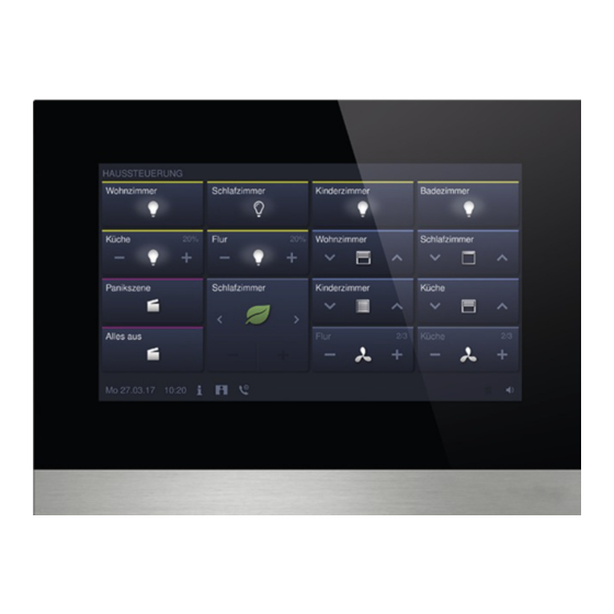
Application pages ■ Fig. 3: IP Touch 7 / IP touch 10 with control elements The main operating page is displayed after the device has started and is marked with a star in the navigation structure in the library area. - Page 21 Commissioning of the KNX Function via DCA (from ETS5) Navigation If you swipe to the right on the main operating page of the Busch IP touch, the configured application pages and basic settings are displayed in a menu. If you swipe to the left on the main operating page, the created operating pages are displayed. If several operating and application pages have been created on a level, you can call them up by swiping to the left or to the right.
-
Page 22: Commissioning Sequence
Commissioning of the KNX Function via DCA (from ETS5) Commissioning sequence To be able to work with the DCA commissioning tool as effectively as possible, the following work sequence (standard workflow) is recommended: 1. Start the ETS software (see chapter 1.2.1 “Starting the DCA“ on page 17). 2. -
Page 23: Basic Settings (System Settings) Of The Panel
Commissioning of the KNX Function via DCA (from ETS5) 1.6.1 Basic settings (system settings) of the panel Notice Entries in text fields must be confirmed with the return key. General Sending/receiving time and date ■ Options: No sending and no receiving Only sending Only receiving The device has an internal date and time module. - Page 24 Commissioning of the KNX Function via DCA (from ETS5) Lat. [dd.dd][+ = North, − = South] ■ Options: Setting option from +90.00 to -90.00 The parameter is used to set the geographic latitude for the location of the device (90° North to 90°...
- Page 25 Commissioning of the KNX Function via DCA (from ETS5) Temperature Notice The temperature parameters refer to the temperature display in the bottom bar of the display. In the "Basic KNX settings" it can be specified directly in the device that the temperature values are displayed in the bottom bar of the panel.
-
Page 26: Creation Of The Navigation Structure
Commissioning of the KNX Function via DCA (from ETS5) Creation of the navigation structure The panel contains operating pages (start pages) for operating the IP touch. These pages must be created beforehand. Generally a main start page is created (see chapter 1.4 “Explanation of the basic structure (Terms)“... -
Page 27: Editing Operating
Commissioning of the KNX Function via DCA (from ETS5) 1.7.2 Editing operating pages Adjust name of the page 1. Open the "Navigation" tab in the library area. 2. Select the operating page in the tree structure. 3. In the "Parameter" area, click in the name input field and enter a new name. The length of the name is limited to 60 characters. - Page 28 Commissioning of the KNX Function via DCA (from ETS5) Delete Page 1. In the tree structure, click on the page entry with the right mouse button. – A pop-up menu opens. 2. Click on "Delete". – The page is deleted with all entries. Notice The main operating page cannot be deleted.
-
Page 29: Configuration Of The Operating
Commissioning of the KNX Function via DCA (from ETS5) Configuration of the operating pages Control elements can be inserted into all operating pages (Start pages). Each control element can be pulled from the "Control elements" area via drag and drop onto the page view in the work area and pasted there. - Page 30 Commissioning of the KNX Function via DCA (from ETS5) Parameterising control elements 1. Open the "Navigation" tab in the library area. 2. Select a start or operating page in the tree structure. – The page is displayed in the work area. 3.
-
Page 31: Switch" Control Element
Commissioning of the KNX Function via DCA (from ETS5) 1.8.1 "Switch" control element You can, among others, set up a light control via the "Switch" control element. An allocated lamp can then be controlled via the control element. However, also an insert can be used as push-button or scene control element. -
Page 32: Control Element: "Value Slider
Commissioning of the KNX Function via DCA (from ETS5) 1.8.6 Control element: "Value slider" The values of a selected element (group address) can be displayed and at the same time adjusted via the slider using the "Value slider" control element. When adjusted, the values are displayed directly updated. -
Page 33: Page Link" Control Element
Commissioning of the KNX Function via DCA (from ETS5) 1.8.12 "Page link" control element The following links are possible via the "Page link" control element: on a page created directly via the commissioning tool (DCA) or ■ on the application pages "Door communication", "Alarm", "Timer" or "System settings". ■... -
Page 34: Editing Control Elements
Commissioning of the KNX Function via DCA (from ETS5) Editing control elements After the parameterization of the control elements, further editing can be carried out, e.g. a parameterized control element can be copied to additionally use it on a different operating page. Note All functions listed in the following can also be called up with the right mouse button. -
Page 35: Copy Control Element
Commissioning of the KNX Function via DCA (from ETS5) 1.9.2 Copy control element 1. Open the "Navigation" tab in the library area. 2. Select an operating page in the tree structure. – The page is displayed in the work area. 3. -
Page 36: Configuration Of Applications And Application
Commissioning of the KNX Function via DCA (from ETS5) 1.10 Configuration of applications and application pages The panel can contain applications with fixed functions (e.g. door communication). When these applications are activated, they can be accessed via the application pages or the application runs in the background. -
Page 37: Application "Fault And Alarm Messages
Commissioning of the KNX Function via DCA (from ETS5) 1.10.2 Application "Fault and alarm messages" This application has an application page on which the issued messages are displayed. The individual messages are also displayed directly in the panel according to the configuration. Messages can be created, activated and configured via the DCA. -
Page 38: Application "Scene Actuator
Commissioning of the KNX Function via DCA (from ETS5) 1.10.3 Application "Scene actuator" This application has no application page. The scene actuators are started via the "Scene" control element. The application serves for compiling a scene. The scene actuators can be created via the DCA. 1. -
Page 39: Application "Time Programs
Commissioning of the KNX Function via DCA (from ETS5) 1.10.5 Application "Time programs" This application has an application page, via which time programs can be set. This allows the holiday function to be started and set up, for example. The general settings can be made via the DCA. 1. -
Page 40: Application "Internal Rtc
Commissioning of the KNX Function via DCA (from ETS5) 1.10.7 Application "Internal RTC" This application has no application page. The internal RTC can be controlled via the "RTC control element" (extension unit). For this the control element must be allocated accordingly and equipped with group addresses. -
Page 41: Favourite Control Elements
Commissioning of the KNX Function via DCA (from ETS5) 1.10.8 "Favourite control elements" You can create favourites under "Favourite control elements" in the "Applications" tree structure. You can then use these favourite control elements repeatedly on other operating pages in the DCA. -
Page 42: Editing Communication Objects
Commissioning of the KNX Function via DCA (from ETS5) 1.11 Editing communication objects The available communication objects of the marked control elements (see work area) are listed in the "Communication objects" area. They can here be selected and edited directly via the ETS. -
Page 43: Editing Group Addresses
Commissioning of the KNX Function via DCA (from ETS5) 1.12 Editing group addresses Group addresses are created and managed in the "Group addresses" area. Notice Detailed expert knowledge for understanding by means of KNX training is assumed, especially with regard to the commissioning software ETS. Fig. -
Page 44: Additional Tools (Functions)
Commissioning of the KNX Function via DCA (from ETS5) 1.13 Additional tools (functions) You can call up additional tools or functions of the DCA via the DCA icon bar. 1.13.1 Import 1. Click on "Import" in the DCA toolbar, a dialog window with the following entries appears. –... -
Page 45: Export
Commissioning of the KNX Function via DCA (from ETS5) 1.13.2 Export 1. Click on "Export" in the DCA toolbar, a dialog window with the following entries appears. – Export image in pid file – Export in project file Export image in pid file This function is used to create an image file (*.pid). -
Page 46: Control Elements And Application Parameter
Control elements and application parameter "Switch" control element Control elements and application parameter "Switch" control element 2.1.1 Name of the control element Options: <Name> Naming the switch control element, e.g. name of the lamp that is to be switched. The length of the name is limited to 36 characters. 2.1.2 Function of the control element Options:... - Page 47 Control elements and application parameter "Switch" control element – Object type value 1: When actuated (pressing) the control element sends telegrams via the associated communication object. This parameter is used to specify the size of the communication object. – Object type value 2: When actuated (releasing) the control element sends telegrams via the associated communication object.
-
Page 48: Object Type 1 / Value 2
Control elements and application parameter "Switch" control element 2.1.5 Object type 1 / value 2 Options: Inactiv Switch Forced operation 1-byte value [0% - 100%] 1-byte value [0 - 255] 1-byte value [-128 - 127] Scene number RTC operating mode Temperature 2-byte value [-32768 - +32767] 2-byte value [0 - 65535]... - Page 49 Control elements and application parameter "Switch" control element Sent value 1 / value 2: Options: ON, forced operation active OFF, forced operation active Deactivate forced operation – 1-byte value [0% - 100%]: A value is sent as 1-byte value without a sign (percentage value). The following supplementary parameter is available: Sent value 1 / value 2 [0 - 100%]: Options:...
- Page 50 Control elements and application parameter "Switch" control element Transmitted value 1 / value 2 [temperature]: Options: Setting option from 16 - 31 – 2-byte value [-32768 - +32767]: A value is sent as 2-byte value with a sign, e.g. an actuating value or a time difference.
-
Page 51: Status Control Element (Icon/Text) Is Operated Via A Separate Object
Control elements and application parameter "Switch" control element 2.1.6 Status control element (icon/text) is operated via a separate object Options: An additional 1-bit communication object "Status" is enabled via the parameter. When the object has been enabled, the status display of the control element indicates the current status of the object. -
Page 52: Enable 1-Bit Communication Object "Disable
Control elements and application parameter "Switch" control element 2.1.8 Enable 1-bit communication object "Disable" Options: There is the option of temporarily disabling the function via an additional communication object "Disable". Product manual 2CKA001473B5023 │52... -
Page 53: Control Element "Rocker Switch
Control elements and application parameter Control element "Rocker switch" Control element "Rocker switch" 2.2.1 Name of the control element Options: <Name> Naming the switch control element, e.g. name of the lamp that is to be switched. The length of the name is limited to 36 characters. 2.2.2 Function of the control element Options:... -
Page 54: Icon Type
Control elements and application parameter Control element "Rocker switch" 2.2.4 Icon type Options: Icons text The parameter is used to set whether an icon or a text is displayed. – Icons: Icon for left / value 1: Options: <Selection of an icon from the list> The selected icon is displayed when the left rocker (button) is actuated. -
Page 55: Object Type
Control elements and application parameter Control element "Rocker switch" 2.2.6 Object type Options: Switch Forced operation 1-byte value [0% - 100%] 1-byte value [0 - 255] 1-byte value [-128 - 127] Scene number RTC operating mode Temperature 2-byte value [-32768 - +32767] 2-byte value [0 - 65535] 2-byte floating point 4-byte value [-2147483648 - 2147483647]... - Page 56 Control elements and application parameter Control element "Rocker switch" Sent value 1 / value 2 [0 - 255]: Options: Setting option from 0 - 255 – 1-byte value [-128 - 127]: A value is sent as 1-byte value with a sign, e.g. a actuating value. The following supplementary parameter is available: Sent value 1 / value 2 [-128 - 127]: Options:...
- Page 57 Control elements and application parameter Control element "Rocker switch" Sent value 1 / value 2 [-671088.64 - +670760.96]: Options: Setting option from -671088.64 - +670760.96 – 4-byte value [-2147483648 - 2147483647]: A value is sent as 4-byte value with a sign, e.g. an actuating value or a time difference.
-
Page 58: Enable 1-Bit Communication Object "Disable
Control elements and application parameter Control element "Rocker switch" 2.2.7 Enable 1-bit communication object "Disable" Options: There is the option of temporarily disabling the function via an additional communication object "Disable". Product manual 2CKA001473B5023 │58... -
Page 59: Dimmer" Control Element
Control elements and application parameter "Dimmer" control element "Dimmer" control element 2.3.1 Name of the control element Options: <Name> Naming the dimmer control element, e.g. name of the lamp that is to be dimmed. The length of the name is limited to 36 characters. 2.3.2 Function of the control element Options:... -
Page 60: Icon For On / Icon For Off
Control elements and application parameter "Dimmer" control element 2.3.5 Icon for On / icon for Off Options: Icon for On Icon for Off The parameter is used to set the icon that is to be displayed when the light is switched on or off. –... - Page 61 Control elements and application parameter "Dimmer" control element – No: No additional parameters available. – Yes: The brightness value signalled by the dimmer can be displayed via a separate object. An additional 1-bit communication object "Status value" is enabled. The displayed value does not originate from the control element.
-
Page 62: Manner Of Dimming
Control elements and application parameter "Dimmer" control element 2.3.10 Manner of dimming Options: Start/stop Stepwise Value – Start/stop: When the button is pressed a telegram with the information "dim brighter" or "dim darker" is sent. When the button is released a telegram with the information "top dimming" is sent. - Page 63 Control elements and application parameter "Dimmer" control element Options: Deactivated Activated There is the option of temporarily disabling the function via an additional communication object "Disable". Product manual 2CKA001473B5023 │63...
-
Page 64: Control Element: "Dimmer Slider
Control elements and application parameter Control element: "Dimmer slider" Control element: "Dimmer slider" 2.4.1 Name of the control element Options: <Name> Naming the slider control element, e.g. name of the lamp that is to be dimmed. The length of the name is limited to 36 characters. 2.4.2 Function of the control element Options:... -
Page 65: Icon For On / Icon For Off
Control elements and application parameter Control element: "Dimmer slider" 2.4.5 Icon for On / icon for Off Options: Icon for On Icon for Off The parameter is used to set the icon that is to be displayed when the light is switched on or off. –... -
Page 66: Display Value In Control Element
Control elements and application parameter Control element: "Dimmer slider" 2.4.8 Display value in control element Options: Deactivated Activated The parameter is used to specify whether the dimming value is displayed in the control element. – No: No display. No additional parameters available. –... -
Page 67: Slider Sends
Control elements and application parameter Control element: "Dimmer slider" 2.4.9 Slider sends Options: When releasing the slider Cyclic The parameter is used to specify whether the signal is sent "When releasing the slider" or "Cyclic". – When releasing the slider: No additional parameters available. –... -
Page 68: Operation Of "Rgbw" Control Element
Control elements and application parameter Operation of "RGBW" control element“ Operation of "RGBW" control element“ 2.5.1 Name of the control element Options: <Name> Naming the switch control element, e.g. name of the lamp that is to be switched. The length of the name is limited to 36 characters. 2.5.2 Function of the control element Options:... -
Page 69: Type Of Colour/White Lamp
Control elements and application parameter Operation of "RGBW" control element“ 2.5.4 Type of colour/white lamp Options: RGB+W RGB+WW/CW WW/CW The parameter is used to specify how the colour activation is to be controlled. Corresponding sliders will be displayed in the control element. The type of colour control depends on the type of lamp. - Page 70 Control elements and application parameter Operation of "RGBW" control element“ Switched On -> preset value: Options: Deactivated Activated – Deactivated: No presets are sent when the lamp is switched on. – Activated: The stored presets are sent when the lamp is switched on. Switched Off ->...
-
Page 71: Brightness Change [%]
Control elements and application parameter Operation of "RGBW" control element“ Switched Off -> RGB value 0,0,0: Options: Deactivated Activated – Deactivated: No RGB values are sent when the lamp is switched off. – Activated: The RGB values (0,0,0) are sent when the lamp is switched off. This parameter is important for lamps that do not contain a "Switch"... -
Page 72: Control Element: "Value Slider
Control elements and application parameter Control element: "Value slider" Control element: "Value slider" 2.6.1 Name of the control element Options: <Name> Naming the slider control element, e.g. name of the device that is to be controlled. The length of the name is limited to 36 characters. 2.6.2 Function of the control element Options:... -
Page 73: Display Value In Control Element
Control elements and application parameter Control element: "Value slider" 2.6.5 Display value in control element Options: Deactivated Activated The parameter is used to specify whether the value is displayed in the control element. – Deactivated: No display. No additional parameters available. –... -
Page 74: Object Type
Control elements and application parameter Control element: "Value slider" 2.6.7 Object type Options: 1-byte value [0% - 100%] 1-byte value [0 - 255] 1-byte value [-128 - 127] 2-byte value [0 - 65535] 2-byte value [-32768 - +32767] 2-byte floating point 4-byte value [0 - 4294967295] 4-byte value [-2147483648 - 2147483647] When actuated, the control element can send telegrams via the associated communication... -
Page 75: Enable 1-Bit Communication Object "Disable
Control elements and application parameter Control element: "Value slider" Maximum object value: Options: Setting option depends on the selected object type. The parameter is used to specify the largest value that is sent via telegrams. Any value within the limits specified by the object type and its value range can be entered. Displayed minimum value: Options: Setting option depends on the selected object type. -
Page 76: Blind" Control Element
Control elements and application parameter "Blind" control element "Blind" control element 2.7.1 Name of the control element Options: <Name> Naming the blind switch control element, e.g. name of the window whose blind is to be switched. The length of the name is limited to 36 characters. 2.7.2 Function of the control element Options:... -
Page 77: Type Of Control
Control elements and application parameter "Blind" control element 2.7.4 Type of control Options: Short = stepwise/stop, long = moving Short = moving/stop, long = stepwise Short = moving/stop The parameter is used to specify whether commands to move the blinds and adjust the slats are sent to linked blind actuators via short or long actuations of the the buttons. -
Page 78: Icon Type
Control elements and application parameter "Blind" control element 2.7.5 Icon type Options: Blind animation Shutter animation Marquee animation Hang animation User-defined The parameter is used to set whether a standard icon or a self-selected icon ("user-defined") is displayed. The following supplementary parameters are available for all options: Position for up/open icon: Options: Left... -
Page 79: Status Control Element (Icon) Is Operated Via A Separate Object
Control elements and application parameter "Blind" control element 2.7.6 Status control element (icon) is operated via a separate object Options: Deactivated Activated An additional 1-bit communication object "Switch status" is enabled via the parameter. – Deactivated: The communication object is not available. –... -
Page 80: Enable 1-Bit Communication Object "Disable
Control elements and application parameter "Blind" control element 2.7.7 Enable 1-bit communication object "Disable" Options: Deactivated Activated There is the option of temporarily disabling the function via an additional communication object "Disable". Product manual 2CKA001473B5023 │80... -
Page 81: Control Element "Fan Switch
Control elements and application parameter Control element "Fan switch" Control element "Fan switch" 2.8.1 Name of the control element Options: <Name> Naming the fan switch control element, e.g. name of the fan that is to be controlled. The length of the name is limited to 36 characters. 2.8.2 Function of the control element Options:... -
Page 82: Icon Type
Control elements and application parameter Control element "Fan switch" 2.8.5 Icon type Options: Default User-defined The parameter is used to set whether a standard icon or a self-selected icon ("user-defined") is displayed. The following supplementary parameters are available for all options: Position of the Up icon: Options: Left... -
Page 83: Number Of Levels
Control elements and application parameter Control element "Fan switch" 2.8.7 Number of levels Options: Setting option from 1 - 8 The parameter is used to specify the number of fan speed levels that are available and can be switched. 2.8.8 Object type Options: 1 bit [0/1]... - Page 84 Control elements and application parameter Control element "Fan switch" x of n (For 5 objects, object 1 to 5): 00000 > send all objects "0" 10000 > Object 1 sends "1" (also sends the 0 bit = Yes), objects 2 to 5 send "0" 11000 >...
-
Page 85: Display Status
Control elements and application parameter Control element "Fan switch" 2.8.9 Display status Options: User-defined Standard The parameter is used to specify which status texts are displayed for the individual switching levels. – User-defined: User-defined texts are displayed for the individual switching levels. The following supplementary parameters are available: Text Off: Options:... -
Page 86: Enable 1-Bit Communication Object "Disable
Control elements and application parameter Control element "Fan switch" 2.8.10 Enable 1-bit communication object "Disable" Options: Deactivated Activated There is the option of temporarily disabling the function via an additional communication object "Disable". Product manual 2CKA001473B5023 │86... -
Page 87: Scene" Control Element
Control elements and application parameter "Scene" control element "Scene" control element 2.9.1 Name of the control element Options: <Name> Naming of the scene control element. The length of the name is limited to 36 characters. 2.9.2 Function of the control element Options: Not defined (grey) Light (yellow) -
Page 88: Scene Number X [1 - 64]
Control elements and application parameter "Scene" control element 2.9.6 Scene number x [1 - 64] Options: Setting option from 1 - 64 The parameter is used to specify which scenes are to be started. Notice How many "Scene number x [1 - 64]" parameters are available depends on the setting of the "Number of scenes [1 - 10]"... -
Page 89: Display" Control Element
Control elements and application parameter "Display" control element 2.10 "Display" control element 2.10.1 Name of the control element Options: <Name> Naming of the display control element. The length of the name is limited to 36 characters. 2.10.2 Function of the control element Options: Not defined (grey) Light (yellow) -
Page 90: Type Of Display Element - Status Display - Size Of The Button
Control elements and application parameter "Display" control element – Rain: The rain values of an allocated element are displayed. – Twilight: The twilight values of an allocated element are displayed. – Brightness: The brightness values of an allocated element are displayed. –... -
Page 91: Type Of Display Element - Value Display - Size Of The Button
Control elements and application parameter "Display" control element Text x for value [0 - 255]: Options: Setting option from 0 - 255 The parameter is used to set the status value at which text x is displayed. Notice 8 parameters "Text x at value [0 - 255]" are available which can be set as required. -
Page 92: Type Of Display Element - Value Display - Object Type
Control elements and application parameter "Display" control element 2.10.7 Type of display element — Value display — Object type Options: 1-byte value [0% - 100%] 1-byte value [0 - 255] 1-byte value [-128 - 127] 2-byte value [0 - 65535] 2-byte value [-32768 - +32767] 2-byte floating point 4-byte value [0 - 4294967295]... -
Page 93: Type Of Display Element - Linear Measurement Display - Measurement Display With Colour Display
Control elements and application parameter "Display" control element Decimal places: Options: Setting option from 0 - 2 The parameter is used to specify the number of decimal places of the displayed value. The number is limited to 2 places. Thousands separator: Options: Deactivated Activated... -
Page 94: Type Of Display Element - Linear Measurement Display - Display Value In Control Element
Control elements and application parameter "Display" control element 2.10.9 Type of display element — Linear measurement display — Display value in control element Options: Deactivated Activated The parameter is used to specify whether the value of the selected element is displayed in the display element. -
Page 95: Type Of Display Element - Linear Measurement Display - Object Type
Control elements and application parameter "Display" control element 2.10.10 Type of display element — Linear measurement display — Object type Options: 1-byte value [0% - 100%] 1-byte value [0 - 255] 1-byte value [-128 - 127] 2-byte value [0 - 65535] 2-byte value [-32768 - +32767] 2-byte floating point 4-byte value [0 - 4294967295]... -
Page 96: Type Of Display Element - Round Measurement Display
Control elements and application parameter "Display" control element Minimum object value: Options: Setting option depends on the selected object type. The parameter is used to specify the smallest value that is sent via telegrams to the display element. Any value within the limits specified by the object type and its value range can be entered. Maximum object value: Options: Setting option depends on the selected object type. -
Page 97: Type Of Display Element - Wind Rose
Control elements and application parameter "Display" control element 2.10.12 Type of display element — Wind rose Note For option "Wind rose" of parameter "Type of display element" the same supplementary parameters are available, such as for option "Linear measurement display", see chapter 2.10.8 “Type of display element — Linear measurement display —... -
Page 98: Type Of Display Element - Wind Force - Unit
Control elements and application parameter "Display" control element 2.10.14 Type of display element — Wind force — Unit Options: km/h The parameter is used to specify the unit with which the wind force is displayed in the display element. 2.10.15 Type of display element — Temperature — Size of the button Options: 1 column 2 columns... -
Page 99: Type Of Display Element - Rain - Text For No Rain
Control elements and application parameter "Display" control element 2.10.19 Type of display element — Rain — Text for no rain Options: <Text> The parameter is used to specify the text that is displayed for dry weather. The length of the text is limited to 60 characters. 2.10.20 Type of display element —... -
Page 100: Type Of Display Element - Moisture - Unit
Control elements and application parameter "Display" control element The parameter is used to specify whether the display element occupies one column (one button or control frame) or two columns (two buttons or control frames). 2.10.26 Type of display element — Moisture — Unit Options: Fixed at % The parameter is used to specify the unit with which the air moisture is displayed in the display... -
Page 101: Control Element "Rtc Control Element
Control elements and application parameter Control element "RTC control element" 2.11 Control element "RTC control element" 2.11.1 Name of the control element Options: <Name> Naming of the RTC control element. The length of the name is limited to 36 characters. 2.11.2 Function of the control element Options:... -
Page 102: Input For Temperature Reading
Control elements and application parameter Control element "RTC control element" 2.11.5 Input for temperature reading Options: Internal measurement External measurement The parameter is used to specify whether the temperature is read via an internal or external temperature sensor. – Internal measurement: The following supplementary parameters are available: Cyclic sending of the current actual temperature [min.]: Options: Setting option from 5 - 240... -
Page 103: Unit Of Temperature
Control elements and application parameter Control element "RTC control element" 2.11.7 Unit of temperature Options: °C °F The parameter is used to specify the unit with which the temperature is displayed. 2.11.8 Set value is relative Options: The parameter is used to specify whether the set value for devices with display is displayed as relative value, e.g. - Page 104 Control elements and application parameter Control element "RTC control element" There is the option of temporarily disabling the function via an additional communication object "Disable". Product manual 2CKA001473B5023 │104...
-
Page 105: Page Link" Control Element
Control elements and application parameter "Page link" control element 2.12 "Page link" control element 2.12.1 Name of the control element Options: <Name> Naming of the page link control element. The length of the name is limited to 36 characters. 2.12.2 Function of the control element Options: Not defined (grey) -
Page 106: Enable 1-Bit Communication Object "Disable
Control elements and application parameter "Page link" control element 2.12.5 Enable 1-bit communication object "Disable" Options: Deactivated Activated There is the option of temporarily disabling the function via an additional communication object "Disable". Product manual 2CKA001473B5023 │106... -
Page 107: Control Element "Audio Control
Control elements and application parameter Control element "Audio control" 2.13 Control element "Audio control" 2.13.1 Name of the control element Options: <Name> Naming of the control element for audio control. The length of the name is limited to 36 characters. 2.13.2 Function of the control element Options:... -
Page 108: Use Of Play Button
Control elements and application parameter Control element "Audio control" 2.13.4 Use of play button Options: Deactivated Activated – Deactivated: No playback button is enabled. No additional parameters available. – Activated: The playback button is enabled. The following supplementary parameter is available: Object type play button: Options:... -
Page 109: Use Of Stop Button
Control elements and application parameter Control element "Audio control" Value for pause: Options: The parameter is used to send the command of the pause button with "0" or "1". 1-byte value [0 - 255]: The value of a pause button is sent as 1-byte value without a sign. -
Page 110: Use Of Forward Button
Control elements and application parameter Control element "Audio control" 2.13.7 Use of forward button Options: Deactivated Activated – Deactivated: No forward button is enabled. No additional parameters available. – Activated: The forward button is enabled. The following supplementary parameter is available: Object type forward button: Options:... -
Page 111: Use Of Return Key
Control elements and application parameter Control element "Audio control" 2.13.8 Use of return key Options: Deactivated Activated – Deactivated: No backspace key is enabled. No additional parameters available. – Activated: The backspace key is enabled. The following supplementary parameter is available: Object type backspace key: Options:... -
Page 112: Use Of Button For Mute
Control elements and application parameter Control element "Audio control" 2.13.9 Use of button for mute Options: Deactivated Activated – Deactivated: No mute button is enabled. No additional parameters available. – Activated: The mute button is enabled. The following supplementary parameter is available: Object type mute: Options: 1 bit... -
Page 113: Use Of Volume Button
Control elements and application parameter Control element "Audio control" 2.13.10 Use of volume button Options: Deactivated Activated – Deactivated: No volume button is enabled. No additional parameters available. – Activated: The volume button is enabled. The following supplementary parameter is available: Object type volume button: Options:... -
Page 114: Use Of On/Off Button
Control elements and application parameter Control element "Audio control" 2.13.11 Use of ON/OFF button Options: Deactivated Activated – Deactivated: No ON/OFF button is enabled. No additional parameters available. – Activated: The ON/OFF button is enabled. The following supplementary parameter is available: Object type ON/OFF button: Options:... -
Page 115: Application "Door Communication
Control elements and application parameter Application "Door communication" 2.14 Application "Door communication" 2.14.1 Use of door communication Options: The parameter is used to specify whether an application page is displayed in the panel for the door communication. – No: No application page is displayed. No additional parameters available. –... -
Page 116: Speech Volume Preset [%]
Control elements and application parameter Application "Fault and alarm messages" - Global settings 2.14.4 Speech volume preset [%] Options: Setting option from 10 - 100 Preset of speech volume in percent. 2.15 Application "Fault and alarm messages" - Global settings 2.15.1 Use of fault and alarm messages Options:... -
Page 117: Enable Export
Control elements and application parameter Application "Fault and alarm messages" - Global settings 2.15.3 Enable export Options: Deactivated Activated The parameter is used to specify whether the messages can be exported under the fixed file name in CSV format. The messages can then be exported via the application page. –... -
Page 118: Sound For Notice
Control elements and application parameter Application "Fault and alarm messages" - Global settings 2.15.6 Sound for Notice Options: Setting option from 1 - 5 The parameter is used to specify which signal tone is to be played during the display of the message. -
Page 119: Application "Fault And Alarm Messages" - Settings Of The Individual Messages
Control elements and application parameter Application "Fault and alarm messages" - Settings of the individual messages 2.16 Application "Fault and alarm messages" - Settings of the individual messages 2.16.1 Name of message Options: <Name> Designation of message. The length of the name is limited to 60 characters. 2.16.2 Type of message Options:... - Page 120 Control elements and application parameter Application "Fault and alarm messages" - Settings of the individual messages Repeat of alarm as long as it is active: Options: Deactivated Activated – Deactivated: In the active state the acoustic alarm signal is not repeated. No additional parameters available.
-
Page 121: Application "Scene Actuator
Control elements and application parameter Application "Scene actuator" 2.17 Application "Scene actuator" 2.17.1 Name of scene actuator Options: <Text> Naming of scene actuator. The length of the name is limited to 60 characters. 2.17.2 Number of participants Options: Setting options from 1 - 15 The parameter is used to specify the number of participants (actuators). -
Page 122: Object Type X
Control elements and application parameter Application "Scene actuator" 2.17.6 Object type x Options: Switch Roller blind Forced operation 1-byte value [0 - 100%] 1-byte value [0 - 255] RGB colour 8-bit scene RTC operating mode Temperature 14-byte text When actuated or during a sequence, components of a scene can send telegrams via the associated communication object. - Page 123 Control elements and application parameter Application "Scene actuator" Value for object x: Options: Setting option from 0 - 100 – 1-byte value [0 - 255]: A value is sent as 1-byte value without a sign, e.g. actuating value, angle or brightness value. The following supplementary parameter is available: Value for object x: Options: Setting option from 0 - 255...
-
Page 124: Name Of Scene
Control elements and application parameter Application "Scene actuator" 2.17.7 Name of scene Options: <Text> Designation of scene. The length of the name is limited to 60 characters. 2.17.8 Scene number Options: Setting option from 1 - 64 The number of the scene is set via the parameter. 2.17.9 Light scenes can be started with Options:... -
Page 125: Application "Presence Simulation
Control elements and application parameter Application "Presence simulation" 2.18 Application "Presence simulation" 2.18.1 Use of presence simulation Options: Deactivated Activated The parameter is used to specify whether presence simulation is displayed. – Disabled: No display in the panel. No additional parameters available. –... -
Page 126: Enable Export
Control elements and application parameter Application "Presence simulation" 2.18.3 Enable export Options: Deactivated Activated The parameter is used to specify that the recorded telegrams can be exported under the fixed file name in CSV format. – Deactivated: No export. No additional parameters available. –... -
Page 127: Application "Time Programs
Control elements and application parameter Application "Time programs" 2.19 Application "Time programs" 2.19.1 Page PIN-protected Options: The parameter is used to specify whether the time programs application page is protected by a PIN code. – No: The application page is not protected. –... -
Page 128: Application "Logical Functions
Control elements and application parameter Application "Logical functions" 2.20 Application "Logical functions" 2.20.1 Channel x — Application Options: Inactive Logic gate Multiplexer Multiplier Gate Temperature comparator Status converter Time function The parameter is used to specify the logic function that is allocated to channel x. Depending on the selection, individual parameters appear for the respective logic function. - Page 129 Control elements and application parameter Application "Logical functions" Options: 1 bit 1 byte The parameter is used to specify whether the input object consists of a 1-bit value (0/1) or a 1-byte value (0 - 255). See the explanation above. Notice How many "Object type input x"...
- Page 130 Control elements and application parameter Application "Logical functions" Value of the output object at logic untrue: Options: Output is set on 0 Defined via output default value untrue The parameter is used to specify the value of the output object in the logic status "Untrue". See the explanation above.
- Page 131 Control elements and application parameter Application "Logical functions" See the explanation above. – 1 bit: The following parameter appears: Start command: Options: OFF - telegram ON - telegram See the explanation above. – 1 byte: The following parameter appears: Start command: Options: Setting options from 0 - 255 See the explanation above.
- Page 132 Control elements and application parameter Application "Logical functions" Value of output x: Options: Setting options from 0 - 100 This parameter is used to specify the value (in percent) the communication object has on output x. Notice How many "Value of output x" parameters are displayed depends on the setting of the "Outputs used"...
- Page 133 Control elements and application parameter Application "Logical functions" Object type input/output: Options: Switch Forced operation 1-byte value [0% - 100%] 1-byte value [0 - 255] 1-byte value [-128 - 127] Scene number RTC operating mode Temperature 2-byte value [-32768 - +32767] 2-byte value [0 - 65535] 2-byte floating point 4-byte value [-2147483648 - 2147483647]...
- Page 134 Control elements and application parameter Application "Logical functions" – 2-byte value [0 - 65535]: A value is sent as 2-byte value without a sign, e.g. actuating value or time interval. No additional parameters available. – 2-byte floating point: A value is sent as 2-byte floating point value, e.g. a temperature value, a time duration, a performance or a consumption value.
- Page 135 Control elements and application parameter Application "Logical functions" Object type of the output: Options: 1 bit 1 byte The parameter is used to specify whether the output object sends a 1-bit value (0/1) or a 1- byte value (0 - 255). –...
- Page 136 Control elements and application parameter Application "Logical functions" Cycle time: Options: Setting options from 00:00:01 - 00:30:00 The parameter is used to specify the cycle time (hh:mm:ss). – Status converter: This function is used to convert an input value into a 14-byte text or divide it into several 1-bit telegrams.
- Page 137 Control elements and application parameter Application "Logical functions" Text x for value [0 - 255]: Options: Setting options from 0 - 255 The parameter is used to set which value is to be converted into text x. Text x: Options: <Text>...
- Page 138 Control elements and application parameter Application "Logical functions" Staircase light period [hh:mm:ss]: Options: Setting options from 00:00:01 - 12:00:00 The time of the switch-off delay (hh:mm:ss) is set via the parameter. Use of switch-on delay time: Options: Deactivated Activated The parameter is used to specify whether the staircase light is switched with a switch-on delay.
-
Page 139: Application "Internal Rtc
Control elements and application parameter Application "Internal RTC" 2.21 Application "Internal RTC" 2.21.1 General — Device function Options: Single device Master device Temperature transmitter – Single device: The device is used individually in a room for temperature control with fixed temperature values. -
Page 140: General - Operating Mode After Reset
Control elements and application parameter Application "Internal RTC" – Heating and cooling: For operating a two-wire or four-wire system used to heat or cool a room. Switching between heating and cooling takes place using a central switch (two-wire system) or is carried out manually and / or automatically via the single room temperature controller (four-wire system). -
Page 141: General - Send Cyclic "In Operation" (Min)
Control elements and application parameter Application "Internal RTC" 2.21.4 General — Send cyclic "In operation" (min) Options: Setting option between 5 - 3000 minutes – Communication object "In operation" serves for the information that the controller still operates. Value "1" is sent cyclic. The cycle for sending is set via this parameter. If there is no cyclic telegram, the function of the device is disturbed and the air-conditioning of the room can be maintained via forced control. -
Page 142: Heating Control - Control Value Type
Control elements and application parameter Application "Internal RTC" 2.21.7 Heating control — Control value type Options: 2-point 1 bit, Off/On 2-point 1 byte, (0/100%) PI continuous, 0-100% PI PWM, On/Off Fan coil The actuation of the control valve is determined by the selection of the controller type. –... -
Page 143: Heating Control - Heating Type
Control elements and application parameter Application "Internal RTC" 2.21.8 Heating control — Heating type Optionen: PI continuous, 0 – 100% and PI PWM, On/Off: Area (e.g. floor heating) 4°C 200 min ■ Convector (e.g. heater) 1.5°C 100 min ■ Free configuration ■... -
Page 144: Heating Control - I-Component (Min.)
Control elements and application parameter Application "Internal RTC" 2.21.10 Heating control — I-component (min.) Options: Setting option between 0 - 255 The I-component refers to the reset time of a control. The integral component has the effect of moving the room temperature slowly toward, and ultimately reaching, the setpoint value. Depending on the type of system used, the reset time has to have different values. -
Page 145: Basic Stage Heating - Hysteresis (X 0.1°C)
Control elements and application parameter Application "Internal RTC" 2.21.15 Basic stage heating — Hysteresis (x 0.1°C) Options: Setting option between 3 - 255 The hysteresis of the two-point controller specifies the fluctuation range of the controller around the setpoint value. The lower switching point is located at "Setpoint value minus hysteresis" and the upper point is at "Setpoint value plus hysteresis". -
Page 146: Basic Stage Heating - Pwm Cycle Heating (Min)
Control elements and application parameter Application "Internal RTC" 2.21.18 Basic stage heating — PWM cycle heating (min) Options: Setting option between 1 - 60 minutes In PI PWM, On/off the control value percentage values are converted into a pulse-interval signal. This means that a selected PWM cycle will be divided into an on-phase and an off-phase based on the control value. -
Page 147: Settings Of Basic Load - Minimum Control Value For Basic Load > 0
Control elements and application parameter Application "Internal RTC" 2.21.21 Settings of basic load — Minimum control value for basic load > 0 Options: Always active Activate via object The function finds application when in the desired area, e.g. with floor heating, the floor is to have a basic warmth. -
Page 148: Setpoint Settings - Setpoint Temperature For Heating Comfort (°C)
Control elements and application parameter Application "Internal RTC" 2.21.23 Setpoint settings — Setpoint temperature for heating comfort (°C) Options: Setting option between 10 - 40 Specifies the comfort temperature for heating when people are present. Note This parameter is only available when the "Control function" parameter is set on "Heating, "Heating with additional stage", "Heating and cooling"... -
Page 149: Setpoint Settings - Set-Point Temperature For Frost Protection (°C)
Control elements and application parameter Application "Internal RTC" 2.21.26 Setpoint settings — Set-point temperature for frost protection (°C) Options: Setting option between 5 - 15 Function for protecting the building against the cold. On devices with a display, this mode is indicated by the frost protection icon. -
Page 150: Setpoint Adjustment - Maximum Manual Reduction During Heating Mode (0 - 9°C)
Control elements and application parameter Application "Internal RTC" 2.21.30 Setpoint adjustment — Maximum manual reduction during heating mode (0 - 9°C) Options: Setting option between 0 - 9 This preset can be used to limit the manual decrease during heating. Note This parameter is only available when parameter "Controller function"... -
Page 151: Setpoint Adjustment - Resetting The Manual Adjustment Via Object
Control elements and application parameter Application "Internal RTC" 2.21.33 Setpoint adjustment — Resetting the manual adjustment via object Options: Deactivated Activated If this parameter is activated, a separate object can be used to delete the manual adjustment at any time. Example of application: Resetting the manual adjustment on all devices located in an office building using a system clock. -
Page 152: Temperature Reading - Weighting Of Internal Measurement (0 To 100%)
Control elements and application parameter Application "Internal RTC" 2.21.37 Temperature reading — Weighting of internal measurement (0 to 100%) Options: Setting option between 0 - 100 Specifying the weighting of the internal measurement from 0 to 100%. Note This parameter is only available when the "Inputs of weighted temperature reading"... -
Page 153: Temperature Reading - Difference Of Value For Sending The Actual Temperature (X 0.1°C)
Control elements and application parameter Application "Internal RTC" 2.21.41 Temperature reading — Difference of value for sending the actual temperature (x 0.1°C) Options: Setting option between 1 - 100 If the change in temperature exceeds the parameterised difference between the measured actual temperature and the previous actual temperature that was sent, the changed value will be transmitted. -
Page 154: Temperature Reading - Control Value For Fault (0 - 255)
Control elements and application parameter Application "Internal RTC" 2.21.44 Temperature reading — Control value for fault (0 - 255) Options: Setting option between 0 - 255 In the event of a failure of the actual temperature measurement, the device will no longer be able to independently determine the control value. -
Page 155: Control Of Additional Heating Stage - Additional Heating Type
Control elements and application parameter Application "Internal RTC" 2.21.48 Control of additional heating stage — Additional heating type Options: PI continuous, 0 – 100% and PI PWM, On/Off: Area (e.g. floor heating) 4°C 200 min ■ Convector (e.g. heater) 1.5°C 100 min ■... -
Page 156: Control Of Additional Heating Stage - I-Component (Min)
Control elements and application parameter Application "Internal RTC" 2.21.50 Control of additional heating stage — I-component (min) Options: Setting option between 0 - 255 The I-component refers to the reset time of a control. The integral component has the effect of moving the room temperature slowly toward, and ultimately reaching, the setpoint value. -
Page 157: Cooling Control - P-Component (X 0.1°C)
Control elements and application parameter Application "Internal RTC" 2.21.52 Cooling control — P-component (x 0.1°C) Options: Setting option between 10 - 100 The P-component refers to the proportional band of a control. It fluctuates around the setpoint value and can be used to influence control speed with a PI controller. The smaller the setpoint, the faster it reacts to the control. -
Page 158: Basic Stage Cooling
Control elements and application parameter Application "Internal RTC" 2.21.55 Basic stage cooling Note Only available when the "Extended settings" parameter under "Cooling control" is set on "Yes". 2.21.56 Basic stage cooling — Status object cooling Options: Deactivated Activated This parameter enables the "Status cooling" communication object. 2.21.57 Basic stage cooling —... -
Page 159: Basic Stage Cooling - Hysteresis (X 0.1°C)
Control elements and application parameter Application "Internal RTC" 2.21.58 Basic stage cooling — Hysteresis (x 0.1°C) Options: Setting option between 3 - 255 The hysteresis of the two-point controller specifies the fluctuation range of the controller around the setpoint value. The lower switching point is located at "Setpoint value minus hysteresis" and the upper point is at "Setpoint value plus hysteresis". -
Page 160: Basic Stage Cooling - Pwm Cycle Cooling (Min)
Control elements and application parameter Application "Internal RTC" 2.21.60 Basic stage cooling - PWM cycle cooling (min) Options: Setting option between 1 - 60 minutes In PI PWM, On/off the control value percentage values are converted into a pulse-interval signal. This means that a selected PWM cycle will be divided into an on-phase and an off-phase based on the control value. -
Page 161: Settings Of Basic Load - Minimum Control Value For Basic Load > 0
Control elements and application parameter Application "Internal RTC" 2.21.63 Settings of basic load — Minimum control value for basic load > 0 Options: Always active Activate via object The function finds application when in the desired area, e.g. with floor heating, the floor is to have a basic warmth. -
Page 162: Setpoint Settings - Setpoint Temperature For Cooling Comfort (°C)
Control elements and application parameter Application "Internal RTC" 2.21.65 Setpoint settings — Setpoint temperature for cooling comfort (°C) Options: Setting option between 10 - 40 Specifies the comfort temperature for cooling when people are present. Note This parameter is only available when the "Control function" parameter is set on "Cooling"... -
Page 163: Setpoint Settings - Set-Point Temperature For Heat Protection (°C)
Control elements and application parameter Application "Internal RTC" 2.21.68 Setpoint settings — Set-point temperature for heat protection (°C) Options: Setting option between 27 - 45 Function for protecting the building against heat. On devices with a display, this mode is indicated by the heat protection icon. -
Page 164: Setpoint Adjustment - Maximum Manual Reduction During Cooling Mode (0 - 9°C)
Control elements and application parameter Application "Internal RTC" 2.21.72 Setpoint adjustment — Maximum manual reduction during cooling mode (0 - 9°C) Options: Setting option between 0 - 9 This preset can be used to limit the manual decrease during cooling. Note This parameter is only available when the "Control function"... -
Page 165: Setpoint Adjustment - Resetting The Manual Adjustment Via Object
Control elements and application parameter Application "Internal RTC" 2.21.75 Setpoint adjustment — Resetting the manual adjustment via object Options: Deactivated Activated If this parameter is activated, a separate object can be used to delete the manual adjustment at any time. Example of application: Resetting the manual adjustment on all devices located in an office building using a system clock. -
Page 166: Temperature Reading - Inputs Of Weighted Temperature Reading
Control elements and application parameter Application "Internal RTC" 2.21.79 Temperature reading — Inputs of weighted temperature reading Options: Internal and external measurement 2 x external measurement Internal and 2x external measurement Specifies the temperature reading inputs for the weighted measurement, in which the calculated weighted average of the inputs is used as an input value for control Note This parameter is only available when the "Inputs of temperature reading"... -
Page 167: Temperature Reading - Difference Of Value For Sending The Actual Temperature (X 0.1°C)
Control elements and application parameter Application "Internal RTC" The current actual temperature used by the device can be cyclically transmitted to the bus. 2.21.84 Temperature reading — Difference of value for sending the actual temperature (x 0.1°C) Options: Setting option between 1 - 100 If the change in temperature exceeds the parameterised difference between the measured actual temperature and the previous actual temperature that was sent, the changed value will be transmitted. -
Page 168: Temperature Reading - Monitoring Time For Temperature Reading (0 = No Monitoring) (Min)
Control elements and application parameter Application "Internal RTC" 2.21.86 Temperature reading — Monitoring time for temperature reading (0 = no monitoring) (min) Options: Setting option between 0 - 120 If no temperature is read within the parameterized time period, the device switches to error mode. -
Page 169: Alarm Functions - Dew Point Alarm
Control elements and application parameter Application "Internal RTC" 2.21.89 Alarm functions — Dew point alarm Options: Deactivated Activated When refrigerating machines are used, dew may appear on the refrigerant supply lines during operation as a result of excessive cooling and/or humidity. The dew indicator signals the dew formation via the "Dew point alarm"... -
Page 170: Summer Compensation - Summer Compensation
Control elements and application parameter Application "Internal RTC" 2.21.93 Summer compensation — Summer compensation Options: In order to save energy, and to ensure that the temperature difference occurring during entry and exit of a climate-controlled building stays within comfortable limits, the excessive reduction of room temperature should be prevented during high temperatures in the summer ( Summer compensation according to DIN 1946). -
Page 171: Summer Compensation -- (Lower) Starting Temperature For Summer Compensation (°C)
Control elements and application parameter Application "Internal RTC" 2.21.94 Summer compensation -— (Lower) Starting temperature for summer compensation (°C) Options: Setting option between -127 - 127 The parameter defines the lower outside temperature value up to which temperature value the setpoint correction (summer compensation) is performed based on too high an outside temperature. -
Page 172: Summer Compensation - Offset Of The Set-Point Temperature For The Exit From Summer Compensation (X 0.1°C)
Control elements and application parameter Application "Internal RTC" 2.21.97 Summer compensation — Offset of the set-point temperature for the exit from summer compensation (x 0.1°C) Options: Setting option between -127 - 127 The parameter is used to define how many degrees Kelvin the setpoint value will be increased by during summer compensation when the upper temperature value is reached. -
Page 173: Control Of Additional Cooling Stage - Cooling Type
Control elements and application parameter Application "Internal RTC" 2.21.98 Control of additional cooling stage — Cooling type Options: PI continuous, 0 – 100% and PI PWM, On/Off: Area (e.g. cooling ceiling) 5°C 240 min ■ Free configuration ■ Fan coil: Fan coil 4°C 90 min ■... -
Page 174: Control Of Additional Cooling Stage - P-Component (Min)
Control elements and application parameter Application "Internal RTC" 2.21.100 Control of additional cooling stage — P-component (min) Options: Setting option between 0 - 255 The I-component refers to the reset time of a control. The integral component has the effect of moving the room temperature slowly toward, and to ultimately reaching, the setpoint. -
Page 175: Combined Heating And Cooling Modes - Operating Mode After Reset
Control elements and application parameter Application "Internal RTC" 2.21.103 Combined heating and cooling modes — Operating mode after reset Options: Cooling Heating After a bus voltage failure, a system reset, or the attachment of a device to the bus coupler, the device starts in the parameterized "Operating mode after reset". -
Page 176: Setpoint Settings - Hysteresis For Switchover Heating/Cooling (X 0.1°C)
Control elements and application parameter Application "Internal RTC" 2.21.106 Setpoint settings — Hysteresis for switchover heating/cooling (x 0.1°C) Options: Setting option between 5 - 100 This parameter specifies the one-sided hysteresis for switching between heating and cooling when "Setpoint heating comfort = Setpoint cooling comfort" is active. If the room temperature exceeds the setpoint temperature value plus hysteresis, the system switches to cooling. -
Page 177: Combined Heating And Cooling Modes - Additional Heating/Cooling Stage Control Value Output
Control elements and application parameter Application "Internal RTC" 2.21.109 Combined heating and cooling modes — Additional heating/cooling stage control value output Options: Via 1 object Via 2 objects This parameter is used to define whether the control value is transmitted to the climate control actuator using one or two objects. -
Page 178: Communication Objects
Um einen schnellen Überblick über die Funktionsmöglichkeit des Dimmers zu erhalten, sind alle Kommunikationsobjekte in einer Übersichtstabelle aufgeführt. Die detaillierte Funktion kann in der anschließenden Beschreibung der einzelnen Kommunikationsobjekte nachgelesen werden. For a quick overview of the options of the ABB RoomTouch ®... - Page 179 Communication objects Application "Internal RTC" bright (dark = 1) Switching [5.001] Signal tone volume Input 1 byte Percent (0 - 100%) [1.001] Confirm all [1 bit] Input 1 bit Switching [5.001] Heating control value Output 1 bit Percent (0 - 100%) [5.001] Additional heating stage Output...
- Page 180 Communication objects Application "Internal RTC" (master) Percent (0 - 100%) Input/ [16.001] Value 1 [send] 1 byte Output Scene control [16.001] Value 2 [send] Output 1 byte Percent (0 - 100%) [16.001] Input/ Value 1 byte Percent Output (0 - 100%) [5.001] Percent Status value...
- Page 181 Communication objects Application "Internal RTC" Output Counting pulses (0 - 255) [5.010] Input/ Counting Value green 1 byte Output pulses (0 - 255) [5.010] Input/ Counting Value blue 1 byte Output pulses (0 - 255) [232.600] Input/ Value RGB [3 bytes] 3 bytes RGB value 3x Output...
- Page 182 Communication objects Application "Internal RTC" [1.002] Output 8 (MSB) Output 1 bit Boolean Input/ [1.002] Output 9 1 bit Output Boolean Input/ [1.002] Output 10 1 bit Output Boolean Input/ [1.002] Output 11 1 bit Output Boolean Input/ [1.002] Output 12 1 bit Output Boolean...
- Page 183 Communication objects Application "Internal RTC" [16.001] Object 1 [receive] Input 14 bytes Counting pulses [232.600] Object 2 [send] Output 3 bytes Colour RGB [232.600] Object 2 [receive] Input 3 bytes Colour RGB [232.600] Object 3 [send] Output 3 bytes Colour RGB [232.600] Object 3 [receive] Input...
- Page 184 Communication objects Application "Internal RTC" [232.600] Object 14 [receive] Input 3 bytes Colour RGB [232.600] Object 15 [send] Output 3 bytes Colour RGB [232.600] Object 15 [receive] Input 3 bytes Colour RGB [1.010] Activate scene x Input 1 bit Start [3.007] Dimming scene x Input...
- Page 185 Communication objects Application "Internal RTC" Fan coil manual confirmation [1.001] Output 1 bit (Master) Switching Fan coil manual confirmation Input/ [1.001] 1 bit (Slave) Output Switching Request fan speed level [5.010] Output 1 bit manually (slave) Switching Request fan speed level [1.001] Input 1 bit...
- Page 186 Communication objects Application "Internal RTC" [9.001] Limit temperature additional Input 2 bytes Temperature heating stage (°C) [9.001] Limit temperature basic Input 2 bytes Temperature cooling stage (°C) [9.001] Limit temperature additional Input 2 bytes Temperature cooling stage (°C) Fan manual (cooling) [1.001] Output 1 bit...
- Page 187 Communication objects Application "Internal RTC" [16.001] Input/ Counting Message 14 bytes Output pulses (-128 - 127) [16.001] Acknowledge message Counting Output 14 bytes [14 bytes] pulses (-128 - 127) Acknowledge message Input/ [16.016] 1 bit [1 bit] Output Acknowledge [20.102] Input/ Operating mode 1 byte...
- Page 188 Communication objects Application "Internal RTC" Counting pulses (0 - 255) [16.001] Counting Information page line 2 Input 14 bytes pulses (0 - 255) [16.001] Counting Information page line 3 Input 14 bytes pulses (0 - 255) [16.001] Information page line 4 Input 14 bytes Counting...
-
Page 189: Operation
Operation Operation General control and display functions After the device has been connected to the power supply, the boot-up process starts. Then the parameterized main control page (homepage) is displayed. This is marked with a star in the page display. Fig. - Page 190 Operation [1] Floors/rooms navigation – When parameterized, this can be used to call up the operating pages which have been allocated to the floors/rooms. [2] Touch-sensitive user interface – For the IP touch up to 16 or 25 KNX functions can be positioned one one operating page.
-
Page 191: Control Elements
Operation Control elements Control elements in the IP touch are used for fulfilling the basic functions of "Switching", "Dimming", "Blind", "Scenes" and "RTC". The elements can contain switches, buttons and sliders. Available are: Button operation Execution of function with a single press Tapping operation Execution of function by pressing and holding Control operation... -
Page 192: Basic Structures Of Control Elements
Operation 4.2.1 Basic structures of control elements Fig. 8: Various conditions of the same control element [1] Status display of "Device" [2] Designation of "Control element" [3] Function button [4] Status display of "Device" [5] Function button Control element Description Status display of "Device"... -
Page 193: Additional Basic Principles
Operation 4.2.2 Additional basic principles Function buttons of dimming control elements can display different stages of dimming by means of alternating icons (e.g. larger light halo around the icon). Fig. 9: Basic principles Presets of steps or levels (e.g. dimming steps, fan speed levels) are displayed in white/bright lettering/icons. -
Page 194: Adjustable Control Elements
Operation 4.2.3 Adjustable control elements Notice The basic versions described here can be further adjusted. Push-buttons (basic version) Simple switches can be implemented with push-buttons. This makes light switches or switches for simple switching processes based on push-buttons possible. Control element Status Function When operated, a changeover push-button... - Page 195 Operation Dimmer (basic version can be further adjusted, e.g. with value display) Dimmers can be used to implement convenient light switches with dimming functions. Control element Status Function The version without slider has a push-button surface for switching On/Off in the middle and Dimmer without slider via two buttons left and right for stepwise dimming (brighter/darker).
- Page 196 Operation Blind (basic version can be further adjusted, e.g. with value display) Blind control elements can be used to implement the activation of blinds, awnings, doors and other motor-driven actuators. Control element Status Function Stopping/starting in the middle (depending on the operating mode).
- Page 197 Operation Scenes (basic version) With control element "Scene" the user can start so-called scenes. Several actions can be combined in a scene so that the user can create a certain light atmosphere with only one press of the button for example (several dimming actions). Control element Status Function...
- Page 198 Operation Fan switch (basic version) Fan switches (step switches) can be used to implement switching sequences. A step switch, so to speak, combines several push-buttons into one control element. Control element Status Function The version has two buttons left and right for calling up the next or previous step and a button in the middle.
- Page 199 Operation Room temperature controller (basic version) Air conditioners can be controlled with the control element for room temperature controllers. Control element Status Function The current operating mode and the mode of the controller (e.g. heating) are displayed in the control element. RTC control element (extension unit) Additional operating modes can be called up...
- Page 200 Operation Audio control (basic version) All audio settings for connected audio devices can be easily controlled with the aid of this control element. Control element Status Function Corresponding to the default settings in the commissioning software, a variety of audio functions can be called up directly via the Audio control buttons.
-
Page 201: Special Functions
Operation Special functions 4.3.1 Editing The "Edit" function can only be called up via the main operating page and the operating pages. 1. It is opened via this icon. Fig. 11: Edit icon – Next to each control element a heart icon (take-up into the favourites list) and a time program icon (take-up into the time program) is displayed. -
Page 202: Call-Up And Editing Of The Favourites List
Operation 4.3.2 Call-up and editing of the favourites list The favourites are, for example, actuators that are frequently used. These can then be switched directly via the favourites list, without the rooms having to be called up for example. The take-up of the elements into the favourites list is carried out either via the commissioning software or directly via the device (see chapter 4.3.1 “Editing“... - Page 203 Operation Editing the favourites list: The "Favourites list" function can only be called up via the main operating page (homepage) and the operating pages. 1. The "Favourites list" function is opened via this icon. Fig. 13: Favourites list icon The elements of the favourites list can be deleted. 2.
-
Page 204: Access To
Operation 4.3.3 Access to pages There is the option of protecting applications or access to pages (e.g. on operating pages) against unauthorized access with a password (PIN code). This is displayed by means of a closed padlock in the bottom bar. Tapping on this icon opens the PIN code input field. The PIN code input is opened by tapping on this icon. -
Page 205: Operating Actions Of The "Door Communication" Application
Operation Operating actions of the "Door communication" application The door communication application is called up as follows 1. Swipe to the right on the main operating page (homepage). – The menu page with applications and system settings opens. 2. Tap on "Communication". ®... -
Page 206: Establishing A Speech And Video Connection
Operation 4.4.1 Establishing a speech and video connection 1. The function is called up via the receiver button. Fig. 18: Receiver button The following functions are available while establishing the speech and video connection. Function: Setting the volume by tapping the corresponding buttons (plus and minus). ■... -
Page 207: Activating Mute (Mite Timer)
Operation 4.4.3 Activating mute (mite timer) 1. The function is called up via the bell button. Fig. 21: Bell button For mute activation (mute timer) the following functions are available. Function No call is pending: "Mute" button (bell icon) is actuated. ■... -
Page 208: Events And Image Storage / History
Operation 4.4.5 Events and image storage / history The device records all events. When actuating the "History" button the last 100 events are displayed (previous events are overwritten). 1. The function is called up via the history button. Fig. 23: History Function The "Auto snapshots"... -
Page 209: Control Actions Of Additional Applications
Operation Control actions of additional applications 4.5.1 Presence simulation The absence of the residents in a building can be fairly realistically simulated via the presence simulation, to increase the protection against unauthorized access. For this purpose the Busch- SmartTouch ® 7'' specifically records all actions for up to 20 objects every minute of the whole day (up to 0 o'clock) and can then replay them again. - Page 210 Operation Importing presence simulation into the favourites list (via timer list): 1. Tap on the pen icon. 2. Tap on the heart icon next to the presence simulation in the list. – The heart icon is now displayed filled in. The presence simulation has been imported into the favourites list.
-
Page 211: Fault And Alarm Messages
Operation 4.5.2 Fault and alarm messages The Busch-SmartTouch ® 7'' offers protection and information during malfunctions or faults. Message contacts, sensors and their functionality can be monitored. The messages desired in case of a fault or an alarm can be set individually (see chapter 4.6 “Inserting the micro SD card (SDHC)“... - Page 212 Operation Exporting messages (notifications) to the micro SD card: Confirmed and archived messages can be exported. 1. Confirming messages. 2. Tap on the archive icon. 3. Then tap on the pen icon. 4. Select the message to be copied from the list. 5.
- Page 213 Operation Deleting messages (notifications): Note Only archived messages can be deleted. 1. Tap on the pen icon. 2. Select the message to be deleted from the list. 3. Tap on the adjacent dustbin icon. – The message is deleted. Deleting archived messages (notifications): 1.
-
Page 214: Time Programs
Operation 4.5.3 Time programs Time programs can be used call up functions according to the time automatically. This allows the holiday function to be started and set up. The time programs application is called up as follows: Swipe to the right on the main operating page (homepage). ■... - Page 215 Operation Creating a new time program: 1. Tap on the pen icon. 2. Then tap on this icon. – The main operating page (homepage) opens. – Now the time program icon appears next to every control element. Note You can also call up every other page. 3.
- Page 216 Operation Note The correct coordinates of the device location must be set for the astro function. – This is carried out via the system settings of the commissioning tool (DCA). 7. Tap on "Create". – The time program is then taken up into the time program list and can be edited there. 8.
- Page 217 Operation Importing time programs into the favourites list 1. Tap on the pen icon. 2. Then in the list, tap on the heart icon next to the time program which is to be taken up into the favourites list. – The heart icon is now displayed filled in.
-
Page 218: Inserting The Micro Sd Card (Sdhc)
Operation Inserting the micro SD card (SDHC) Fig. 26: Inserting the micro SD card (SDHC) Note For the transfer of data to the device via the micro SD card both power supplies must be switched on! System settings Fig. 27: System settings The system settings are called up as follows: 1. - Page 219 Operation The following areas become available: Function Display Setting the brightness of the display via the slider. ■ Cleaning blockage To ensure that no function is triggered ■ unintentionally during cleaning of the device, the control elements can be disabled for a certain time. The cleaning blockage is activated with a press of ■...
- Page 220 Operation User settings Here the following settings can be made: ■ – Language – Display of separator – Unit of temperature display Commissioning Here different commissioning processes can be started: ■ – Reset: Here a reset is made to the start settings of the device since the last start.
-
Page 221: Update
Update Update Transfer of PID file (Configuration file) The image file can be transferred to a micro SD card, see chapter 1.13.2 “Export“ on page 45. This micro SD card can be inserted into the panel and the data are transferred to the IP touch. Notice The micro SD card must be formatted with FAT32 before use. -
Page 222: Case Studies
IP pushbutton outdoor station Outdoor station: IP touch 5" outdoor station Smart Access Point: Smart Access Point Lite Indoor station: IP Touch 7 LAN/LAN | LAN/WLAN IP touch 10 LAN/LAN | LAN/WLAN IP actuator: IP actuator Switch: Commercially available Router:... -
Page 223: Basic Information
Case studies Basic information Please note the following information. Assignment of the IP addresses There are two different options for assigning IP addresses. Assignment of static IP addresses Assignment of dynamic IP addresses The IP addresses are assigned via a local router The IP addresses are assigned directly in IP touch (both the KNX IP interface and IP touch must be or for the KNX IP interface via the ETS. -
Page 224: Practice-Oriented Examples
Case studies Practice-oriented examples 6.3.1 Multifamily house with door communication and KNX within the flat The KNX IP interface forms the interface between the local unit network and the KNX installations and operates according to the KNXnet/IP specification. KNX TP KNX TP P E o KNX TP... - Page 225 Static IP address assignment for KNX IP interface via ETS. Static IP address assignment for LAN interface. ® An Internet connection is required for the use of ABB-Welcome App. Door communication and KNX in the flat Use of a common PoE switch Static IP address assignment for KNX IP interface via ETS.
-
Page 226: One-Family House With Door Communication And Knx
Case studies 6.3.2 One-family house with door communication and KNX The KNX IP interface forms the interface between the local unit network and the KNX installations and operates according to the KNXnet/IP specification. Notice The IP addresses are assigned by the router. Fig. -
Page 227: One-Family House With Door Communication And Knx, Including Single Residential Unit
Use of a common PoE switch. Static IP address assignment for KNX IP interface via ETS. Static IP address assignment for the interface LAN2. An Internet connection is required for the use of ABB-Welcome ® App. Door communication and KNX within the flat. -
Page 228: Notes
Notes Notes Product manual 2CKA001473B5023 │228... -
Page 229: Index
Index Index Application "Time programs" A Overwriting time programs ..........127 Access to pages ........... 204 Page protected by PIN ..........127 Activating mute (mite timer) ......207 Applications Alarm functions - Condensate water alarm ... 168 Parameter ..............30, 46 Alarm functions — Dew point alarm ....169 Applications and application pages Alarm functions —... - Page 230 Index "Display" ..............32, 89 Option "CO2" — Size of the button .........99 "Fan switch" .............. 32, 81 Option "CO2" — Unit ............99 "Page link" .............. 33, 105 Option "Linear measurement display" — Display value in "RGBW operation“ ............ 31, 68 control element ............94 "Rocker switch"...
- Page 231 Index Control of additional heating stage — I-component Status control element (icon/text) ........54 Control element "RTC control element" (min) ............ 156 Additional functions/objects .......... 101 Control of additional heating stage — P-component (x Delay time ... after reset ..........101 0.1°C) ..........
- Page 232 Index L Setpoint settings — Reduction for ECO heating (°C) 148 Setpoint settings — Reduction for standby heating (°C) Legend ............222 ............148 M Setpoint settings — Send current setpoint ..149, 163 Micro SD card (SDHC) ......210, 211, 218 Setpoint settings —...
- Page 233 Index U Update ..........190, 221 Product manual 2CKA001473B5023 │233...
- Page 234 Busch-Jaeger Elektro GmbH A member of the ABB Group Freisenbergstraße 2 58513 Lüdenscheid www.BUSCH-JAEGER.com info.bje@de.abb.com Central sales service: Tel.: +49 2351 956-1600 Fax: +49 2351 956-1700 Copyright © 2021 Busch-Jaeger Elektro GmbH All rights reserved...