D-Link DGS-1250 Series Hardware Installation Manual
Gigabit ethernet smart managed switch
Hide thumbs
Also See for DGS-1250 Series:
- Reference manual (312 pages) ,
- Hardware installation manual (62 pages) ,
- Reference manual (34 pages)

Related Manuals for D-Link DGS-1250 Series


Summary of Contents for D-Link DGS-1250 Series
- Page 1 DGS-1250 Series Gigabit Ethernet Smart Managed Switch Hardware Installation Guide...
- Page 2 Information in this document is subject to change without notice. Reproduction in any manner whatsoever, without the written permission of D-Link Corporation, is strictly forbidden. Trademarks used in this text: D-Link and the D-LINK logo are trademarks of D-Link Corporation; Microsoft and Windows are registered trademarks of Microsoft Corporation.
-
Page 3: Table Of Contents
DGS-1250 Series Gigabit Ethernet Smart Managed Switch Hardware Installation Guide Table of Contents Intended Readers ................................ v Typographical Conventions ............................v Notes and Cautions ..............................v 1. Introduction ................................6 Switch Description ............................... 6 Package Contents ................................ 6 Features ..................................6 Front Panel Components ............................. - Page 4 DGS-1250 Series Gigabit Ethernet Smart Managed Switch Hardware Installation Guide Console Cable (RJ45 to RS-232) ..........................36 Safety/Sécurité ................................37 Safety Instructions ..............................37 Safety Cautions ..............................37 Consignes de sécurité ............................... 38 Précautions de sécurité ............................38 General Precautions for Rack-Mountable Products ....................39 Protecting Against Electrostatic Discharge ........................
-
Page 5: Intended Readers
DGS-1250 Series Gigabit Ethernet Smart Managed Switch Hardware Installation Guide Intended Readers The DGS-1250 Series Gigabit Ethernet Smart Managed Switch Hardware Installation Guide contains detailed information about the hardware specifications of the switches in this series. It also contains brief information on how to configure and manage a switch in this series. -
Page 6: Introduction
Switch. The SFP/SFP+ ports are used with fiber-optical transceiver cabling in order to uplink various other networking devices for a 1/10 Gbps link that may span great distances. The DGS-1250 Series also implements D-Link’s innovative 3rd generation Green Ethernet technology (IEEE 802.3az) by not only saving power over inactive links, but also turning off LEDs on a customized schedule and allowing ports to automatically enter the hibernated state. -
Page 7: Front Panel Components
DGS-1250 Series Gigabit Ethernet Smart Managed Switch Hardware Installation Guide • Supports Port Mirroring. • Supports Layer 2 Multicast Filtering. • Supports IGMP Snooping (v1, v2, v3 awareness) with up to 256 snooping groups and 128 static multicast addresses. MLD Snooping (v1, v2 awareness) with up to 256 snooping groups and 128 static multicast addresses. -
Page 8: Ports
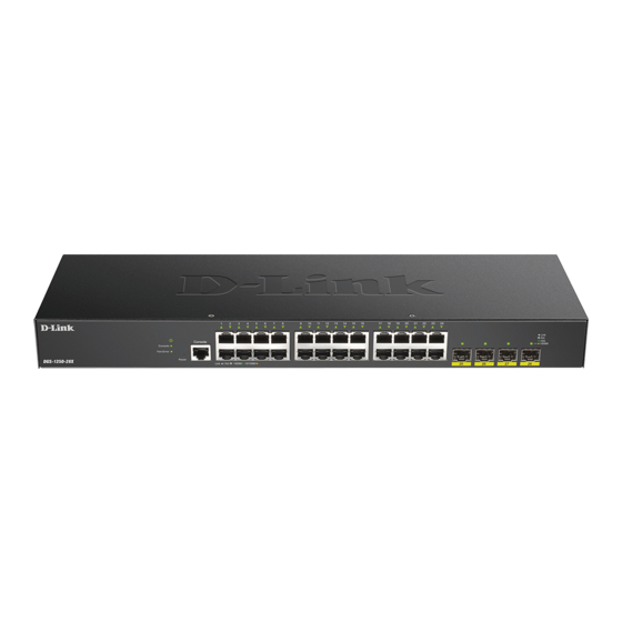
DGS-1250 Series Gigabit Ethernet Smart Managed Switch Hardware Installation Guide Figure 1-1 Front panel view of the DGS-1250-28X Figure 1-2 Front panel view of the DGS-1250-28XMP Figure 1-3 Front panel view of the DGS-1250-52X Figure 1-4 Front panel view of the DGS-1250-52XMP Ports Ports that can be found on the front panel of this switch are listed in the table below. -
Page 9: Reset Button
DGS-1250 Series Gigabit Ethernet Smart Managed Switch Hardware Installation Guide Reset Button On the front panel of the Switch is a Reset button. The Switch will reboot or reset to factory default settings depending on how long this button is pressed. -
Page 10: Rear Panel Components
DGS-1250 Series Gigabit Ethernet Smart Managed Switch Hardware Installation Guide Description Fan Error This LED will light solid red when the fan fails. This LED will be off when the fan is operating normally. PWR Max. This LED will light solid red when the power supplied to attached PDs exceeds the maximum PoE budget. -
Page 11: Side Panel Components
DGS-1250 Series Gigabit Ethernet Smart Managed Switch Hardware Installation Guide Figure 1-12 Rear panel view of the DGS-1250-52XMP Components that can be found on the rear panel of this switch are listed in the table below. Component Description Security Lock Provide a Kensington-compatible security lock to be able to connect to a secure immovable device. -
Page 12: Smart Fans
Figure 1-16 Side panels of the DGS-1250-52XMP Smart Fans The DGS-1250 Series Switches includes smart fans that will automatically change their speed depending on the internal temperature detected by the sensors built-in the Switch’s hardware. The following will explain at what temperature the speed of the fan(s) will change: •... -
Page 13: Installation
DGS-1250 Series Gigabit Ethernet Smart Managed Switch Hardware Installation Guide 2. Installation Installation Guidelines Installing the Switch without a Rack Installing the Switch in a Standard 19" Rack Installing Transceivers into the Transceiver Ports Power On (AC Power) Installation Guidelines This section will discuss the hardware installation guidelines that the user must follow in order to properly and safely install this switch into the appropriate environment. -
Page 14: Installing The Switch In A Standard 19" Rack
DGS-1250 Series Gigabit Ethernet Smart Managed Switch Hardware Installation Guide within 1.82 meters (6 feet) of the Switch. Make sure that there is proper heat dissipation from and adequate ventilation around the Switch. Leave at least 10 cm (4 inches) of space at the front, sides, and rear of the Switch for ventilation. -
Page 15: Installing Transceivers Into The Transceiver Ports
DGS-1250 Series Gigabit Ethernet Smart Managed Switch Hardware Installation Guide Installing Transceivers into the Transceiver Ports The Switch is equipped with Small Form-factor Pluggable (SFP) and Enhanced Small Form-factor Pluggable (SFP+) ports that can be used to connect various other networking devices to this switch that do not support the standard RJ45 wiring connection. -
Page 16: Power Failure (Ac Power)
DGS-1250 Series Gigabit Ethernet Smart Managed Switch Hardware Installation Guide Power Failure (AC Power) In the event of a power failure, just as a precaution, unplug the power cord from the Switch. Afterthe power returns, plug the power cord back into the power socket of the Switch. - Page 17 DGS-1250 Series Gigabit Ethernet Smart Managed Switch Hardware Installation Guide 3. Slide the retainer through the tie wrap until the end of the cord. Figure 2-7 Slide the Retainer through the Tie Wrap 4. Circle the tie of the retainer around the power cord and into the locker of the retainer.
- Page 18 DGS-1250 Series Gigabit Ethernet Smart Managed Switch Hardware Installation Guide 5. Fasten the tie of the retainer until the power cord is secured. Figure 2-9 Secure the power cord...
-
Page 19: Switch Connections
DGS-1250 Series Gigabit Ethernet Smart Managed Switch Hardware Installation Guide 3. Switch Connections Switch to an End Node Switch to Another Switch Switch to a Server Switch to an End Node An end node is a generic name for edge networking devices that will be connected to this switch. Typical examples of end nodes are Personal Computers (PCs), Notebooks, Access Points, Print Servers, VoIP Phones and more. -
Page 20: Switch To A Server
DGS-1250 Series Gigabit Ethernet Smart Managed Switch Hardware Installation Guide Switch to a Server The Switch is ideal for connecting to a network backbone, server, or server farm. The RJ45ports operate at a speed of 10/100/1000 Mbps. The SFP ports operate at a speed of 100/1000 Mbps. The SFP/SFP+ ports operate at a speed of 1/10 Gbps. -
Page 21: Switch Management
Switch. Most of the features available through the CLI can be accessed through the Web UI. Web browsers like Microsoft’s Internet Explorer, Mozilla Firefox, Google Chrome, or Safari can be used. For more detailed information about the Web UI, refer to the DGS-1250 Series Web UI Reference Guide. Connecting to the Console Port The front panel of the Switch provides an RJ45 console port to connect a remote system for monitoring and configuring the Switch. -
Page 22: Connecting To The Switch For The First Time
DGS-1250 Series Gigabit Ethernet Smart Managed Switch Hardware Installation Guide Figure 4-1 COM Port Configuration To be able to view the boot procedure, the Switch needs to be rebooted. The simplest way, at this stage, to reboot the Switch is to unplug and re-insert the power cable from and into the power receptacle on the back of the Switch. -
Page 23: Creating A User Account
DGS-1250 Series Gigabit Ethernet Smart Managed Switch Hardware Installation Guide DGS-1250-28XMP Gigabit Ethernet Smart Managed Switch Command Line Interface Firmware: Build 1.00.038 Copyright(C) 2019 D-Link Corporation. All rights reserved. User Access Verification Username:admin Password:***** NOTE: For security reasons, it is highly recommended to configure a personal username and password for this Switch. -
Page 24: Connecting Using Snmp
DGS-1250 Series Gigabit Ethernet Smart Managed Switch Hardware Installation Guide 1. We entered the Global Configuration Mode by entering the configure terminal command. 2. Then we entered the VLAN Configuration Mode of the default VLAN, which is VLAN 1, by entering the interface vlan 1 command. -
Page 25: Management Information Base (Mib)
DGS-1250 Series Gigabit Ethernet Smart Managed Switch Hardware Installation Guide Management Information Base (MIB) A Management Information Base (MIB) stores management and counter information. The Switch uses the standard MIB-II Management Information Base module. Consequently, values for MIB objects can be retrieved from any SNMP-based network management software. -
Page 26: Web-Based Switch Configuration
DGS-1250 Series Gigabit Ethernet Smart Managed Switch Hardware Installation Guide 5. Web-based Switch Configuration Introduction Logging into the Web UI Web User Interface (Web UI) Introduction Most software functions of the Switch can be managed, configured, and monitored via the embedded HTML Web UI. -
Page 27: Web User Interface (Web Ui)
DGS-1250 Series Gigabit Ethernet Smart Managed Switch Hardware Installation Guide Figure 5-2 Web UI Login Window Enter the User Name and Password in the corresponding fields and click Login. This will open the Web UI. Management features available in the Web UI of the Switch are explained below. -
Page 28: Areas Of The Web Ui
Switch. This area displays the Switch’s ports and expansion modules. It also shows port activity based on a specific mode. Some management functions, including port monitoring, are accessible from here. Click the D-Link logo to go to the D-Link website. - Page 29 DGS-1250 Series Gigabit Ethernet Smart Managed Switch Hardware Installation Guide Folder Name Description System Features regarding the Switch’s configuration can be viewed and configured in this folder. Management Features regarding the Switch’s management can be viewed and configured in this folder.
-
Page 30: Appendix A - Technical Specifications
DGS-1250 Series Gigabit Ethernet Smart Managed Switch Hardware Installation Guide Appendix A - Technical Specifications General Feature Description Data Transfer Rates Half-duplex Full-duplex Ethernet 10 Mbps 20 Mbps Fast Ethernet 100 Mbps 200 Mbps Gigabit Ethernet 2 Gbps 10 Gigabit Ethernet... -
Page 31: Performance
DGS-1250 Series Gigabit Ethernet Smart Managed Switch Hardware Installation Guide Feature Description Temperature Operating: -5 °C to 50 °C (23 °F to 122 °F) Storage: -20 °C to 70 °C (-4 °F to 158 °F) Humidity Operating: 0 % to 95 % RH (non-condensing) -
Page 32: Led Indicators
DGS-1250 Series Gigabit Ethernet Smart Managed Switch Hardware Installation Guide Feature Description MAC Address Table DGS-1250-28X: 16K DGS-1250-28XMP: 16K DGS-1250-52X: 32K DGS-1250-52XMP: 32K Supports 256 Static MAC addresses LED Indicators Location Color Status Description Per Device Power Green Light on (Solid) -
Page 33: Port Functions
DGS-1250 Series Gigabit Ethernet Smart Managed Switch Hardware Installation Guide Location Color Status Description (DGS-1250-28XMP Light blinking When there is reception or transmission and DGS-1250- of data occurring at 100Mbps 52XMP Only) Light off Link down or no link LED per... - Page 34 DGS-1250 Series Gigabit Ethernet Smart Managed Switch Hardware Installation Guide Feature Description • DEM-331R (1000BASE-BX-U, single-mode, 40 km, TX: 1310 nm / RX: 1550 nm) SFP+ Transceivers Supported: • DEM-431XT (10GBASE-SR,multi-mode, 80 km, without DDM) • DEM-432XT (10GBASE-LR, single-mode, 10 km, without DDM) •...
-
Page 35: Appendix B - Cables And Connectors
DGS-1250 Series Gigabit Ethernet Smart Managed Switch Hardware Installation Guide Appendix B - Cables and Connectors Ethernet Cable When connecting the Switch to another switch, a bridge or hub, a straight-through Cat5/5e/6a/7 cable is necessary. Please review these products for matching cable pin assignment. -
Page 36: Console Cable (Rj45 To Rs-232)
DGS-1250 Series Gigabit Ethernet Smart Managed Switch Hardware Installation Guide Console Cable (RJ45 to RS-232) A console cable is used to connect to the RJ45 console port of the Switch to access the command line interface. The following diagram and table show the standard RJ45 to RS-232cable and pin assignments. -
Page 37: Safety/Sécurité
DGS-1250 Series Gigabit Ethernet Smart Managed Switch Hardware Installation Guide Safety/Sécurité Safety Instructions Please pay careful attention to the following safety guidelines to ensure your own personal safety and to help protect your system from potential damage. Safety Cautions To greatly reduce the risk of physical injury, electrical shock, fire, and damage to equipment, observe the following precautions. -
Page 38: Consignes De Sécurité
DGS-1250 Series Gigabit Ethernet Smart Managed Switch Hardware Installation Guide When connecting or disconnecting power to and from hot-pluggable power supplies, observe the following guidelines: • Install the power supply before connecting the power cable to the power supply. •... -
Page 39: General Precautions For Rack-Mountable Products
DGS-1250 Series Gigabit Ethernet Smart Managed Switch Hardware Installation Guide • Assurez-vous que les caractéristiques nominales des appareils branchés correspondant à la tension du réseau électrique. • Utilisez uniquement des câbles d'alimentation homologués. Si un câble d'alimentation n'est pas fourni pour le système ou pour un composant/accessoire alimenté... -
Page 40: Protecting Against Electrostatic Discharge
DGS-1250 Series Gigabit Ethernet Smart Managed Switch Hardware Installation Guide • Before working on the rack, make sure that the stabilizers are secured to the rack, extended to the floor, and that the full weight of the rack rests on the floor. Install front and side stabilizers on a single rack or front stabilizers for joined multiple racks before working on the rack. -
Page 41: Warranty & Technical Support
The customer must submit with the product as part of the claim a written description of the Hardware defect or Software nonconformance in sufficient detail to allow D-Link to confirm the same, along with proof of purchase of the product (such as a copy of the dated purchase invoice for the product) if the product is not registered. - Page 42 D-Link Corporation/D-Link Systems, Inc., as stipulated by the United States Copyright Act of 1976 and any amendments thereto. Contents are subject to change without prior notice. Copyright 2004 by D-Link Corporation/D-Link Systems, Inc.
- Page 43 Product Registration Register your D-Link product online at http://support.dlink.com/register/ Product registration is entirely voluntary and failure to complete or return this form will not diminish your warranty rights.
- Page 44 This guide is only for initial configuration. Please refer to the user manual to learn more or visit http://www.mydlink.com for more information. Also feel free to contact us. U.S. and Canadian customers can contact D-Link Technical Support through our website. http://support.dlink.com Canada...
- Page 45 Europe customers TECHNICAL SUPPORT TECHNISCHE UNTERSTÜTZUNG ASSISTANCE TECHNIQUE ASISTENCIA TÉCNICA SUPPORTO TECNICO TECHNISCHE ONDERSTEUNING POMOC TECHNICZNA TECHNICKÁ PODPORA TECHNICKÁ PODPORA dlink.com/support TECHNIKAI TÁMOGATÁS TEKNISK SUPPORT TEKNISK SUPPORT TEKNISK STØTTE TEKNINEN TUKI ASSISTÊNCIA TÉCNICA ΤΕΧΝΙΚΉ ΥΠΟΣΤΉΡΙΞΗ TEHNIČKA PODRŠKA TEHNIČNA PODPORA SUPORT TEHNIC ТЕХНИЧЕСКА...
- Page 46 Indonesia - www.dlink.co.id Malaysia - www.dlink.com.my Philippines - www.dlink.com.ph Vietnam - www.dlink.com.vn Korea customers Tel : 1899-3540 Monday to Friday 9:30am to 6:30pm Web : http://d-link.co.kr E-mail : support@kr.dlink.com New Zealand customers Tel: 0800-900-900 24/7 Technical Support Web: http://www.dlink.co.nz E-mail: support@dlink.co.nz...
- Page 47 D-Link Middle East Dubai, U.A.E. Tel: +971-4-8809022 Fax: +971-4-8809066 / 8809069 Technical Support: +971-4-8809033 General Inquiries: info.me@me.dlink.com Tech Support: support.me@me.dlink.com Egypt Technical Support Call Center: +20 2258 66777 General Inquiries: info.eg@me.dlink.com Tech Support : support.eg@me.dlink.com Kingdom of Saudi Arabia: Technical Support: +966 1121 70009 General Inquiries: info.sa@me.dlink.com...
- Page 48 Обновления программного обеспечения и документация доступны на Интернет-сайте D-Link. D-Link предоставляет бесплатную поддержку для клиентов в течение гарантийного срока. Клиенты могут обратиться в группу технической поддержки D-Link по телефону или через Интернет. Техническая поддержка компании D-Link работает в круглосуточном режиме ежедневно, кроме официальных праздничных дней. Звонок...
- Page 49 Офисы Россия Հայաստան Москва, Графский переулок, 14 Երևան, Դավթաշեն 3-րդ Тел. : +7 (495) 744-00-99 թաղամաս, 23/5 E-mail: mail@dlink.ru Հեռ.՝ +374 (10) 39-86-67 Էլ. փոստ՝ info@dlink.am Україна Київ, вул. Межигірська, 87-А Latvija Тел.: +38 (044) 545-64-40 Rīga, Lielirbes iela 27 E-mail: ua@dlink.ua Tel.: +371 (6) 761-87-03 E-mail: info@dlink.lv...
- Page 50 Soporte Técnico Para Usuarios En Latino America Por favor revise el número telefónico del Call Center de su país en http://www.dlinkla.com/soporte/call-center Soporte Técnico de D-Link a través de Internet Horario de atención Soporte Técnico en www.dlinkla.com e-mail: soporte@dlinkla.com & consultas@dlinkla.com Clientes de Brasil Caso tenha dúvidas na instalação do produto, entre em contato com o...
- Page 51 台灣電子郵件: dssqa_service@dlink.com.tw 產品保固期限、台灣區技術諮詢時間、維修據點查詢,請參考 http://www.dlink.com.tw 網頁說明 香港、澳門 D-Link 技術諮詢專線 香港技術諮詢服務專線 (852) 8100 8892 香港服務時間: 週一至週五 10:00 ~ 13:00 及 14:00 ~ 18:00 週六 09:00 ~ 13:00 / 週日及公眾假期休息 http://www.dlink.com.hk 香港網站: 香港電子郵件: service@cn.synnex-grp.com 香港、澳門維修據點查詢請參考 http://www.dlink.com.hk/contact.html 網頁說明。 如果您是其他地區的用戶,請參考 D-Link 網站 www.dlink.com 查詢全球各地分公司的聯絡 資訊以取得相關支援服務。...
- Page 52 Pelanggan Indonesia Update perangkat lunak dan dokumentasi pengguna dapat diperoleh pada situs web D-Link. Dukungan Teknis untuk pelanggan: Tel: 0800-14014-97 (Layanan Bebas Pulsa) Dukungan Teknis D-Link melalui Internet: Pertanyaan Umum: sales@id.dlink.com Bantuan Teknis: support@id.dlink.com Website : http://www.dlink.co.id 日本のお客様 この度は弊社製品をお買い上げいただき、誠にありがとうございます。 製品に同梱されている保証書の購入元にお問い合わせください。...
- Page 53 8. What category best describes your company? Aerospace Engineering Education Finance Hospital Legal Insurance/Real Estate Manufacturing Retail/Chain store/Wholesale Government Transportation/Utilities/Communication System house/company Other________________________________ 9. Would you recommend your D-Link product to a friend? Don't know yet 10.Your comments on this product? __________________________________________________________________________________________ __________________________________________________________________________________________...