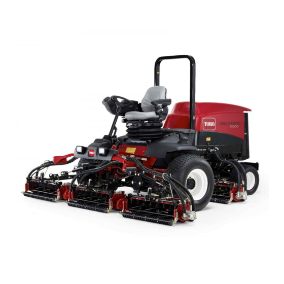
Toro Reelmaster 7000-D Operator's Manual
4-wheel drive traction unit
Hide thumbs
Also See for Reelmaster 7000-D:
- Service manual (468 pages) ,
- Operator's manual (144 pages) ,
- Installation instructions (2 pages)

Related Manuals for Toro Reelmaster 7000-D


Summary of Contents for Toro Reelmaster 7000-D
- Page 1 Form No. 3417-124 Rev A Reelmaster ® 7000-D 4-Wheel Drive Traction Unit Model No. 03780—Serial No. 400380001 and Up *3417-124* A Register at www.Toro.com. Original Instructions (EN)
- Page 2 Whenever you need service, genuine Toro parts, or Proposition 65 Warning additional information, contact an Authorized Service This product contains a chemical Dealer or Toro Customer Service and have the model or chemicals known to the State of and serial numbers of your product ready. Figure 1...
-
Page 3: Table Of Contents
Contents Engine Safety ........... 52 Servicing the Air Cleaner ........52 Servicing the Engine Oil........53 Safety ............... 4 Servicing the Diesel-Oxidation Catalyst General Safety ........... 4 (DOC) and the Soot Filter ......55 Engine-Emission Certification......4 Fuel System Maintenance ........56 Safety and Instructional Decals ...... -
Page 4: Safety
Safety • Keep children out of the operating area. Never allow children to operate the machine. • Stop the machine and shut off the engine before This machine has been designed in accordance with servicing, fueling, or unclogging the machine. EN ISO 5395:2013 (when appropriate decals are applied) and ANSI B71.4-2017. - Page 5 decal93-6688 93–6688 decal117-4765 1. Warning—read the 2. Cutting hazard of hand or 117-4765 Operator’s Manual before foot—shut off the engine performing maintenance. and wait for all moving 1. Read the Operator's Manual. parts to stop. 2. Do not use starting aids. decal110-9642 decal117-4766 110-9642...
- Page 6 decal106-6754 106-6754 decal121-3887 1. Warning—do not touch the hot surface. 121–3887 2. Cutting/dismemberment hazard, fan and entanglement 1. Read the Operator’s Manual. hazard, belt—stay away from moving parts. decal121-3884 121–3884 1. Engine—stop 3. Engine—start 2. Engine—preheat decal125-4605 125–4605 decal112-5019 112-5019 1.
- Page 7 decalbatterysymbols Battery Symbols Some or all of these symbols are on your battery. decal120-1670 120-1670 1. Explosion hazard 6. Keep bystanders a safe distance from the battery. 1. Traction unit speed 3. Fast 7. Wear eye protection; 2. No fire, open flame, or 2.
- Page 8 decal120-1683 120-1683 1. Warning—read the Operator's Manual; do not operate the 4. Warning—do not park the machine on slopes; engage the parking brake, lower the cutting units, shut off the engine, and machine unless you have received training. remove the ignition key before leaving the machine. 2.
- Page 9 decal120-1686 120-1686 (Affix over Part No. 120-1683 for CE) Note: This machine complies with the industry standard stability test in the static lateral and longitudinal tests with the maximum recommended slope indicated on the decal. It is important that each operator review the slope operations instructions in the operator manual and review the conditions in which the machine is being operated to determine if the machine may be operated in the conditions that day and on that site.
-
Page 10: Setup
Setup Loose Parts Use the chart below to verify that all parts have been shipped. Procedure Description Qty. – No parts required Adjust the support rollers. Warning decal Replace the decal for CE Compliance. Hood-lock bracket Rivet Install the hood lock for European CE Screw (1/4 x 2 inch) Compliance. -
Page 11: Adjusting The Support Rollers
Adjusting the Support Replacing the Warning Rollers Decal for CE Compliance No Parts Required Parts needed for this procedure: Warning decal Procedure Depending on what width cutting units are to be Procedure installed on the traction unit, adjust the support rollers as follows: On machines requiring CE Compliance, affix the CE warning decal (Part No. - Page 12 g012629 Figure 6 1. CE lock bracket 2. Bolt and nut assembly g200373 Figure 4 Align the washers with the holes on the inside of the hood. 1. Hood latch Rivet the brackets and the washers to the hood (Figure Remove the 2 rivets securing the hood-latch bracket to the hood (Figure...
-
Page 13: Installing The Cutting Units
g012631 Figure 8 1. Bolt 3. Arm of the hood-lock bracket 2. Nut Tighten the bolt securely but do not tighten the nut. g003320 Figure 9 1. Counter weight All of the cutting units are shipped with the turf compensation spring mounted to the right side Installing the Cutting Units of the cutting unit. - Page 14 g003967 Figure 11 2. Rod bracket 1. Opposite carrier frame tab Mount the rod bracket to the cutting unit tabs with the carriage bolts and nuts (Figure 11). On the cutting unit, mount the left hose guide to the front of the cutting unit tabs when reinstalling the rod bracket (Figure 13).
- Page 15 Note: When installing or removing the cutting units, make sure that the hairpin cotter is installed in the spring-rod hole next to the rod bracket. Otherwise, the hairpin cotter must be installed in the hole in the end of the rod. Increase the steering on the rear cutting units by removing the 2 pivot spacers, hex-socket screws, and flange locknuts...
- Page 16 g003948 Figure 19 1. Lift-arm chain 3. Snapper pin g015977 Figure 17 2. Chain bracket 1. Snapper pin Coat the spline shaft of the reel motor with clean grease. Note: Fixed steering is recommended when Oil the reel motor O-ring and install it onto the cutting on side hills.
-
Page 17: Adjusting The Turf-Compensation Spring
Adjusting the Using the Cutting-Unit Turf-Compensation Spring Kickstand No Parts Required Parts needed for this procedure: Cutting-unit kickstand Procedure The turf-compensation spring (Figure 21) transfers Procedure the weight from the front to the rear roller. This helps to reduce a wave pattern in the turf, also known as Whenever the cutting unit has to be tipped to expose marcelling or bobbing. -
Page 18: Greasing The Machine
Checking the Fluid Levels No Parts Required Procedure Check the level of the rear axle lubricant before the engine is first started, refer to (page Check the level of the hydraulic fluid before the engine is first started, refer to (page Check the level of the engine oil before and after the engine is first started, refer to... -
Page 19: Product Overview
Product Overview Controls Brake Pedals The 2 foot pedals (Figure 25) operate individual wheel brakes for turning assistance and to aid in obtaining better side hill traction. Pedal-Locking Latch The pedal-locking latch (Figure 25) connects the pedals together to engage the parking brake. g004552 Parking-Brake Pedal Figure 24... - Page 20 toward you to the most comfortable position and then diagnostics and other information about the machine release the pedal. (Figure 27). Mow-Speed Limiter PTO Switch When the mow-speed limiter (Figure 26) is flipped up The PTO switch (Figure 27) has 2 positions: S TART it will control the mow speed and allow the cutting and S...
- Page 21 Adjusting the Seat Fore and Aft Adjusting Lever Pull out on the lever to slide the seat fore or aft (Figure 30). Seat Armrest Adjusting Knob Rotate the knob to adjust the seat armrest angle (Figure 30). Seat Back Adjusting Lever Move the lever to adjust the seat back angle (Figure 30).
- Page 22 Using the InfoCenter LCD Display InfoCenter Icon Description SERVICE DUE Indicates when scheduled service The InfoCenter LCD display shows information about should be performed your machine such as the operating status, various diagnostics, and other information about the machine Hours remaining until service (Figure 31) There is a splash screen and main information screen of the InfoCenter.
- Page 23 Refer to the Service Output of TEC controller or control Manual or your Authorized wire in harness Toro Distributor for more information on the Faults High: over allowed range menu and the information contained there.
- Page 24 Controls the amount of time Auto Idle If you changed the PIN code and forgot the allowed before returning the code, contact your Authorized Toro Distributor for engine to low idle when the machine is stationary assistance. Controls the number of blades...
- Page 25 Note: Rotate the key switch to the O position and then to the O position locks the protected menu. You have the ability to view and change the settings in the Protected Menu. Once you access the Protected Menu, scroll down to Protect Settings option. Use the right button to change the setting.
-
Page 26: Specifications
Contact your Authorized Service Dealer or Distributor or go to www.Toro.com for a list of all approved attachments and accessories. To best protect your investment and maintain optimal performance of your Toro equipment, count on Toro genuine parts. -
Page 27: Operation
Filling the Fuel Tank Operation Note: Fuel Tank Capacity Determine the left and right sides of the machine from the normal operating position. 83 L (22 US gallons) Before Operation Safety Fuel Specification Important: Use only ultra-low sulphur diesel General Safety fuel. -
Page 28: Checking The Hydraulic System
• Fuel filter plugging may be expected for a time after converting to biodiesel blends. • Contact your Authorized Toro Distributor if you wish for more information on biodiesel. g200372 Figure 34 1. Fuel-tank cap Fill the tank until the level is to the bottom of the filler neck with fuel. -
Page 29: Checking The Engine-Oil Level
Checking the Engine-Oil If the coolant is low, add a 50/50 mixture of water and ethylene glycol antifreeze. Level Note: Do not use water only or alcohol/methanol-based coolants. Before you start the engine and use the machine, check the oil level in the engine crankcase; refer to Install the radiator cap and the expansion-tank Servicing the Engine Oil (page 53). -
Page 30: Checking The Tire Pressure
• Use accessories, attachments, and replacement • Never carry passengers on the machine and keep parts approved by The Toro® Company only. bystanders and pets away from the machine during operation. Rollover Protection System •... -
Page 31: Starting And Shutting Off The Engine
Starting and Shutting Off • Be aware that there is no rollover protection when a folded roll bar is in the down position. the Engine • Check the area that you will be mowing and never fold down a folding roll bar in areas where there are slopes, drop-offs, or water. -
Page 32: Engine Speed Switch
Diesel Particulate Filter Note: Lower the cutting units to the ground whenever you park the machine. This relieves the hydraulic load Regeneration from the system, prevents wear on system parts, and also prevents accidental lowering of the cutting units. The diesel particulate filter (DPF) is part of the exhaust Return the engine speed to low idle. - Page 33 DPF Soot Accumulation • DPF regeneration is a process that heats the DPF to convert the soot to ash. • Over time, the DPF accumulates soot in the soot • In addition to the warning messages, the computer filter. The computer for the engine monitors the reduces the power produced by the engine at soot level in the DPF.
- Page 34 DPF Ash Accumulation • When enough ash accumulates, the engine computer sends information to the InfoCenter in • The lighter ash is discharged through the exhaust the form of a system advisory or an engine fault to system; the heavier ash collects in the soot filter. indicate the accumulation of ash in the DPF.
- Page 35 Types of Diesel Particulate Filter Regeneration Types of diesel particulate filter regeneration that are performed while the machine is operating: Type of Regeneration Conditions for DPF regeneration DPF description of operation Passive Occurs during normal operation of the machine at The InfoCenter does not display an icon indicating high-engine speed or high-engine load passive regeneration.
- Page 36 DPF is already in need of a parked When the recovery-regeneration icon regeneration displayed in the InfoCenter, a recovery regeneration is requested. Contact your Authorized Toro Distributor to have a service technician perform the recovery regeneration. • A recovery regeneration requires up to 4 hours to complete.
- Page 37 Reset Regeneration Parked Regeneration g214713 g214711 Figure 44 Figure 43 Parked-regeneration request icon Assist/reset-regeneration icon • The parked-regeneration requested icon displays • The assist/reset-regeneration icon displays in the in the InfoCenter (Figure 44). InfoCenter (Figure 43). • If a parked regeneration is needed, the InfoCenter •...
- Page 38 Engage the parking brake. Set the throttle to the low I position. Performing a Parked Regeneration Note: For instructions on unlocking protected menus, refer to Accessing Protected Menus (page 24). Access the protected menu and unlock the protected settings submenu (Figure 46);...
- Page 39 g211986 g212405 Figure 50 Figure 52 Move the throttle control to and press LOW IDLE The “Waiting on ” message displays the center button (Figure 51). (Figure 53). g212372 g212406 Figure 51 Figure 53 The following messages display as the parked The computer determines whether the regeneration process begins: regeneration runs.
- Page 40 The engine is cold—wait. The engine is warm—wait. The engine hot—regeneration in progress (percent complete). The parked regeneration is complete when the “Regen Complete” message displays in the InfoCenter. Press the left button to exit to the home screen (Figure 56).
-
Page 41: Adjusting The Lift-Arm Counterbalance
A recovery regeneration requires up to 4 hours to complete. • You need a distributor technician to perform the recovery regeneration process; contact your Authorized Toro Distributor. Adjusting the Lift-Arm Counterbalance g015078 Figure 58 You can adjust the counterbalance on the rear 1. -
Page 42: Folding The Roll Bar
turnaround height or move the switch down to Insert the clevis pins in the lower holes and decrease the lift-arm turnaround height. secure them with the snap pins to support the upper frame in its lowered position. Tighten the mounting screws. To raise the frame, follow these instructions in reverse order. -
Page 43: After Operation Safety
4-wheel-drive manifold. interlock system that should be corrected before The following Toro parts are needed to bypass the beginning operation. check valve: •... - Page 44 g009703 Figure 63 1. Bypass valve g033131 Figure 61 When you are finished pushing or towing the 1. Rear traction manifold 2. Unmarked port (behind front left wheel) machine, remove the hydraulic hose that you installed. Connect a hydraulic hose between the Install the existing cap onto the reverse traction diagnostic fitting installed in the rear traction pressure test port.
-
Page 45: Hauling The Machine
Hauling the Machine To maintain enough power for the machine while operating, regulate the traction pedal to keep the • Use full-width ramps for loading the machine onto engine speed high and somewhat constant. A good a trailer or truck. rule to follow is to decrease the ground speed as the load on the cutting units increases, and increase the •... - Page 46 Understanding the Warning System If a warning light comes on during operation, stop the machine immediately and correct the problem before continuing operation. Serious damage could occur if you operate the machine with a malfunction. Mowing Grass Start the engine and move the engine speed switch to the F position.
-
Page 47: Maintenance
Maintenance Note: Determine the left and right sides of the machine from the normal operating position. Recommended Maintenance Schedule(s) Maintenance Service Maintenance Procedure Interval • Torque the wheel nuts. After the first 8 hours • Change the front planetary-gear oil. •... -
Page 48: Daily Maintenance Checklist
Daily Maintenance Checklist Duplicate this page for routine use. Maintenance For the week of: Check Item Mon. Tues. Wed. Thurs. Fri. Sat. Sun. Check the safety interlock operation. Check the brake operation. Check the levels of the engine oil and fuel. Check the cooling-system fluid level. -
Page 49: Service Interval Chart
Item Date Information Important: Refer to your engine operator's manual and cutting unit Operator's Manual for additional maintenance procedures. Note: To obtain an electrical schematic or a hydraulic schematic for your machine, visit www.Toro.com. Service Interval Chart decal130-1651 Figure 65... -
Page 50: Pre-Maintenance Procedures
CAUTION If you leave the key in the ignition switch, someone could accidently start the engine and seriously injure you or other bystanders. Remove the key from the ignition before you do any maintenance. Pre-Maintenance Procedures Pre-Maintenance Safety • Before adjusting, cleaning, repairing, or leaving the machine, do the following: –... -
Page 51: Lubrication
Lubrication • Steering cylinder ball joints (2) (Figure Greasing the Bearings and Bushings Service Interval: Every 50 hours The machine has grease fittings that must be lubricated regularly with No. 2 lithium grease. If the machine is operated under normal conditions, lubricate all bearings and bushings after every 50 hours of operation or immediately after every washing. -
Page 52: Engine Maintenance
Engine Maintenance • Cutting unit carrier frame (2 per cutting unit) (Figure • Cutting unit lift arm pivot (1 per cutting unit) (Figure Engine Safety • Shut off the engine before checking the oil or adding oil to the crankcase. •... -
Page 53: Servicing The Engine Oil
Preferred oil: SAE 15W-40 (above 0°F) • Alternate oil: SAE 10W-30 or 5W-30 (all temperatures) Toro Premium Engine Oil is available from your Authorized Toro Distributor in either 15W-40 or g011504 Figure 74 10W-30 viscosity grades. See the parts catalog for part numbers. - Page 54 Checking the Engine-Oil Level Install the oil-fill cap and dipstick. Close the hood and secure it with the latches. Service Interval: Before each use or daily The engine is shipped with oil in the crankcase; Crankcase Oil Capacity however, the oil level must be checked before and after the engine is first started.
-
Page 55: Servicing The Diesel-Oxidation Catalyst (Doc) And The Soot Filter
Apply a light coat of clean oil to the new filter assembling the diesel-oxidation catalyst and seal before installing it. the soot filter of the DPF. Refer to your Authorized Toro Distributor for Note: Do not overtighten the filter. diesel-oxidation catalyst and the soot filter Add oil to the crankcase;... -
Page 56: Fuel System Maintenance
Servicing the Water Fuel System Separator Maintenance Service Interval: Before each use or daily—Drain DANGER water or other contaminants from the water separator. Under certain conditions, fuel and fuel vapors Every 400 hours—Replace the fuel filter are highly flammable and explosive. A fire or canister. -
Page 57: Cleaning The Fuel-Intake Screen
Electrical System Maintenance Electrical System Safety • Disconnect the battery before repairing the machine. Disconnect the negative terminal first and the positive last. Connect the positive terminal first and the negative last. • Charge the battery in an open, well-ventilated area, away from sparks and flames. - Page 58 Battery electrolyte contains sulfuric acid, which is fatal if consumed and causes Coat both battery connections with Grafo 112X severe burns. (skin-over) grease, Toro Part No. 505-47, petroleum jelly, or light grease to prevent • Do not drink electrolyte and avoid corrosion.
-
Page 59: Servicing The Battery
Rinse the case with clean water. Coat the battery posts and cable connectors with Grafo 112X (skin-over) grease (Toro Part No. 505-47) or petroleum jelly to prevent corrosion. Checking the Fuses The fuses are located under the operator’s control panel. -
Page 60: Drive System Maintenance
Drive System Maintenance g225611 Figure 88 g016642 Figure 87 1. Fuses Checking the Torque of the Wheel Nuts Service Interval: After the first 8 hours Every 200 hours Park the machine on a level surface, lower the cutting units, engage the parking brake, shut off the engine, and remove the key. -
Page 61: Checking The Planetary Gear-Drive Lubricant
Figure 89 1. Front drive wheels Repeat step for the other drive wheel. If either wheel moves, contact your authorized Toro distributor to have the planetary drive g225606 rebuilt. Figure 91 1. Check-plug hole 2. Check plug Checking the Planetary... -
Page 62: Changing The Planetary-Gear-Drive Oil
Changing the Planetary-Gear-Drive Oil Service Interval: After the first 200 hours Every 800 hours or yearly, whichever comes first. Lubricant specification: high quality SAE 85W-140 gear lubricant Planetary and brake housing lubrication capacity: 0.65 L (22 fl oz) g225608 Figure 93 Draining the Planetary-Gear-Drive 1. -
Page 63: Checking The Oil Level Of The Rear Axle
Changing the Oil in the Rear Axle Service Interval: After the first 200 hours Every 800 hours Park the machine on a level surface, lower the cutting units, engage the parking brake, shut off the engine, and remove the key. Clean the area around the 3 drain plugs, 1 on each end and 1 in the center (Figure... -
Page 64: Adjusting The Traction Drive For Neutral
level is low, add enough lubricant to bring the level up to the bottom of the hole. g009987 Figure 99 1. Pump-rod jam nuts 2. Pump control tube After the wheel rotation ceases, tighten the jam nuts to secure the adjustment. Shut off the engine and release the right brake. -
Page 65: Cooling System Maintenance
Cooling System Maintenance Cooling System Safety • Swallowing engine coolant can cause injury or death; keep out of reach from children and pets. • g009718 Discharge of hot, pressurized coolant or touching Figure 101 a hot radiator and surrounding parts can cause severe burns. -
Page 66: Brake Maintenance
Brake Maintenance Clean both sides of the oil cooler/radiator area (Figure 103) thoroughly with compressed air. Start from the front and blow the debris out toward the back. Then clean from the back Adjusting the Service side and blow toward the front. Repeat the Brakes procedure several times until all chaff and debris is removed. -
Page 67: Belt Maintenance
Toro distributor for part numbers). 1. Alternator 2. Mounting bolt Alternative fluids: If the Toro fluid is not available, other conventional, petroleum-based fluids may be used, provided that they meet all of the following Increase or decrease the tension of the material properties and industry specifications. -
Page 68: Changing The Hydraulic Fluid
Mobil EAL EnviroSyn 46H is the only synthetic biodegradable fluid approved by Toro. This fluid is compatible with the elastomers used in Toro hydraulic systems and is suitable for a g200375 Figure 106 wide range of temperature conditions. This fluid is compatible with conventional fluids, but for 1. -
Page 69: Replacing The Hydraulic Filters
Change the 2 hydraulic filters initially after the first 200 operating hours. Thereafter, change the filters after every 800 operating hours, in normal conditions. Use Toro replacement filters Part No. 94-2621 for the rear (cutting unit) of the machine and 75-1310 for the front (charge) of the machine. -
Page 70: Checking The Hydraulic Lines And Hoses
Checking the Hydraulic Cutting Unit Maintenance Lines and Hoses Cutting Unit Safety Service Interval: Before each use or daily A worn or damaged cutting unit can break, and a Park the machine on a level surface, lower the cutting piece of a reel or bedknife could be thrown at you units, engage the parking brake, shut off the engine, or bystanders, resulting in serious personal injury or and remove the key. - Page 71 Be certain that you are clear of the Note: Additional instructions and procedures on backlapping are available in the Toro Sharpening cutting units before proceeding. Reel and Rotary Mowers Manual, Form No. 80-300SL. With the mow-speed limiter in the M...
-
Page 72: Storage
Clean the battery, terminals, and posts with a wire brush and baking-soda solution. Coat the cable terminals and battery posts with Grafo 112X skin-over grease (Toro Part No. 505-47) or petroleum jelly to prevent corrosion. Slowly charge the battery every 60 days for 24 hours to prevent lead sulfation of the battery. - Page 73 Notes:...
- Page 74 Notes:...
- Page 75 The Way Toro Uses Information Toro may use your personal information to process warranty claims, to contact you in the event of a product recall and for any other purpose which we tell you about. Toro may share your information with Toro's affiliates, dealers or other business partners in connection with any of these activities. We will not sell your personal information to any other company.
- Page 76 Countries Other than the United States or Canada Customers who have purchased Toro products exported from the United States or Canada should contact their Toro Distributor (Dealer) to obtain guarantee policies for your country, province, or state. If for any reason you are dissatisfied with your Distributor's service or have difficulty obtaining guarantee information, contact the Toro importer.