Huawei FusionServer Pro CH121 V5 V100R005 Maintenance And Service Manual
Compute node
Hide thumbs
Also See for FusionServer Pro CH121 V5 V100R005:
- Maintenance and service manual (162 pages)

Related Manuals for Huawei FusionServer Pro CH121 V5 V100R005


Summary of Contents for Huawei FusionServer Pro CH121 V5 V100R005
- Page 1 FusionServer Pro CH121 V5 Compute Node V100R005 Maintenance and Service Guide Issue Date 2019-08-10 HUAWEI TECHNOLOGIES CO., LTD.
- Page 2 Notice The purchased products, services and features are stipulated by the contract made between Huawei and the customer. All or part of the products, services and features described in this document may not be within the purchase scope or the usage scope. Unless otherwise specified in the contract, all statements, information, and recommendations in this document are provided "AS IS"...
-
Page 3: About This Document
NOTICE is used to address practices not related to personal injury. Calls attention to important information, best practices, and tips. NOTE is used to address information not related to personal injury, equipment damage, and environment deterioration. Issue 06 (2019-08-10) Copyright © Huawei Technologies Co., Ltd. - Page 4 Added information about the Avago SAS3408 and Avago SAS3004 iMR RAID controller cards. 2017-12-28 l Updated the memory module installation guidelines. 2017-10-12 l This issue is the first official release. Issue 06 (2019-08-10) Copyright © Huawei Technologies Co., Ltd.
-
Page 5: Table Of Contents
4.3 Field Replaceable Units..............................54 4.3.1 Removing an M.2 FRU............................. 54 4.3.2 Installing an M.2 FRU............................... 55 4.3.3 Removing the Screw-in RAID Controller Card......................56 4.3.4 Installing the Screw-in RAID Controller Card......................58 Issue 06 (2019-08-10) Copyright © Huawei Technologies Co., Ltd. - Page 6 8.1 Safety Instructions..............................114 8.2 Maintenance and Warranty............................117 9 ESD............................... 118 9.1 Preventing Electrostatic Discharge ..........................118 9.2 Grounding Methods to Prevent Electrostatic Discharge.....................118 10 Hardware Description......................120 10.1 Front Panel................................120 Issue 06 (2019-08-10) Copyright © Huawei Technologies Co., Ltd.
- Page 7 12.6.4 Logging In to a Compute Node or a Switch Module over SOL................160 12.7 Logging In to the Desktop of a Server........................162 12.7.1 Using the Remote Virtual Console........................162 12.7.1.1 iBMC.................................. 162 Issue 06 (2019-08-10) Copyright © Huawei Technologies Co., Ltd.
- Page 8 12.10 Clearing Data from a Storage Device........................175 A More Information........................178 A.1 Technical Support..............................178 A.2 Product Information..............................179 A.3 Product Configuration Resources..........................179 A.4 Maintenance Tools..............................180 B Appendix............................ 181 B.1 Product SN................................. 181 B.2 RAS Features................................182 Issue 06 (2019-08-10) Copyright © Huawei Technologies Co., Ltd.
-
Page 9: Overview
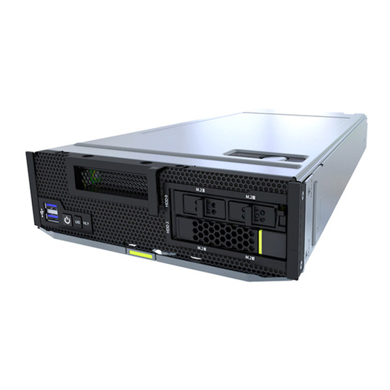
The CH121 V5 compute nodes are installed in an E9000 chassis and are centrally managed by the management module. Issue 06 (2019-08-10) Copyright © Huawei Technologies Co., Ltd. - Page 10 FusionServer Pro CH121 V5 Compute Node Maintenance and Service Guide 1 Overview Figure 1-1 CH121 V5 Issue 06 (2019-08-10) Copyright © Huawei Technologies Co., Ltd.
-
Page 11: Physical Structure
(Optional) USB flash drive (Optional) TPM Screw-in RAID controller card (Optional) Supercapacitor Heat sinks Mainboard (Optional) M.2 FRUs Drives (Optional) M.2 adapter Drive cage Processors Mezzanine card BIOS battery Memory modules Issue 06 (2019-08-10) Copyright © Huawei Technologies Co., Ltd. -
Page 12: Logical Structure
The storage module, consisting of a RAID controller card and a drive backplane, connects to the CPUs through PCIe buses. The BMC provides device management functions, such as compute node power control, slot number acquisition, PSU detection, and KVM over IP. Issue 06 (2019-08-10) Copyright © Huawei Technologies Co., Ltd. -
Page 13: Spare Parts Description
RSP and has warehouses near RSPs or NRSPs at sites based on the lower levels. contract service type, SLA, and service sites. Lower- level parts vary with actual demands. Issue 06 (2019-08-10) Copyright © Huawei Technologies Co., Ltd. - Page 14 NSP&SUB It is not a spare part, This part is not but has RSPs or stored. Lower-level NRSPs at lower parts vary with levels. actual demands. Issue 06 (2019-08-10) Copyright © Huawei Technologies Co., Ltd.
-
Page 15: Basic Operations
3.10 Installing the PCIe Card Panel 3.11 Removing a PCIe Card 3.12 Installing a PCIe Card 3.13 Removing a SAS/SATA Drive 3.14 Installing a SAS/SATA Drive 3.15 Removing an NVMe Drive 3.16 Installing an NVMe Drive Issue 06 (2019-08-10) Copyright © Huawei Technologies Co., Ltd. -
Page 16: Power-Off Procedure
12.3 Logging In to the MM910 WebUI. Step 3 On the HMM WebUI, choose PSUs&FANs. The PSUs&Fans page is displayed. Step 4 Choose PSU Management > Power Control from the navigation tree. Issue 06 (2019-08-10) Copyright © Huawei Technologies Co., Ltd. -
Page 17: Power-On Procedure
If the chassis is powered on and the compute node is in standby state (the power indicator is steady yellow), you can use any of the following methods to power on the compute node: – Use the MM910 WebUI. Issue 06 (2019-08-10) Copyright © Huawei Technologies Co., Ltd. -
Page 18: Removing A Ch121 V5
To power on all compute nodes at a time, select the check box in the header row and click Power On. ----End 3.3 Removing a CH121 V5 Procedure Step 1 Determine the position of the compute node in the chassis. Issue 06 (2019-08-10) Copyright © Huawei Technologies Co., Ltd. - Page 19 Fully open the ejector lever. See (2) in Figure 3-4. Holding the ejector lever, pull the compute node out of the chassis horizontally. See (3) Figure 3-4. Close the ejector lever. See (4) in Figure 3-4. Issue 06 (2019-08-10) Copyright © Huawei Technologies Co., Ltd.
- Page 20 Install filler panels in vacant slots. Otherwise, the ventilation, heat dissipation, electromagnetic shielding, and dustproof effects of the chassis will be affected. Insert the filler panel into the chassis horizontally until it clicks into place. Issue 06 (2019-08-10) Copyright © Huawei Technologies Co., Ltd.
-
Page 21: Installing A Ch121 V5
Maintenance and Service Guide 3 Basic Operations Figure 3-5 Installing a filler panel ----End 3.4 Installing a CH121 V5 Procedure Step 1 Determine the position of the compute node in the chassis. Issue 06 (2019-08-10) Copyright © Huawei Technologies Co., Ltd. - Page 22 Press and hold the groove inward on the filler panel to release the filler panel. See (1) in Figure 3-7. Remove the filler panel from the chassis. See (1) in Figure 3-7. Issue 06 (2019-08-10) Copyright © Huawei Technologies Co., Ltd.
- Page 23 See (1) and (2) in Figure 3-8. Pull the partition board outwards. See (3) and (4) in Figure 3-8. The partition board is properly installed when you hear a click. Issue 06 (2019-08-10) Copyright © Huawei Technologies Co., Ltd.
- Page 24 Figure 3-9 Installing a compute node Step 4 Power on the compute node. For details, see 3.2 Power-On Procedure. Step 5 Check indicator status. For details, see 10.1.2 Indicators and Buttons. ----End Issue 06 (2019-08-10) Copyright © Huawei Technologies Co., Ltd.
-
Page 25: Removing The Cover
3.6 Installing the Cover Procedure Step 1 Place the compute node on the ESD workstation. Step 2 Take the spare part out of its ESD bag. Step 3 Install the cover. Issue 06 (2019-08-10) Copyright © Huawei Technologies Co., Ltd. -
Page 26: Removing The Air Ducts
Step 3 Place the compute node on the ESD workstation. Step 4 Remove the cover. For details, see 3.5 Removing the Cover. Step 5 Determine the position of the air duct. Issue 06 (2019-08-10) Copyright © Huawei Technologies Co., Ltd. -
Page 27: Installing The Air Duct
Step 6 Determine the position of the air duct. Step 7 Check whether a PCIe card is installed. If yes, go to Step If no, go to Step Step 8 Transform the air duct. Issue 06 (2019-08-10) Copyright © Huawei Technologies Co., Ltd. - Page 28 Step 9 Align the right air duct with the right DIMMs, align the left air duct with the left DIMMs and heat sinks, and vertically place the air ducts downwards. Figure 3-14 Installing the air duct Issue 06 (2019-08-10) Copyright © Huawei Technologies Co., Ltd.
-
Page 29: Removing The Pcie Card Panel
Step 6 Loosen the two screws that secure the PCIe card panel and lift the PCIe card panel vertically. See (1) and (2) in Figure 3-15. Figure 3-15 Removing a PCIe card panel Issue 06 (2019-08-10) Copyright © Huawei Technologies Co., Ltd. -
Page 30: Installing The Pcie Card Panel
Vertically slide the PCIe card panel into the slot, and align the screw holes on the PCIe card panel with those on the pane. See (1) in Figure 3-16. Tighten the two screws to secure the PCIe card panel. See (2) in Figure 3-16. Issue 06 (2019-08-10) Copyright © Huawei Technologies Co., Ltd. -
Page 31: Removing A Pcie Card
Step 3 Place the compute node on the ESD workstation. Step 4 Remove the cover. For details, see 3.5 Removing the Cover. Step 5 Remove the air duct. For details, see 3.7 Removing the Air Ducts. Issue 06 (2019-08-10) Copyright © Huawei Technologies Co., Ltd. - Page 32 Loosen the three screws that secure the PCIe card bracket, and vertically lift the PCIe card bracket. See (1) and (2) in Figure 3-18. Remove the PCIe card from the PCIe card bracket in the arrow direction. See (3) in Figure 3-18. Issue 06 (2019-08-10) Copyright © Huawei Technologies Co., Ltd.
-
Page 33: Installing A Pcie Card
Step 2 Remove the compute node. For details, see 3.3 Removing a CH121 Step 3 Place the compute node on the ESD workstation. Step 4 Remove the cover. For details, see 3.5 Removing the Cover. Issue 06 (2019-08-10) Copyright © Huawei Technologies Co., Ltd. - Page 34 PCIe card filler panel align with the screw holes on the front panel. See (2) in Figure 3-20. Tighten the three screws to secure the PCIe card bracket. See (3) in Figure 3-20. Issue 06 (2019-08-10) Copyright © Huawei Technologies Co., Ltd.
- Page 35 3.6 Installing the Cover. Step 12 Install the compute node. For details, see 3.4 Installing a CH121 Step 13 Power on the compute node. For details, see 3.2 Power-On Procedure. ----End Issue 06 (2019-08-10) Copyright © Huawei Technologies Co., Ltd.
-
Page 36: Removing A Sas/Sata Drive
Step 2 Check the running status of the drive by observing its indicators. For details, see SAS/SATA Drive Indicators. Step 3 Determine whether the drive needs to be removed. If yes, go to Step If no, rectify the drive fault. Issue 06 (2019-08-10) Copyright © Huawei Technologies Co., Ltd. -
Page 37: Installing A Sas/Sata Drive
It will be cleared after the RAID array rebuild is complete. Do not frequently hot-swap a drive to prevent new alarms. l To prevent damage caused by insufficient heat dissipation and high temperature, install components or filler panels. Issue 06 (2019-08-10) Copyright © Huawei Technologies Co., Ltd. - Page 38 Fully open the ejector lever and push the drive into the slot as far as it will go. See (1) in Figure 3-24. Ensure that the ejector lever is fastened to the chassis beam, and then close it to completely insert the drive into the slot. See (2) in Figure 3-24. Issue 06 (2019-08-10) Copyright © Huawei Technologies Co., Ltd.
-
Page 39: Removing An Nvme Drive
If the OS is RHEL 7.3 and the VMD function is enabled, the OS kernel 3.10.0-514.el7.x86_64 must be used for surprise hot swap of NVMe drives. Otherwise, the operating system may restart. Issue 06 (2019-08-10) Copyright © Huawei Technologies Co., Ltd. - Page 40 Do not insert or remove drives frequently. If a drive is frequently removed and installed in an interval shorter than 30 seconds, there are risks that the drive cannot be identified. Issue 06 (2019-08-10) Copyright © Huawei Technologies Co., Ltd.
- Page 41 Intelligent Computing Compatibility Checker to obtain information about the Windows operating systems supported. l The following uses Windows Server 2012 R2 as an example. Step 1 Determine the slot and position of the drive. Issue 06 (2019-08-10) Copyright © Huawei Technologies Co., Ltd.
- Page 42 Figure 3-28. Determine the physical slot of the drive based on the slot ID. Table 3-1 lists the mapping between the slot IDs and physical slot numbers. Issue 06 (2019-08-10) Copyright © Huawei Technologies Co., Ltd.
- Page 43 VMD function is disabled. The following uses Huawei NVMe drive as an example to describe how to install the NVMe driver hiodriver and NVMe tool NVMe Toolbox. The NVMe Toolbox can be used to query NVMe drive information, upgrade the firmware, and perform hot swap.
- Page 44 After the drive is removed, "Eject Succeed" will be displayed. Figure 3-30 Success message NOTE If a failure message is displayed indicating that the NVMe drive is being accessed, stop the related services and click eject again. Issue 06 (2019-08-10) Copyright © Huawei Technologies Co., Ltd.
- Page 45 Step 2 Check the running status of the drive by observing its indicators. For details, see NVMe SSD Indicators. Step 3 Determine whether the drive needs to be removed. If yes, go to Step Issue 06 (2019-08-10) Copyright © Huawei Technologies Co., Ltd.
- Page 46 Figure 3-34 Configuring kernel parameters (2) Save the file and restart the compute node. Run the cat /proc/cmdline command. If the command output contains "pciehp.pciehp_force=1 pci=pcie_bus_perf", the kernel is configured successfully. Issue 06 (2019-08-10) Copyright © Huawei Technologies Co., Ltd.
- Page 47 Do not add the content in a new line. Figure 3-37 Configuring kernel parameters (1) Figure 3-38 Configuring kernel parameters (2) Save the file and restart the compute node. Issue 06 (2019-08-10) Copyright © Huawei Technologies Co., Ltd.
- Page 48 Run the uname -r command to check the current kernel version. Figure 3-42 Kernel version Log in to the official SUSE website to download the kernel upgrade package (kernel-3.10.0-514.26.2.e17.x86_64 for example). Issue 06 (2019-08-10) Copyright © Huawei Technologies Co., Ltd.
- Page 49 VMD function is disabled. Change the value of the a8 register. Otherwise, NVMe drives do not support orderly hot swap. Issue 06 (2019-08-10) Copyright © Huawei Technologies Co., Ltd.
- Page 50 -xxx -s 85:03.0 Figure 3-45 Querying the original register value NOTE If the default a8 register value is not f1, contact Huawei technical support. Change the value of the a8 register to e1. setpci -s <B/D/F> a8.B=e1 <B/D/F>: indicates the root port (B/D/F) of the NVMe drive. For details about the...
- Page 51 <B/D/F>: indicates the root port (B/D/F) of the NVMe drive. For details about the B/D/F information, see Table 3-2. Figure 3-47 Resetting the value of the a8 register of drive 2 (example) Issue 06 (2019-08-10) Copyright © Huawei Technologies Co., Ltd.
-
Page 52: Installing An Nvme Drive
You can use a USB flash drive to access the RHEL 7.3 graphical installation interface. For details, Installing RHEL 7.3 on an NVMe SSD. Step 1 Take the spare part out of its ESD bag. Step 2 Determine the slot and position of the drive. Issue 06 (2019-08-10) Copyright © Huawei Technologies Co., Ltd. - Page 53 – Download the NVMe driver of the latest version. – If no such driver is available, use the latest drive driver provided by the OS. Install drivers for Huawei series NVMe drives. To ensure the stable running of NVMe drives, the following OSs are supported: –...
- Page 54 NOTE – It is recommended that you install the latest driver. – If Huawei NVMe driver is installed on a server using both Intel NVMe drives and Huawei NVMe drives, the server cannot identify the Intel NVMe drives. Step 5 Install NVMe drives.
- Page 55 – Download the NVMe driver of the latest version. – If no such driver is available, use the latest drive driver provided by the OS. Install drivers for Huawei series NVMe drives. To ensure the stable running of NVMe drives, the following OSs are supported: –...
- Page 56 NOTE – It is recommended that you install the latest driver. – If Huawei NVMe driver is installed on a server using both Intel NVMe drives and Huawei NVMe drives, the server cannot identify the Intel NVMe drives. Step 5 Install NVMe drives.
- Page 57 If SUSE 12.2 is installed in UEFI: Run the cat /proc/cmdline command. If the command output does not contain "pciehp.pciehp_force=1 pci=pcie_bus_perf", you need to configure kernel parameters. Figure 3-54 Opening the configuration file Issue 06 (2019-08-10) Copyright © Huawei Technologies Co., Ltd.
- Page 58 Example 1: RHEL 7.3 Upgrade the kernel of RHEL 7.3 to kernel-3.10.0-514.26.2.e17.x86_64 or later to support orderly hot swap of NVMe drives. Run the uname -r command to check the current kernel version. Issue 06 (2019-08-10) Copyright © Huawei Technologies Co., Ltd.
- Page 59 (kernel-3.10.0-514.26.2.e17.x86_64 for example). Run the rpm -ivh kernel-default-4.4.74-92.32.1.x86_64.rpm command to upload the upgrade package to the OS for installation. Figure 3-61 Installing the upgrade package Issue 06 (2019-08-10) Copyright © Huawei Technologies Co., Ltd.
- Page 60 Download the NVMe driver for Windows Server 2012, and create an ISO or IMG file. Load the NVMe driver on the installation UI. After the NVMe drive is detected, proceed with the OS installation. ----End Issue 06 (2019-08-10) Copyright © Huawei Technologies Co., Ltd.
-
Page 61: Parts Replacement
CPU 1 and memory modules must be configured for CPU 1. Install air ducts above memory slots. The CMOS battery has sufficient power. Processors 1 and 2 use different heat sinks. The following heat sink configurations are available: Issue 06 (2019-08-10) Copyright © Huawei Technologies Co., Ltd. -
Page 62: Field Replaceable Units
Figure 4-1 Positions of the M.2 FRUs Step 2 Release the handle of the M.2 FRU, and pull out the M.2 FRU by holding its handle. See (1) and (2) in Figure 4-2. Issue 06 (2019-08-10) Copyright © Huawei Technologies Co., Ltd. -
Page 63: Installing An M.2 Fru
Perform this operation only when a M.2 FRU is not installed immediately. ----End 4.3.2 Installing an M.2 FRU Procedure Step 1 Determine the position of the M.2 FRU. Figure 4-3 Positions of the M.2 FRUs Step 2 Remove the filler panel. Issue 06 (2019-08-10) Copyright © Huawei Technologies Co., Ltd. -
Page 64: Removing The Screw-In Raid Controller Card
Step 2 Remove the compute node. For details, see 3.3 Removing a CH121 Step 3 Place the compute node on the ESD workstation. Step 4 Remove the cover. For details, see 3.5 Removing the Cover. Issue 06 (2019-08-10) Copyright © Huawei Technologies Co., Ltd. - Page 65 Step 10 Remove the RAID controller card. Loosen the screws that secure the RAID controller card. See (1) in Figure 4-6. Remove the RAID controller card from the connector on the mainboard. See (2) in Figure 4-6. Issue 06 (2019-08-10) Copyright © Huawei Technologies Co., Ltd.
-
Page 66: Installing The Screw-In Raid Controller Card
Step 6 Remove the PCIe card. For details, see 3.11 Removing a PCIe Card. Step 7 Take the spare part out of its ESD bag. Step 8 Determine the position of the screw-in RAID controller card. Issue 06 (2019-08-10) Copyright © Huawei Technologies Co., Ltd. - Page 67 If yes, go to Step If no, go to Step Step 11 Install the supercapacitor. For details, see 4.3.10 Installing the Supercapacitor. Step 12 Check whether a PCIe card is installed. Issue 06 (2019-08-10) Copyright © Huawei Technologies Co., Ltd.
-
Page 68: Removing The Avago Sas3004Imr Pcie Raid Control Card
Log in to the Configuration Utility. For details, see LSI SAS3008IR> Initial Configuration (Legacy/Dual Mode) or Initial Configuration (EFI/UEFI Mode) > Logging In to the Configuration Utility in Huawei V5 Server RAID Controller Card User Guide. Activate RAID. For details, see LSI SAS3008IR> Common Tasks (Legacy/Dual Mode) > Activating a... -
Page 69: Installing The Avago Sas3004Imr Pcie Raid Control Card
3.6 Installing the Cover. Step 12 Install the compute node. For details, see 3.4 Installing a CH121 Step 13 Power on the compute node. For details, see 3.2 Power-On Procedure. ----End Issue 06 (2019-08-10) Copyright © Huawei Technologies Co., Ltd. -
Page 70: Removing The M.2 Fru From The Avago Sas3004Imr Raid Controller Card
Procedure Step 1 Determine the position of the M.2 FRU on the Avago SAS3004iMR RAID controller card. Step 2 Install an M.2 FRU on the Avago SAS3004iMR PCIe RAID controller card. Issue 06 (2019-08-10) Copyright © Huawei Technologies Co., Ltd. -
Page 71: Removing The Supercapacitor
3.3 Removing a CH121 Step 3 Place the compute node on the ESD workstation. Step 4 Remove the cover. For details, see 3.5 Removing the Cover. Step 5 Determine the position of the supercapacitor. Issue 06 (2019-08-10) Copyright © Huawei Technologies Co., Ltd. - Page 72 Step 7 Place the removed component in an ESD bag. Step 8 Remove the supercapacitor holder. Loosen the screws that secure the supercapacitor holder. See (1) in Figure 4-13. Lift the supercapacitor holder. See (2) in Figure 4-13. Issue 06 (2019-08-10) Copyright © Huawei Technologies Co., Ltd.
-
Page 73: Installing The Supercapacitor
Step 4 Remove the cover. For details, see 3.5 Removing the Cover. Step 5 Take the spare part out of its ESD bag. Step 6 Determine the position of the supercapacitor. Issue 06 (2019-08-10) Copyright © Huawei Technologies Co., Ltd. - Page 74 Push the supercapacitor into the capacitor holder horizontally until the supercapacitor is secured by the plastic latches. See (1) in Figure 4-16. Connect the cable to the supercapacitor. See (2) in Figure 4-16. Issue 06 (2019-08-10) Copyright © Huawei Technologies Co., Ltd.
-
Page 75: Removing A Mezzanine Card
– To query the VLAN ID: Refer to the user guide of the mezzanine card you use. – To query the NIC bonding configuration: Refer to the user guide of the mezzanine card you use. Issue 06 (2019-08-10) Copyright © Huawei Technologies Co., Ltd. - Page 76 Step 4 Place the compute node on the ESD workstation. Step 5 Remove the cover. For details, see 3.5 Removing the Cover. Step 6 Determine the position of the mezzanine card. Issue 06 (2019-08-10) Copyright © Huawei Technologies Co., Ltd.
- Page 77 Loosen the two captive screws c and d (shown in Figure 4-18) that secure the lower mezzanine card. Remove the lower mezzanine card from the connector. See (2) in Figure 4-18. Issue 06 (2019-08-10) Copyright © Huawei Technologies Co., Ltd.
-
Page 78: Installing A Mezzanine Card
Step 4 Remove the cover. For details, see 3.5 Removing the Cover. Step 5 Take the spare part out of its ESD bag. Step 6 Determine the position of the mezzanine card. Issue 06 (2019-08-10) Copyright © Huawei Technologies Co., Ltd. - Page 79 See (2) in Figure 4-20. Tighten the two captive screws a and b (shown in Figure 4-20) to secure the upper mezzanine card. Issue 06 (2019-08-10) Copyright © Huawei Technologies Co., Ltd.
- Page 80 For details, see the configuration guide of the FC disk array you use. Step 12 Check whether the mezzanine firmware version is the latest. If yes, no further action is required. If no, go to Step Issue 06 (2019-08-10) Copyright © Huawei Technologies Co., Ltd.
-
Page 81: Removing A Processor
Huawei servers. l Do not wear ESD gloves during processor replacement. The gloves may catch on pins on the processor socket and damage it. l Intel heat sinks or Huawei-developed heat sinks are used, depending on the processor cooling solution. Procedure Step 1 Power off the compute node. - Page 82 Use a T20 Torx screwdriver to loosen the two diagonal screws (marked 1 on the label) on the heat sink. See (2) in Figure 4-22. Lift the heat sink and place it upside down on the desk. Issue 06 (2019-08-10) Copyright © Huawei Technologies Co., Ltd.
- Page 83 Insert a flat-head screwdriver into the groove of the processor carrier, and twist it to pry up one side of the carrier. See (1) in Figure 4-24. NOTE Insert only the tip of the flat-head screwdriver. Do not apply excessive force. Issue 06 (2019-08-10) Copyright © Huawei Technologies Co., Ltd.
- Page 84 Bend the edge of the carrier with the triangular hole to release the processor from the carrier. Figure 4-25 Removing a processor (1) Hold the two sides of the processor and lift it. Issue 06 (2019-08-10) Copyright © Huawei Technologies Co., Ltd.
- Page 85 Aligning the processor socket cover with the guide pin on the processor socket, place the cover on the processor socket. See (1) in Figure 4-27. Press the positions shown by (2) in Figure 4-27 until you hear a click. Issue 06 (2019-08-10) Copyright © Huawei Technologies Co., Ltd.
-
Page 86: Installing A Processor
Before installing a processor, clean the surface of the processor, the heat sink, and the processor carrier. If there is residual thermal compound, use a tissue to clean it. l Intel heat sinks or Huawei-developed heat sinks are used, depending on the processor cooling solution. - Page 87 Aligning the notch in one edge of the processor with the protrusion on the processor carrier, secure it. Ensure that the processor corner with a triangle mark is in the corner of the processor carrier with a notched triangle. Issue 06 (2019-08-10) Copyright © Huawei Technologies Co., Ltd.
- Page 88 0.4 ml of thermal compound on the area. NOTE – When applying thermal compound, place the processor carrier on the desktop. – The thermal compound injector has volume marks. The two-line, five-dot, s-shape, and X-shape patterns are recommended. Issue 06 (2019-08-10) Copyright © Huawei Technologies Co., Ltd.
- Page 89 Step 12 Install the processor carrier to the heat sink. Aligning the processor corner with a triangle mark with the corner of the heat sink with a notched triangle, buckle the processor carrier on the heat sink. Issue 06 (2019-08-10) Copyright © Huawei Technologies Co., Ltd.
- Page 90 Figure 4-34 Checking the assembly Step 13 Install the processor and heat sink. Remove the processor socket cover. Issue 06 (2019-08-10) Copyright © Huawei Technologies Co., Ltd.
- Page 91 If bent pins or foreign matters are found or the bonding pad is damaged, stop the operation and contact Huawei technical support. Horizontally holding the processor and heat sink, align the notched corner on the heat sink with the notched corner on the processor socket, and place the processor and heat sink downwards on the socket along the guide sleeves.
- Page 92 Figure 4-37 Installing the heat sink – Huawei-developed heat sink Use a Phillips screwdriver to tighten the two diagonal screws (marked 1 on the label) on the heat sink. See (1) in Figure 4-38. Issue 06 (2019-08-10) Copyright © Huawei Technologies Co., Ltd.
-
Page 93: Removing A Memory Module
Step 19 Power on the compute node. For details, see 3.2 Power-On Procedure. ----End 4.3.15 Removing a Memory Module Removing a memory module Step 1 Power off the compute node. For details, see 3.1 Power-Off Procedure. Issue 06 (2019-08-10) Copyright © Huawei Technologies Co., Ltd. - Page 94 Step 9 Remove the memory module. Open the memory module ejectors on the memory slot. See (1) in Figure 4-40. Remove the memory module from the slot. See (2) in Figure 4-40. Issue 06 (2019-08-10) Copyright © Huawei Technologies Co., Ltd.
-
Page 95: Installing A Memory Module
For details, see 3.7 Removing the Air Ducts. Step 6 Check whether a PCIe card is installed. If yes, go to Step If no, go to Step Step 7 Remove the PCIe card. Issue 06 (2019-08-10) Copyright © Huawei Technologies Co., Ltd. - Page 96 The two memory ejectors are closed automatically after the memory module is firmly seated. NOTE Do not touch the edge connector on a memory module with bare hands. Before installing a memory module, ensure that the edge connector is not contaminated. Issue 06 (2019-08-10) Copyright © Huawei Technologies Co., Ltd.
- Page 97 – If information about the new memory module is displayed, the replacement is successful. – If information about the original memory module is displayed, access the BIOS and check memory information. For details, see Huawei Server Purley Platform BIOS Parameter Reference. ----End Issue 06 (2019-08-10) Copyright © Huawei Technologies Co., Ltd.
-
Page 98: Removing The Tpm
TPM. After replacing the TPM, configure the related settings on the BIOS again. For details, see Huawei Server Purley Platform BIOS Parameter Reference. l If a broken or disfigured screw is found on a TPM, take appropriate measures to protect data. -
Page 99: Installing The Tpm
Step 4 Remove the cover. For details, see 3.5 Removing the Cover. Step 5 Take the spare part out of its ESD bag. Step 6 Determine the position of the TPM. Issue 06 (2019-08-10) Copyright © Huawei Technologies Co., Ltd. - Page 100 Figure 4-47. Tighten the screw to secure the TPM. See (2) in Figure 4-47. Figure 4-47 Installing the TPM Step 8 Install the cover. For details, see 3.6 Installing the Cover. Issue 06 (2019-08-10) Copyright © Huawei Technologies Co., Ltd.
-
Page 101: Removing A Usb Flash Drive
For details, see 3.2 Power-On Procedure. Step 11 Enable TPM. Access the BIOS interface. For details, see Huawei Server Purley Platform BIOS Parameter Reference. Select Security. Select TPM Operation and press Enter. Select Enable. Press F10. The system displays "Exit Saving changes?" dialog box is displayed. -
Page 102: Removing A Built-In Usb Flash Drive
Step 3 Place the compute node on the ESD workstation. Step 4 Remove the cover. For details, see 3.5 Removing the Cover. Step 5 Determine the position of the built-in USB flash drive. Issue 06 (2019-08-10) Copyright © Huawei Technologies Co., Ltd. -
Page 103: Installing A Usb Flash Drive
4.3.20 Installing a USB Flash Drive 4.3.20.1 Installing an External USB Flash Drive Procedure Step 1 Take the spare part out of its ESD bag. Step 2 Determine the position of the USB flash drive. Issue 06 (2019-08-10) Copyright © Huawei Technologies Co., Ltd. -
Page 104: Installing A Built-In Usb Flash Drive
Step 2 Remove the compute node. For details, see 3.3 Removing a CH121 Step 3 Place the compute node on the ESD workstation. Step 4 Remove the cover. For details, see 3.5 Removing the Cover. Issue 06 (2019-08-10) Copyright © Huawei Technologies Co., Ltd. - Page 105 3.6 Installing the Cover. Step 9 Install the compute node. For details, see 3.4 Installing a CH121 Step 10 Power on the compute node. For details, see 3.2 Power-On Procedure. ----End Issue 06 (2019-08-10) Copyright © Huawei Technologies Co., Ltd.
-
Page 106: Removing The Battery
Figure 4-56 Position of the battery Step 6 Press and hold the two latches outwards until the battery ejects, and remove the battery vertically. See (1) and (2) in Figure 4-57. Issue 06 (2019-08-10) Copyright © Huawei Technologies Co., Ltd. -
Page 107: Installing The Battery
Step 4 Remove the cover. For details, see 3.5 Removing the Cover. Step 5 Take the spare part out of its ESD bag. Step 6 Determine the position of the battery. Issue 06 (2019-08-10) Copyright © Huawei Technologies Co., Ltd. - Page 108 Figure 4-59 Installing the battery Step 8 Install the cover. For details, see 3.6 Installing the Cover. Step 9 Install the compute node. For details, see 3.4 Installing a CH121 Issue 06 (2019-08-10) Copyright © Huawei Technologies Co., Ltd.
-
Page 109: Removing The Mainboard And Compute Node Case
Step 6 Place the compute node on the ESD workstation. Step 7 Remove the cover. For details, see 3.5 Removing the Cover. Step 8 Determine the position of the mainboard and the compute node case. Issue 06 (2019-08-10) Copyright © Huawei Technologies Co., Ltd. - Page 110 TPM. Step 14 Remove the USB flash drive. For details, see 4.3.19 Removing a USB Flash Drive. Step 15 Remove the air duct. For details, see 3.7 Removing the Air Ducts. Issue 06 (2019-08-10) Copyright © Huawei Technologies Co., Ltd.
-
Page 111: Installing The Mainboard And Compute Node Case
Step 1 Take the spare part out of its ESD bag. Step 2 Place the compute node on the ESD workstation. Step 3 Determine the position of the mainboard and the compute node case. Figure 4-61 Mainboard and compute node case Issue 06 (2019-08-10) Copyright © Huawei Technologies Co., Ltd. - Page 112 Install NVMe drives. For details, see 3.16 Installing an NVMe Drive Step 16 Install the compute node. For details, see 3.4 Installing a CH121 Step 17 Power on the compute node. Issue 06 (2019-08-10) Copyright © Huawei Technologies Co., Ltd.
- Page 113 10.1.2 Indicators and Buttons. Step 19 To burn the original SN into the new mainboard after replacement, contact Huawei engineers. If the original device SN is not burnt in the new mainboard, the iBMC and OS cannot obtain the device SN. This may affect the running of some services or the monitoring and management on the device.
-
Page 114: Software And Hardware Compatibility
Do not use incompatible components. Otherwise, the server may fail to work properly. The technical support and warranty do not cover faults caused by incompatible components. Issue 06 (2019-08-10) Copyright © Huawei Technologies Co., Ltd. -
Page 115: Troubleshooting
If a fault occurs on a server, collect logs for fault diagnosis. Fault diagnosis Fault diagnosis rules and tools help Huawei technical support engineers and maintenance engineers to analyze and rectify faults according to alarms and hardware fault symptoms. Software and firmware upgrade Software and firmware upgrade packages can be downloaded by server model and installed as needed. -
Page 116: Software And Configuration Utilities
Installing or Updating the Driver If the existing driver versions on a server are inconsistent with the driver version mapping, install the drivers of the required versions. Otherwise, the server may operate abnormally. Issue 06 (2019-08-10) Copyright © Huawei Technologies Co., Ltd. -
Page 117: Mm910
The Serial over LAN (SOL) is a channel for transmitting serial data between a remote client and the serial ports on a compute node, storage node, or switch module through the Issue 06 (2019-08-10) Copyright © Huawei Technologies Co., Ltd. -
Page 118: Ibmc
MM910 Management Module V100R001 User Guide. 7.3 iBMC Huawei intelligent Baseboard Management Controller (iBMC) is a Huawei proprietary intelligent system for remotely managing a server. The iBMC complies with IPMI 2.0 and SNMP standards and supports various functions, including KVM redirection, text console redirection, remote virtual media, and hardware monitoring and management. -
Page 119: Bios
OS. The BIOS also provides the advanced configuration and power interface (ACPI) and hot swap. The Huawei Purley-based server is developed based on Insyde code base and uses a proprietary BIOS. It provides a variety of in-band and out-of-band configuration functions as well as high scalability, and supports customization. -
Page 120: Fusionserver Tools Umate
7 Software and Configuration Utilities 7.5 FusionServer Tools uMate uMate is a tool used in the acceptance, deployment, and maintenance scenarios of Huawei servers. It provides a GUI and CLI. uMate provides the inspection, log collection, firmware upgrade, and BIOS/BMC/HMM/RAID configuration functions and all functions support batch operations. - Page 121 Windows and Linux OSs are supported. User-friendly interfaces uMate provides a GUI and CLI. Easy operations Users can perform operations as prompted and batch operations are supported. Issue 06 (2019-08-10) Copyright © Huawei Technologies Co., Ltd.
-
Page 122: Safety Information
Personal Safety Only personnel certified or authorized by Huawei are allowed to install the hardware. Stop any operation that may cause personal injury or equipment damage, report the problem to a project supervisor immediately, and take protective measures. - Page 123 Fasten the strap buckle and ensure that the ESD wrist strap is in contact with your skin. Insert the ground terminal attached to the ESD wrist strap into the jack on the grounded rack or chassis. Issue 06 (2019-08-10) Copyright © Huawei Technologies Co., Ltd.
- Page 124 Transport the equipment in its original packaging. If the original packaging is unavailable, package heavy, bulky parts (such as chassis and blades) and fragile parts (such as PCIe GPUs and SSDs) separately. Issue 06 (2019-08-10) Copyright © Huawei Technologies Co., Ltd.
-
Page 125: Maintenance And Warranty
Supervision, Inspection and Quarantine of l Women: 10/22.05 the People's Republic of China (AQSIQ) For more information about security instructions, see Huawei Server Safety Information. 8.2 Maintenance and Warranty For details, see Maintenance & Warranty. Issue 06 (2019-08-10) Copyright © Huawei Technologies Co., Ltd. -
Page 126: Esd
ESD mats for temporary storage. Do not touch pins, wires, or integrated circuits. 9.2 Grounding Methods to Prevent Electrostatic Discharge Use one or more of the following grounding methods when handling or installing electrostatic-sensitive components: Issue 06 (2019-08-10) Copyright © Huawei Technologies Co., Ltd. - Page 127 Use heel straps, toe straps, or boot straps in standing workplaces. Wear the straps on both feet when standing on conductive floors or dissipating floor mats. Use conductive field service tools. Use a portable field service kit with a folding static-dissipating work mat. Issue 06 (2019-08-10) Copyright © Huawei Technologies Co., Ltd.
-
Page 128: Hardware Description
Hardware Description 10.1 Front Panel 10.2 Processor 10.3 Memory 10.4 Storage 10.5 Network 10.6 I/O Expansion 10.7 Boards 10.1 Front Panel 10.1.1 Appearance Figure 10-1 Front view (with an M.2 module) Issue 06 (2019-08-10) Copyright © Huawei Technologies Co., Ltd. -
Page 129: Indicators And Buttons
An M.2 module is a 2.5-inch drive module that consists of one M.2 adapter and two M.2 FRUs. 10.1.2 Indicators and Buttons Positions Figure 10-2 Indicators and buttons on the front panel Power button/indicator UID button/indicator Health status indicator Issue 06 (2019-08-10) Copyright © Huawei Technologies Co., Ltd. - Page 130 Blinking red at 5 Hz: A critical alarm has been generated for the device, or the device is not securely installed. l Steady green: The device is operating properly. Issue 06 (2019-08-10) Copyright © Huawei Technologies Co., Ltd.
-
Page 131: Ports
10.1.4 Installation Positions The CH121 V5 is installed in a half-width slot in the front of the E9000 chassis. An E9000 chassis can house a maximum of 16 CH121 V5 compute nodes. Issue 06 (2019-08-10) Copyright © Huawei Technologies Co., Ltd. -
Page 132: Processor
The server supports one or two processors. If only one processor is required, install it in socket CPU1. The same model of processors must be used in a server. Contact your local Huawei sales representative or use the Intelligent Computing Compatibility Checker to determine the components to be used. -
Page 133: Memory
10 Hardware Description Figure 10-5 Processor positions 10.3 Memory 10.3.1 Memory Identifier You can determine the memory module properties based on the label attached to the memory module. Figure 10-6 Memory identifier Issue 06 (2019-08-10) Copyright © Huawei Technologies Co., Ltd. -
Page 134: Memory Subsystem Architecture
Table 10-2 Memory channels Memory Channel Memory Slot CPU 1 1A (primary) DIMM000(1A1) DIMM001(1A2) 1B (primary) DIMM010(1B1) DIMM011(1B2) Issue 06 (2019-08-10) Copyright © Huawei Technologies Co., Ltd. -
Page 135: Memory Compatibility
2B (primary) DIMM110(2B1) DIMM111(2B2) 2C (primary) DIMM120(2C1) DIMM121(2C2) 2D (primary) DIMM130(2D1) DIMM131(2D2) 2E (primary) DIMM140(2E1) DIMM141(2E2) 2F (primary) DIMM150(2F1) DIMM151(2F2) 10.3.3 Memory Compatibility Observe the following rules when configuring DDR4 memory modules: Issue 06 (2019-08-10) Copyright © Huawei Technologies Co., Ltd. - Page 136 Maximum operating speed of a memory module l The DDR4 memory modules of different types (RDIMM and LRDIMM) cannot be used together. l Contact your local Huawei sales representative or use the Intelligent Computing Compatibility Checker to determine the components to be used.
- Page 137 1536 3072 capacity of the node (GB) Maximum One DDR4 2666 2666 2933 2933 operating memory speed module per (MT/s) channel Two DDR4 2666 2666 2666 2666 memory modules per channel Issue 06 (2019-08-10) Copyright © Huawei Technologies Co., Ltd.
-
Page 138: Memory Installation Guidelines
– Memory scrubbing mode Comply with the general installation guidelines. 10.3.5 Memory Installation Positions A CH121 V5 supports a maximum of 24 DDR4 memory modules. Balanced memory configuration is recommended for optimal memory performance. Issue 06 (2019-08-10) Copyright © Huawei Technologies Co., Ltd. - Page 139 FusionServer Pro CH121 V5 Compute Node Maintenance and Service Guide 10 Hardware Description Figure 10-7 Memory slots Figure 10-8 DDR4 memory installation guidelines (1 processor) Figure 10-9 DDR4 memory installation guidelines (2 processors) Issue 06 (2019-08-10) Copyright © Huawei Technologies Co., Ltd.
-
Page 140: Memory Protection Technologies
3. l a: Only 2.5-inch drives fit into the front slots. l b: Mixed configuration of M.2 modules and SAS/SATA/NVMe drives is supported. l Contact your local Huawei sales representative or use the Intelligent Computing Compatibility Checker to determine the components to be used. -
Page 141: Drive Indicators
Blinking at 1 Hz The data on the secondary drive is being rebuilt. Steady on A member drive in the RAID array is removed. Steady on Steady on The drive is faulty. Issue 06 (2019-08-10) Copyright © Huawei Technologies Co., Ltd. - Page 142 The NVMe SSD is working properly. Blinking green at 2 Data is being read from or written to the NVMe SSD. Blinking yellow at The NVMe SSD is being located. 2 Hz Issue 06 (2019-08-10) Copyright © Huawei Technologies Co., Ltd.
-
Page 143: Raid Controller Card
The NVMe SSD is faulty. 10.4.4 RAID Controller Card The RAID controller card supports RAID configuration, RAID level migration, and drive roaming. Contact your local Huawei sales representative or use the Intelligent Computing Compatibility Checker to determine the components to be used. -
Page 144: I/O Expansion
I/O modules in slots 1E and 4E. 10.6 I/O Expansion 10.6.1 PCIe Cards The server supports a range of PCIe cards to provide diverse expandability and ease of peripheral connections. Issue 06 (2019-08-10) Copyright © Huawei Technologies Co., Ltd. -
Page 145: Pcie Slot Description
FusionServer Pro CH121 V5 Compute Node Maintenance and Service Guide 10 Hardware Description Contact your local Huawei sales representative or use the Intelligent Computing Compatibility Checker to determine the components to be used. 10.6.2 PCIe Slot Description NOTE The PCIe slots mapping to a vacant CPU socket are unavailable. -
Page 146: Boards
PCIe riser module connector RAID controller card (x8) connectors Mezzanine card 2 connector Mezzanine card 1 connector BIOS battery Positioning sleeve Backplane signal connector Mezzanine card bracket Power connector SoftRAID key connector Issue 06 (2019-08-10) Copyright © Huawei Technologies Co., Ltd. - Page 147 FusionServer Pro CH121 V5 Compute Node Maintenance and Service Guide 10 Hardware Description Memory slots CPU 2 OPA sideband signal port Drive backplane connector Drive cage HLY indicator UID button/indicator Power button/indicator USB 3.0 ports Issue 06 (2019-08-10) Copyright © Huawei Technologies Co., Ltd.
-
Page 148: Product Specifications
Min. 1.375 MB L3 cache per core l Max. 205 W TDP NOTE The preceding information is for reference only. Use the Intelligent Computing Compatibility Checker to obtain specific information. Issue 06 (2019-08-10) Copyright © Huawei Technologies Co., Ltd. - Page 149 Powering off the compute node forcibly will make the WOL function of the LOM ports invalid. l If flow control is enabled for a LOM port, the switch module connected to the LOM port must also have flow control enabled. Issue 06 (2019-08-10) Copyright © Huawei Technologies Co., Ltd.
- Page 150 – Lower card (Mezz2): directs one PCIe 3.0 x16 from CPU 2 to the I/O modules in slots 1E and 4E in the rear of the E9000 chassis. l Support Huawei proprietary PCIe SSD cards to bolster I/O performance for applications such as searching, caching, and download services.
-
Page 151: Environmental Specifications
Maximum corrosion product thickness growth rate: contaminant l Copper corrosion rate test: 300 Å/month (meeting level G1 requirements of the ANSI/ISA-71.04-2013 standard on gaseous corrosion) l Silver corrosion rate test: 200 Å/month Issue 06 (2019-08-10) Copyright © Huawei Technologies Co., Ltd. -
Page 152: Physical Specifications
Net weight: 6.5 kg (14.33 lb) configuration l Packing materials: 2.3 kg (5.07 lb) Power consumption The power consumption parameters vary with the configuration. Use the Huawei Server Power Calculator obtain specific information. Issue 06 (2019-08-10) Copyright © Huawei Technologies Co., Ltd. -
Page 153: Common Operations
FusionServer Pro E9000 Server iBMC User Guide. iBMC CLI Run the ipmcget -d ipinfo command. For details, see FusionServer Pro E9000 Server iBMC User Guide. MM910 WebUI For details, see MM910 Management Module V100R001 User Guide. Issue 06 (2019-08-10) Copyright © Huawei Technologies Co., Ltd. -
Page 154: Logging In To The Ibmc Webui
Browser Windows 7 32-bit Internet Explorer 9.0 to 11.0 JRE 1.7 U45 JRE 1.8 U45 Windows 7 64-bit Mozilla Firefox 39.0 to 54.0 JRE 1.8 U144 Google Chrome 21.0 to 44.0 Issue 06 (2019-08-10) Copyright © Huawei Technologies Co., Ltd. - Page 155 Step 4 Open Internet Explorer, enter https://IP address of the iBMC management network port in the address box, and press Enter. The iBMC login page is displayed. Issue 06 (2019-08-10) Copyright © Huawei Technologies Co., Ltd.
- Page 156 Select This iBMC or Automatic matching from the Domain drop-down list. Click Log In. After the login is successful, the Information page is displayed. The user name is displayed in the upper right corner. Issue 06 (2019-08-10) Copyright © Huawei Technologies Co., Ltd.
- Page 157 Domain drop-down list. Click Log In. After the login is successful, the Information page is displayed. The user name is displayed in the upper right corner. ----End Issue 06 (2019-08-10) Copyright © Huawei Technologies Co., Ltd.
-
Page 158: Logging In To The Mm910 Webui
Red Hat 4.3 to 6.0 l Mozilla Firefox 19.0 to l JRE 1.6 or later for 31.0 MM910 versions earlier than (U54)5.51 l JRE 1.7 or later for MM910 (U54)5.51 and later Issue 06 (2019-08-10) Copyright © Huawei Technologies Co., Ltd. - Page 159 MM910 MGMT port and the switch module ports to the same network. Otherwise, a network storm will occur and the network will be interrupted. For details, see MM910 Management Module V100R001 Command Reference. Issue 06 (2019-08-10) Copyright © Huawei Technologies Co., Ltd.
- Page 160 If the MGMT port on the active MM910 is already connected with a network cable, do not remove the network cable from the MGMT port. Otherwise, an active/ standby switchover of the MM910s will be triggered, which may cause network interruption. Issue 06 (2019-08-10) Copyright © Huawei Technologies Co., Ltd.
- Page 161 The Local Area Network (LAN) Settings dialog box is closed. Step 8 Click OK. The Internet Options dialog box is closed. Step 9 Restart Internet Explorer, enter https://MM910 floating IP address in the address box, and press Enter. Issue 06 (2019-08-10) Copyright © Huawei Technologies Co., Ltd.
- Page 162 Login To: Select This Machine. Select LDAP if the system manages domain users by using an active directory (AD) server. Figure 12-5 HMM Web login page (the MM910 software version is V603) Issue 06 (2019-08-10) Copyright © Huawei Technologies Co., Ltd.
-
Page 163: Collecting Log Information On The Mm910 Webui
Step 4 In the displayed dialog box, click Save and save the log file to the local PC. Step 5 Decompress the one_touch_info_all.tar.gz file. The log information is in the bladeN folder. NOTE N indicates the compute node slot number, which ranges from 1 to 32. ----End Issue 06 (2019-08-10) Copyright © Huawei Technologies Co., Ltd. -
Page 164: Logging In To A Compute Node Using Mm910 Sol
The numbers in the preceding information are described as follows: 1 to 32 indicate the compute nodes in slots 1 to 32, respectively. 33 to 36 indicate the switch modules in slots 1E, 2X, 3X, and 4E, respectively. Issue 06 (2019-08-10) Copyright © Huawei Technologies Co., Ltd. -
Page 165: Managing The E9000 Server Using The Local Kvm
Connect the mouse and keyboard to the two USB ports on the MM910. Use a VGA cable to connect the KVM monitor to the VGA port on the MM910. The main screen of the KVM is displayed. Issue 06 (2019-08-10) Copyright © Huawei Technologies Co., Ltd. -
Page 166: Logging In To The Operating System Of A Compute Node
Connect the mouse and keyboard to the two USB ports on the MM910. Use a VGA cable to connect the KVM monitor to the VGA port on the MM910. The main screen of the KVM is displayed. Issue 06 (2019-08-10) Copyright © Huawei Technologies Co., Ltd. -
Page 167: Mounting The Dvd Drive To A Compute Node
Connect the mouse and keyboard to the two USB ports on the MM910. Use a VGA cable to connect the KVM monitor to the VGA port on the MM910. The main screen of the KVM is displayed. Issue 06 (2019-08-10) Copyright © Huawei Technologies Co., Ltd. -
Page 168: Logging In To A Compute Node Or A Switch Module Over Sol
----End 12.6.4 Logging In to a Compute Node or a Switch Module over Scenarios Use the local KVM to log in to a compute node or switch module over SOL. Issue 06 (2019-08-10) Copyright © Huawei Technologies Co., Ltd. - Page 169 You can press Ctrl+Shift+Alt to return to the previous screen or press CTRL+R to return to the KVM main screen. Type the MM910 user name and password, and press Enter. The following information is displayed: Issue 06 (2019-08-10) Copyright © Huawei Technologies Co., Ltd.
-
Page 170: Logging In To The Desktop Of A Server
Log in to the desktop of a server using the iBMC Remote Virtual Console. Procedure Step 1 Log in to the iBMC WebUI. For details, see 12.2 Logging In to the iBMC WebUI. Step 2 On the menu bar, choose Remote Console. Issue 06 (2019-08-10) Copyright © Huawei Technologies Co., Ltd. - Page 171 Each user can view the operations performed by the other user. l HTML5 supports only Internet Explorer 10.0 and later versions. Issue 06 (2019-08-10) Copyright © Huawei Technologies Co., Ltd.
- Page 172 FusionServer Pro CH121 V5 Compute Node Maintenance and Service Guide 12 Common Operations Figure 12-13 Remote console (Java) Issue 06 (2019-08-10) Copyright © Huawei Technologies Co., Ltd.
-
Page 173: Mm910
Step 2 Click KVM via MM. The Security Warning dialog box is displayed. Step 3 Click Yes. The Warning-Security dialog box is displayed. Step 4 Click Yes. The remote KVM page is displayed. Issue 06 (2019-08-10) Copyright © Huawei Technologies Co., Ltd. -
Page 174: Using The Independent Remote Console
The IP address configured and the iBMC management network port IP address must be on the same network segment. Step 2 Double-click KVM.exe. The Connect to iBMC dialog box is displayed. Issue 06 (2019-08-10) Copyright © Huawei Technologies Co., Ltd. - Page 175 Private Mode: allows only one user to access and manage a server at a time. Step 5 Click Connect. A security warning is displayed. Figure 12-17 Security warning Step 6 Click Yes. Issue 06 (2019-08-10) Copyright © Huawei Technologies Co., Ltd.
-
Page 176: Ubuntu
Step 2 Open the console and set the folder where the IRC is stored as the working folder. Step 3 Run the chmod 777 KVM.sh command to set the permission for the Independent Remote Console. Step 4 Open the Independent Remote Console. ./KVM.sh Issue 06 (2019-08-10) Copyright © Huawei Technologies Co., Ltd. - Page 177 Private Mode: allows only one user to access and manage a server at a time. Step 7 Click Connect. A security warning is displayed. Figure 12-20 Security warning Step 8 Click Yes. Issue 06 (2019-08-10) Copyright © Huawei Technologies Co., Ltd.
-
Page 178: Macos
Step 2 Open the console and set the folder where the IRC is stored as the working folder. Step 3 Run the chmod 777 KVM.sh command to set the permission for the Independent Remote Console. Step 4 Open the Independent Remote Console. ./KVM.sh Issue 06 (2019-08-10) Copyright © Huawei Technologies Co., Ltd. - Page 179 Private Mode: allows only one user to access and manage a server at a time. Step 7 Click Connect. A security warning is displayed. Figure 12-23 Security warning Step 8 Click Yes. Issue 06 (2019-08-10) Copyright © Huawei Technologies Co., Ltd.
-
Page 180: Logging In To The Cli
You are advised to use PuTTY of the latest version. PuTTY of an earlier version may cause login failures. Procedure Step 1 Set an IP address and subnet mask or add route information for the PC to communicate with the server. Issue 06 (2019-08-10) Copyright © Huawei Technologies Co., Ltd. - Page 181 Step 7 Set Close window on exit to Only on clean exit. NOTE Set Saved Sessions and click Save. You can double-click the saved record in Saved Sessions to log in to the server next time. Step 8 Click Open. Issue 06 (2019-08-10) Copyright © Huawei Technologies Co., Ltd.
-
Page 182: Vmd Management
Step 7 Select Auto and press Enter. Step 8 Press F10. The Save Changes&Exit dialog box is displayed. Step 9 Select Yes and press Enter. The server automatically restarts for the settings to take effect. ----End Issue 06 (2019-08-10) Copyright © Huawei Technologies Co., Ltd. -
Page 183: Disabling Vmd
You have obtained the server No. and the slot No. and location of the storage device to be cleared. Step 1 You have accessed the desktop of the server where the target drive is located. For details, see 12.7.1 Using the Remote Virtual Console. Issue 06 (2019-08-10) Copyright © Huawei Technologies Co., Ltd. - Page 184 Figure 12-27 Querying drive information Step 5 Write all 0s to the drive to be cleared. Command: badblocks -swft 0 Drive letter Example: badblocks -swft 0 /dev/sdb Figure 12-28 Clearing data (example) Issue 06 (2019-08-10) Copyright © Huawei Technologies Co., Ltd.
- Page 185 Step 6 Remove the drive. NOTE After the data is cleared, do not restart or reinstall the server. Otherwise, the system will reload data to the drives during the startup of the server. ----End Issue 06 (2019-08-10) Copyright © Huawei Technologies Co., Ltd.
-
Page 186: A More Information
FusionServer Pro CH121 V5 Compute Node Maintenance and Service Guide A More Information More Information A.1 Technical Support Huawei provides timely and efficient technical support through: Local branch offices Secondary technical support system Telephone technical support Remote technical support Onsite technical support Technical Support Website Technical documents are available at http://e.huawei.com. -
Page 187: Product Information
FusionServer Pro CH121 V5 Compute Node Maintenance and Service Guide A More Information Contact Huawei Huawei provides comprehensive technical support and services. To obtain assistance, contact Huawei technical support as follows: Contact Huawei customer service center. Enterprise customers in China: –... -
Page 188: Maintenance Tools
CPU quantity, and DIMM quantity are specified. A.4 Maintenance Tools Table A-3 lists the software tools required for routine maintenance of Huawei servers. Table A-3 Software tools for routine maintenance Tool Server Model Description and Software... -
Page 189: B Appendix
Description SN ID (two characters), which is 21. Material identification code (8 characters), that is, the processing code. Vendor code (two characters). 10 indicates Huawei, and other values indicate outsourcing vendors. Issue 06 (2019-08-10) Copyright © Huawei Technologies Co., Ltd. -
Page 190: Ras Features
Rank Sparing Allocates some memory ranks as backup ranks to prevent the system from crashing due to uncorrectable errors. Memory Address Parity Detects memory command and address Protection errors. Issue 06 (2019-08-10) Copyright © Huawei Technologies Co., Ltd. - Page 191 OS over the APEI of the Advanced Configuration and Power Interface (ACPI), and locates the error unit, improving system availability. Error Injection Support Injects errors to verify various RAS features. Issue 06 (2019-08-10) Copyright © Huawei Technologies Co., Ltd.
- Page 192 BIOS-based Predictive The BIOS provides physical unit Failure Analysis (PFA) information for DIMM errors, and the OS traces and predicts errors, and isolates error memory pages. Issue 06 (2019-08-10) Copyright © Huawei Technologies Co., Ltd.