
Related Manuals for Huawei eSight V200R003C00


Summary of Contents for Huawei eSight V200R003C00
- Page 1 Huawei eSight V200R003C00 Hardware Installation Guide (N610E) Issue: 01 Date: 2012-12-31 HUAWEI TECHNOLOGIES Co., Ltd.
-
Page 2: Installation Process
Installation Process Start Page 4 Page 2 Preparation for Installation Introduction to Devices Hardware Configuration Page 6 to 5 to 3 Page 8 Installing the Cabinet Installing Components Page 9 Inside the Cabinet to 10 Installing the Power Page 11 Cables to 15 Installing the Signal... -
Page 3: Preparation For Installation
Preparation for Installation Notice This document describes how to install the hardware components, how to connect the power cables and signal cables, and how to check the connections when the IBM X3650M4, and IBM X3850X5 server act as the server of eSight. - Page 4 Tools Measuring Tape Phillips Screwdriver Flat-head Screwdriver Torque Wrench Socket Wrench Hydraulic Pliers COAX Crimping Tool Cable Cutter Wire Stripper Diagonal Pliers Multimeter RJ45 Crimping Tool Network Cable Tester ESD Gloves ESD Wrist Strap...
-
Page 5: Hardware Configuration
Hardware Configuration Standard layout of the cabinet when IBM X3650M4 is installed Power Distribution Box (3U) The cabinet configuration has passed the strict verification, LAN Switch - 2 (1U ) and can meet the requirements for the power Cabling trough (1U ) consumption and heat LAN Switch - 1 (1U ) dissipation. - Page 6 Standard layout of the cabinet when IBM X3850X5 is installed The cabinet configuration has Power Distribution Box (3U) passed the strict verification, and can meet the Filler panel (1U ) requirements for the power Filler panel (1U ) consumption and heat LAN Switch - 2 (1U ) dissipation.
- Page 7 Introduction to Devices The eSight components include the server, KVM, and LAN Switch. The following table shows the specifications of each equipment. For details about the equipment parameters, see the associated manuals delivered with the equipment. Component Height (U) Weight (kg) Power Input Voltage (V) Consumption (W)
- Page 8 Taking Antistatic Measures Wearing an Antistatic Wrist Strap Scenario 1 Scenario 2 Wearing an ESD-preventive wrist strap (plugged). Wearing an ESD-preventive wrist strap (with metallic clip). After wearing the ESD-preventive wrist strap, insert the wrist strap into the ESD plug of the cabinet. You can clip the ESD-preventive wrist strap with metallic clip to the cabinet directly.
-
Page 9: Installing The Cabinet
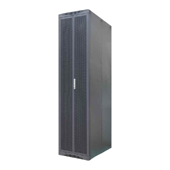
Installing the Cabinet For cabinet installation, refer to the N610E Cabinet Installation Guide (V2.0) N610E-22 Cabinet Introduction to the N610E-22 cabinet: N610E-22 cabinets are classified into single-door cabinets and double-door cabinets. The left figure shows the appearance of a double-door cabinet. The appearance of an actually delivered cabinet may be different. - Page 10 Installing the Components Inside the Cabinet Flowchart of installing the components inside the cabinet Start Take care not to stab fingers with screwdriver. Determine the position Remove the filler panels Install captive nuts Install component The procedure for installing the captive nut is as follows: Insert the lower tab of the captive nut into the square hole and hold the captive nut in position.
- Page 11 Installing the PC server (X3650M4 , X3850X5) The PC server is heavy, and two or three persons are required to carry the PC server. Determine the position in the cabinet for installing the PC server. Remove the handle bar of the front panel.
-
Page 12: Installing The Power Cables
Installing the Power Cables Guide to Installing the Power Cables (When X3650 M4 Is installed) output output input input 14 8642 23 13 7531 LANS-2 LANS-1 KVM Switch X3650 M4 -4 X3650 M4 -3 X3650 M4 -2 X3650 M4 -1 Grounding strip Grounding strip Cable No. - Page 13 Guide to Installing the Power Cables (When X3850 X5 Is installed) output output input input 19 10 5 31 11 18 9 15 13 14 12 6 4 2 LANS-1 LANS-0 X3850 X5 -3 KVM Switch X3850 X5 -2 X3850 X5 -1 X3850 X5 -0 Grounding strip Grounding strip...
- Page 14 Installing external power cables Install the power cables according to the upward cabling. Ensure that the switches of the power distribution box and power distribution cabinet are turned off before connecting the external power cables to the cabinet. •The APD32-6-24 AC PDB, installed with a three-pin connector at the input terminal block on the back, provides dual AC inputs.
- Page 15 Installing external power cables Install the power cables according to the downward cabling. Ensure that the switches of the power distribution box and power distribution cabinet are turned off before connecting the external power cables to the cabinet. • The APD32-6-24 AC PDB, installed with a three-pin connector at the input terminal block on the back, supports dual AC inputs.
- Page 16 Installing external power cables Specifications of external cables The following table lists the specifications of the cables connected to the AC power distribution cabinet. Function Electrical cable Dielectric strength 300.0 V Maximum current 36 A 227IEC10 (BVV) Type Color Black jacket (cable core: blue, brown, yellow/green) Cross-sectional area 6.00 mm^2 Default...
- Page 17 Installing Signal Cables Description of signal cables KVM (rear view) The position of each interface on the preceding devices varies with actual devices. The pictures in this document are referential to describe the installation procedure of the device. If the pictures are different from the delivered devices, take the delivered devices as the standard.
- Page 18 Description of signal cables IBM X3650M4 (rear view) IBM X3850X5 (rear view) The position of each interface on the preceding devices varies with actual devices. The pictures in this document are referential to describe the installation procedure of the device. If the pictures are different from the delivered devices, take the delivered devices as the standard.
- Page 19 Introduction to signal cables Network cable Serial cable (RJ-45 to DB-9) KVM controlling conversion cables Fiber Introduction to cable labels Connection relationships of the signal cables are marked after the commissioning of the device. Labels are attached at both ends of a cable and the ports of the server.
- Page 20 Cable connection of the X3650M4 server When connecting cables, comply with the following principle: Connecting an Ethernet interface of the server and the switch by using a network cable. Cable connection of the X3850X5 server When connecting cables, comply with the following principle: Connecting an Ethernet interface of the server and the switch by using a network cable.
- Page 21 Cable connection of the KVM The principle for connecting the cables of the Keyboard, Video, and Mouse (KVM) is as follows: Connecting the PS/S interface of the KVM and the mouse, keyboard, and VGA interface of the server by using KVM conversion power cables.
- Page 22 Laying network cables Lay network cables inside the cabinet. Lay network cables underground Lay network cables overhead between cabinet. between cabinets.
- Page 23 Laying optical fibers Lay optical fibers inside a cabinet. Lay optical fibers underground Lay optical fibers overhead between cabinets. between cabinets.
-
Page 24: Checking The Installation
Checking the Installation Checking the installation of the cabinet Item The cabinet layout complies with the engineering design. All supports are properly fixed to the floor. (This item is applicable to the installation of the ESD floor.) The support assembly is installed correctly. (This item is applicable to the installation of the ESD floor.) Each cabinet is well insulated from the support or the floor. - Page 25 Checking the installation of power cables Item All the power cables and PGND cables are copper-core cables. There are no solder joints or connectors in the power cables and the PGND cables. The extra length of power cables or PGND cables are truncated and are not coiled. There is no breaking equipment such as switches and fuses in the electrical connection of the grounding system.
- Page 26 Checking the installation of signal cables Item There are no solder joints or connectors in the signal cables. The signal cables are not scratched or broken. The connectors of the signal cables are tight and secure. Proper length of the cable is reserved at the connectors. Proper length is reserved for the signal cables at turning points.
- Page 27 Changes in Documentation Issue 01 (2012-12-31) This issue is the first official release.
- Page 28 HUAWEI TECHNOLOGIES CO., LTD. Huawei Industrial Base Bantian Longgang Shenzhen 518129 People’s Republic of China enterprise.huawei.com...