Table of Contents
Advertisement
Medium Voltage Products
HD4/HPA
Istruzioni per l'installazione e l'esercizio
Installation and service instructions
12-24 kV - 630-2000 A - 16-40 kA
Indice
11. Indicazioni per la manipolazione
degli apparecchi con SF6
Index
4
4
5
6
7
9
11
12
14
15
16
17
18
4
4
5
6
7
9
11
12
14
15
16
17
18
Advertisement
Table of Contents

Related Manuals for ABB HD4-HPA Series


Summary of Contents for ABB HD4-HPA Series
-
Page 1: Table Of Contents
Medium Voltage Products HD4/HPA Istruzioni per l’installazione e l’esercizio Installation and service instructions 12-24 kV – 630-2000 A – 16-40 kA Indice 1. Imballaggio e trasporto 2. Controllo al ricevimento 3. Magazzinaggio 4. Movimentazione 5. Descrizione 6. Istruzioni per la manovra dell'interruttore 7. - Page 3 Un comportamento responsabile Responsible behaviour safeguards your own and others’ safety! salvaguarda la vostra e l'altrui sicurezza! For any requests, please contact the Per qualsiasi esigenza contattare il Servizio Assistenza ABB. ABB Assistance Service.
- Page 4 Introduction Premessa Questa pubblicazione contiene le informazioni necessarie per This publication contains the information necessary for instal- l'installazione e la messa in servizio degli interruttori di media lation and putting into service of HD4-HPA medium voltage tensione HD4-HPA. circuit-breakers. Per il corretto impiego del prodotto se ne raccomanda una For correct usage of the product, please read this manual carefully.
- Page 5 Index Indice 1. Imballaggio e trasporto 1. Packing and transport 2. Controllo al ricevimento 2. Checking on receipt 3. Storage 3. Magazzinaggio 4. Movimentazione 4. Handling 5. Descrizione 5. Description 5.1. Generalità 5.1. General features 5.2. Reference Standards 5.2. Norme di riferimento 5.3.
-
Page 6: Imballaggio E Trasporto
If any damage or irregularity is discovered on unpacking, notify rità nella fornitura, avvertire ABB (direttamente, attraverso il ABB (directly or through the agent or supplier) as soon as rappresentante o il fornitore) il più presto possibile e in ogni possible and in any case within five days of receipt. -
Page 7: Magazzinaggio
FIG....COMANDO ... OPERATING MECHANISM -MO1 ..V -MO1 ..V Made by ABB Made by ABB Targa caratteristiche Nameplate Fig. 1 Legenda Caption A Targa caratteristiche dell’interruttore... -
Page 8: Movimentazione
4. Handling 4. Movimentazione Prima di eseguire qualsiasi operazione verificare sempre che Before carrying out any operation, always check that the le molle del comando siano scariche e l’apparecchio sia in operating mechanism springs are discharged and that the posizione di aperto. apparatus is in the open position. -
Page 9: Descrizione
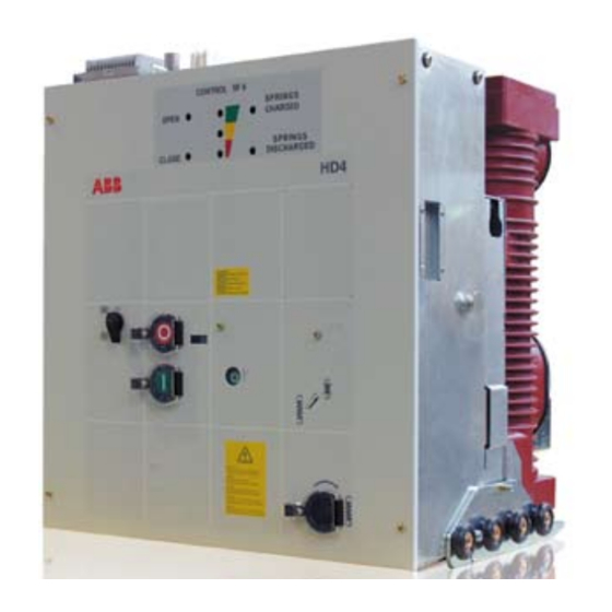
The circuit-breakers available in withdrawable version for SafeSix switchgear. 5.2. Norme di riferimento 5.2. Reference Standards Gli interruttori serie HD4-HPA sono rispondenti alle seguenti The HD4-HPA series circuit-breakers comply with the following Norme: Standards: – IEC 62271-100 – IEC 62271-100 –... - Page 10 Interruttore estraibile Withdrawable circuit-breaker. Legenda Caption 1 Dispositivo di visualizzazione aperto/chiuso 1 Device for showing open/closed 2 Dispositivo di visualizzazione dello stato della pressione del gas 2 Device for showing the state of the SF6 gas 3 Device for showing springs charged/discharged 3 Dispositivo di visualizzazione molle cariche/scariche 4 Opening pushbutton 4 Pulsante di apertura...
-
Page 11: Istruzioni Per La Manovra Dell'interruttore
6. Instructions for circuit-breaker 6. Istruzioni per la manovra operation dell'interruttore 6.1. Safety indications 6.1. Indicazioni di sicurezza HD4-HPA circuit-breakers ensure a minimum degree Gli interruttori HD4-HPA garantiscono un grado di protezione minimo IP2X se in versione estraibile, of protection IP2X if installed in withdrawable installati in quadro. - Page 12 6.3. Circuit-breaker closing 6.3. Manovre di chiusura e di apertura dell’interruttore (fig. 6) and opening operations (fig. 6) La manovra dell’interruttore può essere manuale o elettrica. Circuit-breaker operation can be manual or electrical. a) Manovra manuale di carica molle a) Manual operation for spring charging Per caricare manualmente le molle di chiusura è...
-
Page 13: Installazione
7. Installation 7. Installazione 7.1. General 7.1. Generalità Una corretta installazione è di primaria importanza. Correct installation is of prime importance. The in- structions given by the manufacturer must be care- Le istruzioni del costruttore devono essere attenta- mente studiate e seguite. È buona norma l'utilizzo fully studied and followed. -
Page 14: Messa In Servizio
All the operations regarding putting into service devono essere eseguite da personale ABB o da must be carried out by ABB personnel or personnel who are suitably qualified and have an in-depth knowl- personale che abbia una qualifica sufficiente e una edge of the apparatus and installation. - Page 15 OGGETTO DELL’ISPEZIONE PROCEDURA CONTROLLO POSITIVO SUBJECT OF THE INSPECTION PROCEDURE POSITIVE CHECK Resistenza di isolamento. Circuito di media tensione Con megger da 2500 V misurare la resistenza di isolamento La resistenza di isolamento dovrebbe es- tra fasi e massa del circuito. sere almeno 50 MΩ...
-
Page 16: Controlli Periodici
OGGETTO DELL’ISPEZIONE PROCEDURA CONTROLLO POSITIVO SUBJECT OF THE INSPECTION PROCEDURE POSITIVE CHECK Blocco a chiave (se previsto) Aprire l’interruttore. Sia la chiusura manuale che elettrica non Ruotare la chiave ed estrarla dalla sede. avvengono. Tentare la manovra di chiusura dell’interruttore. Key lock (if provided). -
Page 17: Operazioni Di Manutenzione
10. Operazioni di manutenzione 10. Maintenance operations La manutenzione deve essere eseguita da perso- Maintenance must only be carried out by ABB per- nale ABB o da personale che abbia una qualifica sonnel or in any case by suitably qualified personnel... -
Page 18: Indications For Handling Apparatus With Sf6
1VCP 000264 or 1VCP000266). chiature elettriche ed alla quantità di gas conservata nelle To dispose of the SF6 gas, please contact the ABB Assistance apparecchiature elettriche di potenza. Service (see contact persons at http://www.abb.com/ Per informazioni riguardanti la Valutazione del Ciclo di Vita ServiceGuide/alphabetical.aspx) as this operation must be... -
Page 19: Parti Di Ricambio
ABB o and maintenance must be carried out by ABB per- da personale che abbia una qualifica sufficiente e con... -
Page 20: Accessori
13. Accessories 13. Accessori 13.1. Caratteristiche degli accessori elettrici 13.1. Characteristics of electrical accessories Sganciatore di apertura (-MO1; -MO2) Shunt opening release (-MO1; -MO2) = 125 W/VA (servizio istantaneo < 45 ms) = 125 W/VA (Instantaneous service < 45 ms) = 24, 30, 48, 60, 110, 125, 220, 250 V–... - Page 21 13.2. Installation instructions 13.2. Istruzioni per l’installazione 13.2.1. Releases 13.2.1. Sganciatori Legenda Caption 1 Additional shunt opening release (YO2) 1 Sganciatore di apertura supplementare (YO2) 2 Sganciatore di apertura (YO1) 2 Shunt opening release (YO1) 3 Sganciatore di minima tensione (YU) 3 Undervoltage release (YU) 4 Sganciatore di chiusura (YC) 4 Shunt closing release (YC)
- Page 22 Prescrizioni di installazione Installation instructions Disconnettere connettore di alimentazione contrassegnato YU Disconnettere connettore di alimentazione contrassegnato dallo sganciatore di apertura minima tensione (2). YL1 per magnete di blocco (3). Disconnect the power supply connector marked YU from the Disconnect the power supply connector marked YL1 for the shunt opening undervoltage release (2).
- Page 23 Svitare vite di fissaggio supporto gruppo sganciatori. Estrarre il supporto gruppo sganciatori frontalmente al coman- Unscrew the fixing screw of the release group mount. do. Per il montaggio si procede in senso inverso. Withdraw the release group mount from the front of the operat- ing mechanism.
- Page 24 SGANCIATORE DI APERTURA YO1 YO1 SHUNT OPENING RELEASE (11) (12) (13) (10) In caso di presenza magnete di blocco Svitare quattro viti di fissaggio (13) ed YL1 svitare quattro viti di fissaggio (10) estrarre relativo sganciatore YU (12). ed estrarre magnete (11). Unscrew the four fixing screws (13) and When there is the YL1 locking magnet, withdraw the relative YU release (12).
- Page 25 SGANCIATORE DI APERTURA YO2 YO2 SHUNT OPENING RELEASE (18) (15) (19) (14) Svitare quattro viti di fissaggio bobina Svitare quattro viti di fissaggio bobina (14) ed estrarre relativa bobina YC (15). (19) ed estrarre relativa bobina YO1 (18). Unscrew the four coil fixing screws (14) Unscrew the four coil fixing screws (19) and withdraw the relative YC coil (15).
- Page 26 13.2.2. Motoriduttore 13.2.2. Geared motor Preliminary instructions Prescrizioni preliminari – Accertarsi che le molle dell’interruttore siano scariche. – Make sure that the circuit-breaker springs are discharged. – Con protezioni dell’interruttore asportate, prestare atten- – With circuit-breaker protections removed, pay attention to zione a parti in movimento.
- Page 27 Prescrizioni di installazione Installation instructions Rimuovere due viti di fissaggio micro-interruttore di finecorsa Remove the two motor limit microswitch fixing screws (2). motore (2). Sganciare molla di ritorno (3), alzare coppia nottolini di carica Release the return spring, raise the pair of charging pawls and e spingere leva in avanti (4).
- Page 28 Premere con una punta la chiavetta di collegamento situata With a bit, press the connection key located on the motor shaft sull’albero motore e ruotare la camma motore per accedere alle and turn the motor flange to access the fixing screws (5). viti di fissaggio (5).
- Page 29 13.2.3. Contatto di finecorsa motore 13.2.3. Motor limit switch Prescrizioni preliminari Preliminary instructions – Accertarsi che le molle dell’interruttore siano scariche. – Make sure that the circuit-breaker springs are discharged. – Con protezioni dell’interruttore asportate, prestare atten- – With circuit-breaker protections removed, pay attention to zione a parti in movimento.
- Page 30 Prescrizioni di installazione Installation instructions Svitare viti di fissaggio microinterruttore (2) Togliere protezione per l’alimentazione del microinterruttore Unscrew the microswitch fixing screws (2) Remove the microswitch power supply protection (3) Disconnettere collegamento microinterruttore (4) Disconnect the microswitch connection (4) PER IL MONTAGGIO CONNETTERE I FILI COME NELLA POSIZIONE ORIGINARIA (4) TO ASSEMBLE, CONNECT THE WIRES IN THEIR ORIGINAL POSITION (4)
- Page 31 13.2.4. Contatti ausiliari 13.2.4. Auxiliary contacts Gruppo da 10 contatti ausiliari Gruppo da 15 contatti ausiliari Set of 10 auxiliary contacts Set of 15 auxiliary contacts General instructions Prescrizioni generali For your safety! Per la vostra sicurezza! • Mettere in sicurezza la parte di impianto su cui si deve •...
- Page 32 Prescrizioni preliminari Preliminary instructions – Accertarsi che le molle dell’interruttore siano scariche. – Make sure that the circuit-breaker springs are discharged. – With circuit-breaker protections removed, pay attention to – Con protezioni dell’interruttore asportate, prestare atten- zione a parti in movimento. any moving parts.
- Page 33 Prescrizioni di installazione Installation instructions Disconnettere connettore di alimentazione contrassegnato Disconnettere connettore di alimentazione contrassegnato YU YL1 per magnete di blocco (3). dallo sganciatore minima tensione (2). Disconnect the power supply connector marked YU from the Disconnect the power supply connector marked YL1 for the undervoltage release (2).
- Page 34 Svitare vite di fissaggio supporto gruppo sganciatori. Estrarre il supporto gruppo sganciatori frontalmente al coman- do. Per il montaggio si procede in senso inverso. Unscrew the fixing screw of the release group mount. Withdraw the release group mount from the front of the operat- ing mechanism.
- Page 36 The data and illustrations are not binding. We reserve the right to make changes without notice in the course of technical development of the product. Copyright 2010 ABB. All rights reserved.