Panasonic GA-ML4TPoE+ Series Installation Manual
Hide thumbs
Also See for GA-ML4TPoE+ Series:
- Manual (496 pages) ,
- Manual (198 pages) ,
- Installation manual (23 pages)
Table of Contents
Advertisement
Quick Links
Installation Guide
Thank you for purchasing our product.
This document provides important information about safe and proper
operations of this Switching Hub.
Please read the "Important Safety Instructions" on pages from 3 to 6.
Any problems or damage resulting from disassembly of this Switching Hub
by customers are not covered by the warranty.
2-12-7, Higashi-Shimbashi, Minato-ku, Tokyo Japan, 105-0021
©
GA-ML4TPoE+
Model No.
2019
PN260493N-TH
PN260493N-MY
PN260493N-ID
PN260493N-SG
I1019-0
Printed in Japan
Advertisement
Table of Contents

Related Manuals for Panasonic GA-ML4TPoE+ Series


Summary of Contents for Panasonic GA-ML4TPoE+ Series
-
Page 1: Installation Guide
GA-ML4TPoE+ Installation Guide PN260493N-TH Model No. PN260493N-MY PN260493N-ID PN260493N-SG Thank you for purchasing our product. This document provides important information about safe and proper operations of this Switching Hub. Please read the "Important Safety Instructions" on pages from 3 to 6. ... -
Page 2: Table Of Contents
Contents Important Safety Instructions Basic Instructions for the Use of This Product 1 Product Outline 1.1 Features 1.2 Specifications 1.3 Accessories 1.4 Basic operation 2 Part Names and Functions 2.1 LED display change 2.2 PoE power supply function 3 Installation and Configuration 3.1 Grounding Cable Connection 3.2 Mounting on a wall 3.3 Mounting to rack... -
Page 3: Important Safety Instructions
Important Safety Instructions This chapter contains important safety instructions for preventing bodily injury and/or property damage. You are required to follow them. Severity of bodily injury and/or property damage, which could result from incorrect use of the Switching Hub, are explained below. WARNING This symbol indicates a potential hazard that could result in serious injury or death. - Page 4 WARNING Do not put the Switching Hub into fire. Deviation could lead to explosion and/or fire. Do not connect the console ports with any other console cables except for our optional PN72001 RJ45-DSub 9-pin console cable. Deviation could lead to fire, electrical shock, and/or equipment failure. ...
- Page 5 CAUTION Up to two Switching Hubs can be connected by using the connection brackets and connection bracket screws. Attach the connection brackets to the connection bracket screw holes on the front and back panels to securely fix the Switching Hubs before installation.
- Page 6 CAUTION To connect a power receiving equipment supporting IEEE802.3at to this Switching Hub, use a cable rated Cat5e or higher. Using other cables may result in heat generation, ignition, and/or equipment failure. It is strongly recommended that a lightning arrester (SPD) be installed on the twisted pair port side and the power supply side of this Switching Hub.
-
Page 7: Basic Instructions For The Use Of This Product
When Switching Hubs mounting to rack, leave a minimum of 20 mm space between them. 1. Please note that Panasonic shall not bear any liability whatsoever for any damages (this shall include lost earnings, lost opportunities, etc. but this is not restricted to these... -
Page 8: Product Outline
Product Outline GA-ML4TPoE+ is an Ethernet Switching Hub with management function having 6ports of 10/100/1000BASE-T and SFP extension slot, one of which is selectable. Ports 1 to 4 support IEEE802.3at/af PoE power supply function. 1.1 Features Ports 1 to 4 are 10/100/1000BASE-T ports corresponding to auto negotiation. Also their speed and communication mode can be switched by configuration. -
Page 9: Specifications
1.2 Specifications Interface Twisted pair port 1-4: RJ45 connector (*1) Transmitting and receiving networks system IEEE802.3 10BASE-T IEEE802.3u 100BASE-TX IEEE802.3ab 1000BASE-T Twisted pair port 5,6: RJ45 connector Transmitting and receiving networks system IEEE802.3 10BASE-T IEEE802.3u 100BASE-TX IEEE802.3ab 1000BASE-T (*1) Energy Efficient Ethernet function IEEE802.3az(LPI) SFP extension slot 5,6port Transmitting and receiving networks system... - Page 10 Product Outline Operating environment Temperature: 0–50°C, Humidity: 20–80% RH (no condensation) *If it is used beyond the operating environmental temperatures, then the protective devices will start working and the Switching Hub power will be shut off. Temperature: -20–70°C, Humidity: 10–90% RH (no condensation) Storage environment External dimensions 44 mm (Height) ×...
-
Page 11: Accessories
1.3 Accessories Please be sure to confirm the content. Please contact our distributor if any of the contents are insufficient. Quantity Installation Guide (this document) 1 (*) CD-ROM (PDF version of Operating Instructions) Rubber foot Rack mount bracket (for 19-inch rack) Screw (for 19-inch rack) Screw (for fixing the mount brackets to the Switching Hub) ... -
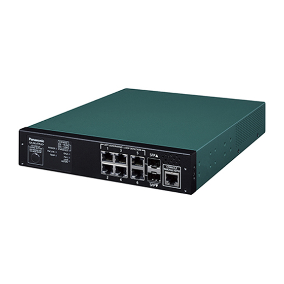
Page 12: Part Names And Functions
Part Names and Functions 10/100/1000BASE-TX ports supporting PoE power supply 10/100/1000BASE-TX ports SFP extension slot Front panel Console port Power cord hook block Back panel Power port Ground terminal Serial Number label Power port Connect the supplied power cord to this port and connect the other end into an electric outlet. - Page 13 Status/ECO mode LED GIGA mode LED DUPLEX mode LED Loop History mode LED LED Display change button Power LED PoE LIM. LED Temperature sensor LED POWER LED (Power) Green Light : Power is ON. : Power is OFF. PoE LIM. LED (PoE limit) : Supplying power in the range from 0 to 47 W.
- Page 14 Part Names and Functions Table1. Ports and Port LED lamps 1 to 6 correspond as shown below. Port LED Display mode Behavior Description Green Light Link is established. STATUS/ECO Green Blink Transmitting and receiving data. Orange Light It is shut off via the loop detection and shutoff function/storm control or the BPDU guard.
-
Page 15: Led Display Change
2.1 LED display change ●Display style set by the LED display change button Indication on the front panel and LED lamps LED display change button You can display the following items using the LED display switch button. Display for the connection with a connected terminal (Status mode), Display for the 1000 Mbps transmission rate (GIGA mode), Display for the full-duplex or half-duplex transmission system (DUPLEX mode), Display for ports with a loop history (Loop history mode),... - Page 16 Part Names and Functions Switch two types of Base modes and their LEDs in the following way: When Base mode is Status mode (factory default setting) Press "LED DISPLAY CHANGE BUTTON" manually. Automatic Boot Automatically returns to Base mode after 1 minute. Status mode DUPLEX Loop History...
-
Page 17: Poe Power Supply Function
2.2 PoE power supply function PoE power supply function operation overview Ports 1 to 4 support IEEE802.3at/af PoE. This function allows for power supply of up to 30 W through each port and 62W in total through the Switching Hub. Port LEDs (right) 1 to 4 Green Light: Supplying power normally. -
Page 18: Installation And Configuration
Installation and Configuration 3.1 Grounding Cable Connection The chassis of the equipment must be grounded properly so that the lightning can flow to the ground, which improves the capability of the chassis for resisting the electromagnetic interference. 1. Ensure that the grounding cable is connected correctly so that the equipment is protected against lightning and interference. -
Page 19: Mounting On A Wall
3.2 Mounting on a wall Use the two wall mount brackets and the eight screws (for the wall mount brackets and for connecting the main unit) which are included in the separately sold mount brackets PN71053, and connect the four holes on the sides of the Switching Hub to the four holes on the mount brackets. -
Page 20: Mounting To Rack
Installation and Configuration 3.3 Mounting to rack Use the two 19-inch rack mount brackets and eight screws (for fixing the rack mount brackets to the Switching Hub) supplied with the mount brackets to fix the mount brackets to the four holes on each side of the Switching Hub. Then securely install the Switching Hub onto the rack using the four screws (for a 19-inch rack mount) supplied with the mount brackets or the screws supplied with the rack. -
Page 21: Configuration Of Ip Address (Basic)
3.4 Configuration of IP address (Basic) (1) Connect this Switching Hub and PC with a RJ45–DSub 9-pin console cable and start up the terminal emulator (ZEQUO assist Plus, etc.). (2) Pressing Enter key once opens Login screen. Enter UserName and Password (the default is "manager"... - Page 22 Installation and Configuration 3.4 Configuration of IP address (Basic) GA-ML4TPoE+ GA-ML4TPoE+ Product Number: PN260493N Product Number: PN260493N Firmware Version: x.x.x.xx Firmware Version: x.x.x.xx MAC Address: 00:50:40:xx:xx:xx MAC Address: 00:50:40:xx:xx:xx Serial Number: xxxxxxxxxxx Serial Number: xxxxxxxxxxx UserName:manager UserName: Password:******* GA-ML4TPoE+> Screen 1 Screen 2 GA-ML4TPoE+ GA-ML4TPoE+...
-
Page 23: Troubleshooting
Troubleshooting If you find any problem, please take the following steps to check. LED The POWER LED (Power) is not lit. Check if the power cord is disconnected. Please confirm that the power cord is securely connected to the power port. ... - Page 24 Troubleshooting Communications fail. Are the equipment linked up? When the power saving mode or EEE (IEEE802.3az, Energy Efficient Ethernet ) is enabled, it may not link, depending on the connected devices. function Change the settings as per the following. 1.