Table of Contents
Advertisement
Quick Links
Advertisement
Table of Contents

Related Manuals for Panasonic GA-ML Series


Summary of Contents for Panasonic GA-ML Series
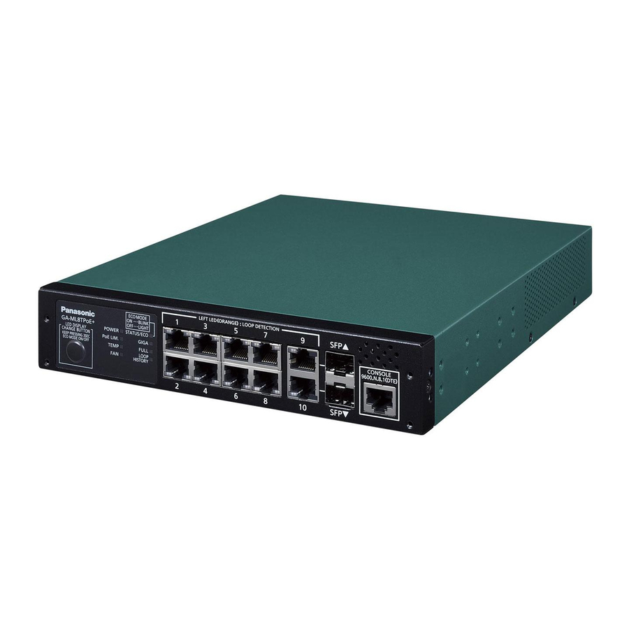
- Page 1 GA-ML Series Menu Reference Model Number PN260493N/PN260493H/ PN260496/PN260893/PN260893H/ PN260894/PN261693/PN262492/ PN262493 • Thank you for purchasing our product. • This manual provides you with important information about safe and proper operations of this Switching Hub.
- Page 2 The target model for this Menu reference is as follows Model Name Model Number Firmware Version GA-ML4TPoE+ PN260493N 3.0.0.01 and above GA-MLi4TPoE+ PN260493H 3.0.0.01 and above GA-ML4TWPoE++ PN260496 3.0.0.01 and above GA-ML8TPoE+ PN260893 3.0.0.01 and above GA-MLi8TPoE+ PN260893H 3.0.0.01 and above GA-ML8THPoE+ PN260894 3.0.0.01 and above...
-
Page 3: Table Of Contents
Table of Contents Introduction ....................6 1.1. Connecting to a Console Port ..............7 Configuration ..................... 8 2.1. Log-in ....................8 2.2. Basic Operation on the Screen ............. 10 2.3. Switching to the Menu Screen ............. 12 2.4. Main Menu ..................13 2.5. - Page 4 4.1.3. VLAN Modification Menu ............. 74 4.1.4. VLAN Port Configuration Menu ............ 76 4.1.5. Hybrid VLAN Configuration Menu ..........78 4.1.6. Trunk VLAN Configuration Menu ..........80 4.1.7. Access VLAN Configuration Menu ..........82 4.2. Link Aggregation .................. 84 4.2.1. Link Aggregation: ................. 84 4.2.2.
- Page 5 4.10.4. RRP Domain Information ............155 4.11.1. Loop Detection Configuration Menu .......... 157 4.11.2. Loop History Information ............160 4.12.1. PPS Configuration ..............161 4.12.2. PPS Notification Configuration ........... 164 4.12.3. PPS Port Configuration ............... 166 4.12.4. PPS Neighbor Table ..............168 4.12.5.
-
Page 6: Introduction
1. Introduction After turning on the power of this device, it operates as a normal switching hub. To use a function of SNMP management and the specific function, the configura- tions such as a console port, Telnet, and SSH are needed. This part describes the configuration of the device. -
Page 7: Connecting To A Console Port
1.1. Connecting to a Console Port Connect a terminal, where a terminal emulator operates, to a console port of the RJ 45 model of this device. The terminal includes the asynchronous terminal pro- duced by DEC and the hyper terminal (which is included in the Windows XP or ear- lier version). -
Page 8: Configuration
2. Configuration 2.1. Log-in After connecting to a console port, the appearance of the command prompt becomes the log-in screen as Figure 2-1. Check the communication settings if the log-in screen is not displayed. GA-MLxxTPoE+ Command Line Interface Product Number: PNxxxxxx Firmware Version: V2.0.1.00 MAC Address: 00:50:40:xx:xx:xx Serial Number: xxxxxxxxxxx... - Page 9 Do the following procedure on the screen. ① Type “manager” on a user-name column, and then press Enter. Log-in name as Figure 2-1: The log-in name is set to “manager” for the factory default settings. ② As Figure 2-1, type “manager” on a password column, and then press Enter.
-
Page 10: Basic Operation On The Screen
2.2. Basic Operation on the Screen Each screen of this device consists of the following configuration. 1. Subject 2. Name of Upper menu 3. Name of a current Menu PNxxxxxx Local Management System Basic Switch Configuration -> System IP Configuration Menu MAC Address: xx:xx:xx:xx:xx:xx IP Address:... - Page 11 Screen Description Subject This is the subject of this screen. “Local Management System” is dis- played when you access from a console. Also,“Remote Management System” is displayed when accessing by using Telnet. Name of the Displays the name of the upper menu. Press Q (command) of the fol- Upper Menu lowing to move to the menu screen, which is displayed on this col- umn.
-
Page 12: Switching To The Menu Screen
2.3. Switching to the Menu Screen Log into the section 2 to operate this section. ① Enter (or type) “enable” as Figure 2-4 (Switching to the Menu Screen), and then the appearance of “GA-MLxxTPoE+>” becomes “GA-MLxxTPoE+#”. ② Type Menu as Figure 2-4 (Switching to the Menu Screen). ③... -
Page 13: Main Menu
2.4. Main Menu After you log-in, the appearance of the command prompt becomes the Main Menu as Figure 2-6. The Main Menu of this device consists of the Main Menu and Sub menu, and has a tree structure, centering the Main Menu. Enter the command characters to move to the sub menu, and then press Q (command) to return to the top menu. -
Page 14: General Information Menu
2.5. General Information Menu Press G at the command (prompt) on the Main Menu, and then you can see the General Information Menu as Figure 2-7. The screen allows you to browse the information on this device. In addition, this screen is used to display the content, only. - Page 15 Screen Description System up for Displays the total time from starting up (or activating) this device. Boot / Runtime Displays a version of firmware of this device. This indicates a version; the left side Code Version is Boot Code, and the right side is Runtime Code. (The upgrade of firmware described on the section 6.1 becomes the upgrade of Runtime Code.)...
-
Page 16: Save Configuration To Flash
2.6. Save Configuration to Flash Press F on the Main Menu, and then you can see “Save Configuration to Flash” as Figure 2-8. Select this command to save the content, which is configured on this device, on the built-in memory. The appearance of the command prompt becomes “Save current configuration?(Y/N)”... - Page 17 PNxxxxxx Local Management System Main Menu -> Save Configuration to Flash Saving configuration to flash is successful, press any key to continue... Figure 2-8 B: Saving the Configuration Information: Exiting to Save...
-
Page 18: Command-Line Interface (Cli)
2.7. Command-line Interface (CLI) Press C (command) on the Main Menu, and then the appearance of the screen becomes as Figure 2-10. You can configure on a command line instead of the menu format from this screen. See the configuration method as it is described on “Operation manual (CLI). -
Page 19: Log Out
2.8. Log Out Press Q (command) on the Main Menu, and then the screen returns to the log-in screen when accessing from a console. In addition, accessing through Telnet or SSH is disconnected. Do the procedure for logging in the 2nd section to operate again. -
Page 20: Basic Switch Configuration
3. Basic Switch Configuration Press B (command) on the Main Menu, and then you can see the Basic Switch Configuration menu as Figure 3-1. This screen allows you to configure the IP address, SNMP, a port configuration, a spanning tree, and an access control (or limitation). -
Page 21: System Ip Configuration
3.1. System IP Configuration Press I (command) on the Basic Switch Configuration menu, and then you can see the System IP Configuration Menu as Figure 3-2. You can configure "the IP address of this device" on this screen. PNxxxxxx Local Management System Basic Switch Configuration ->... - Page 22 The following describes commands to be used on this screen. Configures and changes the IP address. Press I (command), and then the appearance of the command prompt becomes "Enter IP address>". After that, enter the IP address of the switch. Configures and changes the subnet-mask.
-
Page 23: Snmp Configuration
3.2. SNMP Configuration Press N (command) on the Basic Switch Configuration menu, and then you can see the SNMP Configuration menu as Figure 3-3. You can configure as SNMP agent on this screen. PNxxxxxx Local Management System Basic Switch Configuration -> SNMP Configuration Menu SNMP [M]anagement Configuration SNMP [T]rap Receiver Configuration [Q]uit to previous menu... -
Page 24: Snmp Management Configuration
3.2.1. SNMP Management Configuration Press M (command) on the SNMP Configuration menu, and then you can see SNMP Management Configuration Menu as Figure 3-4. You can configure the com- munity name of SNMP manager on this screen. See the section 3.5, and change the configuration of SNMP Agent to Enable in advance when configuring the community name of SNMP manager. - Page 25 The following describes commands to be used on this screen. Configures the status of SNMP manager. 1. Press S (command), and then the appearance of the command prompt becomes “Enter manager entry number>”. After that, enter the entry number of SNMP manager to con- figure.
-
Page 26: Snmp Trap Receiver Configuration Menu
3.2.2. SNMP Trap Receiver Configuration Menu Press T (command) on the SNMP Configuration Menu, and then you can see SNMP Trap Receiver Configuration Menu as Figure 3-5. You can configure to transmit SNMP traps on this screen. See the section 3.2.1 when configuring privilege (Read- Write/Read-Only) of the destination of SNMP traps. - Page 27 The following describes commands to be used on this screen. Configures to enable or disable a trap-destination. 1. Press S (command), and then the appearance of the command prompt becomes “Enter manager entry number>. After that, enter the entry number of the trap-destination to be configured.
-
Page 28: Enable/Disable Individual Trap Menu
3.2.3. Enable/Disable Individual Trap Menu Press D (command) on the screen of the SNMP Trap Receiver Configuration, and then you can see Enable/Disable Individual Trap Menu as the screen 2.7-7. You can configure to send traps on this screen. PNxxxxxx Local Management System SNMP Trap Receiver Configuration ->... - Page 29 Coldstart Displays the configuration of enabling and disabling trap-transmission when the Trap Control device operates Cold-starting. Enabled Enables the trap-transmission. Disabled Disables the trap-transmission (factory default settings). Warmstart Displays the configuration of enabling and disabling trap-transmission when the Trap Control device operates warm-start.
-
Page 30: Port Configuration (Basic Menu)
3.3. Port Configuration (Basic Menu) Press P (command) on the Basic Switch Configuration menu, and then you can see Port Configuration Menu as Figure 3-7. You can display the condition of each port, and configure the ports on this screen. PNxxxxxx Local Management System Port Configuration ->... - Page 31 Screen Description Port Displays the port-number. Trunk Displays the configuration condition of trunking by the group number. Type Indicates the type of ports. 100TX Indicates 10/100BASE-TX. 1000T Indicates 10/100/1000BASE-T. 10G-T Indicates 100/1000/10GBASE-T. 10G-R Indicates SFP+ ports. Admin Displays the condition of a current port. All of the factory default settings are set to "Enabled".
- Page 32 The following describes commands to be used on this screen. Displays the next page. Press N (command) to display the next page. Displays the previous page. Press P (command) to display the previous page. Each port can be set to enabled or disabled. 1.
- Page 33 ------------------------------------------------------------------------------------------------------------------------------------------- Note: This screen displays the condition of the ports, which are not updated automati- cally. Enter a key randomly to display the latest condition . -------------------------------------------------------------------------------------------------------------------------------------------...
-
Page 34: Port Configuration Power Saving Menu
3.4. Port Configuration Power Saving Menu You can reduce the power consumption on this device by detecting the connection status of port(s), by using the power-saving mode of our original function to adjust (or control) the power consumption to the necessary amount during the disconnection, and by using the Energy Efficient Ethernet (EEE) of IEEE802.3az, respectively. - Page 35 Mode Displays the configuration status of full or half duplex, and the communication speed. Every mode is set to “Auto” for the factory default settings. Auto Auto negotiation mode 100-FDx(100F) 100Mbps full duplex 100-HDx(100H) 100MBps half duplex 10-FDx(10F) 10Mbps full duplex 10-HDx(10H) 10MBps half duplex Power-Saving...
-
Page 36: System Security Configuration
3.5. System Security Configuration Press S (command) on the Basic Switch Configuration menu, and then you can see “System Security Configuration” as Figure 3-9. You can perform configuration tasks when accessing this device for configuringand managing on this screen. PNxxxxxx Local Management System Basic Switch Configuration ->... - Page 37 Displays if the access with the software of the IP address configuration, which is Interface included in a network camera produced by Panasonic and “ZEQUO assist Plus” as a support tool of our switching hub, is possible. The factory default setting is “Enabled”.
- Page 38 The following describes commands to be used on this screen. Configures time needed to disconnect automatically if nothing is entered when a console is con- nected. Press C (command), and then the appearance of the command prompt becomes “Enter console idle timeout>”. Configure the (numerical) value between 0 and 60 (minutes). If 0 is configured, automatic disconnection is not operated.
- Page 39 Configures the location of checking a user name and a password when logging in. 1. Press O (command), and then the appearance of the command prompt becomes “Input Login Methd 1 >”. Enter the method of logging in of Login Method 1. Enter the user-name, which is configured with equipment, and L to use a password.
-
Page 40: Telnet Access Limitation Configuration
3.5.1. Telnet Access Limitation Configuration Press A (command) on the screen of System Security Configuration, and then you can see Telnet Access Limitation Menu as Figure 3-10. You can perform the limita- tion configuration of equipment (or device) that accesses this device through Telnet, on this screen. - Page 41 Configures an IP address to allow. Five ranges can be configured. 1. Press A (command), and then the appearance of the command prompt becomes "Enter IP address entry number>". After that, enter the entry number in the range from 1 to 5. 2.
-
Page 42: Radius Configuration
3.5.2. RADIUS Configuration Press R (command) on the screen of the System Security Configuration, and then you can see RADIUS Configuration Menu as Figure 3-11. You can configure the access to the RADIUS server, which is used for the IEEE802.1X authentication on this screen. - Page 43 Configures the NAS ID. Press A (command), and then the appearance of the command prompt becomes “Enter NAS ID>”. After that, enter the NAS ID within 16 characters (half-size). Configures the IP address of the RADIUS server. 1. Press M (command), and then the appearance of the command prompt becomes “Enter RADIUS server index>”.
-
Page 44: Syslog Transmission Configuration
3.5.3. Syslog Transmission Configuration Press G (command) on the screen of the System Security Configuration, and then you can see Syslog Transmission Configuration Menu as Figure 3-12. You can configure Syslog servers as the destination of transmitting system-log on this screen. - Page 45 Configures an IP address of the Syslog server. Press I (command), and then the appearance of the command prompt becomes “Enter IP address for manager>. After that, enter the IP address of the Syslog server. The IP address is assigned automatically from No.1. The IP address of Syslog server can be configured up to four.
-
Page 46: Ssh Server Configuration
3.5.4. SSH Server Configuration Press H (command) on the screen of the System Security Configuration, and then you can see “SSH Server Configuration” as Figure 3-13. You can configure the SSH servers on this screen. This device supports SSHv2, only. Use a client that sup- ports the SSHv2 to connect. - Page 47 The following describes commands to be used on this screen. Configures to become accessible with SSH. Press H (command), and then the appearance of the command prompt becomes “Enable or Disable SSH server (E/D)>”. Press E to become accessible, and D to become inaccessible. Configures time needed until the connection is disconnected automatically if nothing is entered when connecting with the SSH.
-
Page 48: Led Base Mode Configuration
3.5.5. LED Base Mode Configuration Press B (command) on the screen of the System Security Configuration, and then you can see the LED Base Mode Configuration as Figure 3-14. You can configure the LED base mode on this screen. PNxxxxxx Local Management System System Security Configuration ->... -
Page 49: Forwarding Database
3.6. Forwarding Database Press F (command) on the Basic Switch Configuration menu, and then you can see the Forwarding Database Menu as Figure 3-15. The list of a MAC address table learned and stored (which is necessary for transferring packets) is displayed on this screen. -
Page 50: Static Address Table
3.6.1. Static Address Table Press S (command) on the Forwarding Database menu, and then you can see Static Address Table Menu as Figure 3-16. You can add or delete a MAC address stati- cally, on this screen. PNxxxxxx Local Management System Forwarding Database Menu ->... -
Page 51: Mac Learning Menu
3.6.2. MAC Learning Menu Press A (command) on the Forwarding Database Menu, and then you can see the MAC Learning Menu as Figure 3-17. You can configure the learning mode for MAC address per Port, on this screen. PNxxxxxx Local Management System Forwarding Database Menu ->... - Page 52 ------------------------------------------------------------------------------------------------------------------------------------------- Note: When receiving frames with a new source MAC address that does not learn on the condition that the MAC address of a limit value is learned already. To use the limit value, the auto learning for MAC address needs to be enabled. A static MAC address is not included in the target of the limit value.
-
Page 53: Display Mac Address By Port
3.6.3. Display MAC Address by Port Press P (command) on the Forwarding Database Menu, and then the appearance of the command prompt becomes “Enter port number>”. Specify the port- number, and then you can see “Display MAC Address by Port” as Figure 3-18. You can display a MAC address table per port on this screen. -
Page 54: Display Mac Address By Mac
3.6.4. Display MAC Address by MAC Press M (command) on the Forwarding Database Menu, and then you can see “Display MAC Address by MAC” as Figure 3-19. This screen can display all of the MAC address tables of this device. PNxxxxxx Local Management System Forwarding Database Menu ->... -
Page 55: Display Mac Address By Vlan Id
3.6.5. Display MAC Address by VLAN ID Press V (command) on the Forwarding Database Menu, and then the appearance of the command prompt becomes “Enter VLAN ID>”. Designate the port-num- ber, and then you can see “Display MAC Address by VLAN ID” as Figure 3-20. This screen can also display a MAC address table per VLAN. -
Page 56: Time Configuration
3.7. Time Configuration This device allows you to configure the time accurately by having the synchroniza- tion of an external SNTP server and the built-in clock and the support of the time configuration and SNTP (Simple Network Time Protocol). Press T (command) on the Basic Switch Configuration menu, and then you can see Time Configuration Menu as Figure 3-22. - Page 57 PNxxxxxx Local Management System Basic Switch Configuration -> Time Configuration Menu Current Time Source :xxxx.com Time ( HH:MM:SS ) : xx:xx:xx Date ( YYYY/MM/DD ) : xxxx/xx/xx xxxxxx Time Zone : UTC +09 : 00 Daylight Saving Time : Disabled -------------------------------- <COMMAND>...
- Page 58 The following describes commands to be used on this screen. Configures the time of the built-in clock of this device. 1. Press C (command), and then the appearance of the command prompt becomes "Enter Date(Year) >". Enter the year for that. 2.
-
Page 59: Sntp Configuration Menu
3.7.1. SNTP Configuration Menu Select P (command) on the Time Configuration menu, and then you can see the SNTP server Menu as screen 2.7-21. You can configure SNTP servers on this screen. PNxxxxxx Local Management System Time Configuration Menu -> SNTP Configuration Menu SNTP State : Disabled Interval : 720 seconds... - Page 60 The following describes commands to be used on this screen. Configures the SNTP status. Press S (command), and then the appearance of the command prompt becomes “Enable or Disable (E/D)>”. After that, Press E to enable and D to disable. Configures the interval of time synchronization with SNTP servers.
-
Page 61: Arp Table
3.8. ARP Table Press R (command) on the Basic Switch Configuration menu to display the ARP Table screen, as illustrated in the Figure 3-24. You can see and configure ARP table on this screen. PNxxxxxx Local Management System Basic Switch Configuration -> ARP Table ARP Age Timeout : 240 seconds IP Address Hardware Address... - Page 62 The following describes commands to be used on this screen. Displays the next page. Press N (command) to display the next page. Displays the previous page. Press P (command) to display the previous page. Configures the aging time out on ARP table. Press T (command).
-
Page 63: Neighbor Table
3.9.1. Neighbor Table Press E (command) on the screen of the LLDP Configuration, and then you can see “Neighbor Table” as Figure 3-25. You can display the Neighbor table on this screen. PNxxxxxx Local Management System LLDP Configuration -> Neighbor Table Total Neighbors: Chassis ID Port ID... -
Page 64: Lldp Configuration
3.9.2. LLDP Configuration Press L (command) on the Basic Switch Configuration menu, and then you can see "LLDP Configuration" as Figure 3-26. You can perform LLDP configuration on this screen. PNxxxxxx Local Management System Basic Switch Configuration -> LLDP Configuration LLDP Status : Disabled Port Admin Status Port Desc Sys Name Sys Desc Sys Cap Mgmt Addr... - Page 65 Sys Cap Displays if the system capability (or function) information is included in the LLDP frame. Enabled Includes in the LLDP. Disabled Does not include in the LLDP (factory default settings ). Mgmt Addr Displays if the IP address of system(s) is included in the LLDP frame. Enabled Includes in the LLDP.
-
Page 66: Neighbor Detailed Information
3.9.3. Neighbor Detailed Information Press D (command) on the screen of the Neighbor table, and then you can see “Neighbor Detail Information” as Figure 3-27. This screen displays the details of Neighbor Table. Use the UTP cable in that case. PNxxxxxx Local Management System Neighbor Table ->... -
Page 67: Advanced Switch Configuration
Advanced Switch Configuration Press A (command) on the Main Menu, and then you can see Advanced Switch Configuration Menu as Figure 4-1. This screen configures the VLAN, link aggrega- tion. port monitoring, QoS, a spanning tree, storm control, IGMP snooping, Power Over Ethernet, ring protocol, the function of detecting and blocking a loop, port grouping, DDM, and the PPS function that this device includes. - Page 68 Screen Description VLAN Management Performs the VLAN configuration. Link Aggregation Configures a link aggregation. Port Monitoring Configures a port monitoring. Configuration Multiple Spanning Tree Configures a spanning tree. Configuration Quality of Service Performs the QoS configuration. Configuration Storm Control Configures the function of a storm control. Configuration IGMP Snooping Configures IGMP Snooping.
-
Page 69: Vlan Management (Vlan Configuration)
4.1. VLAN Management (VLAN Configuration) 4.1.1. VLAN Management Press V (command) on the Advanced Switch Configuration menu, and then you can see VLAN Management Menu as Figure 4-2. You can configure VLAN on this screen. PNxxxxxx Local Management System Advanced Switch Configuration -> VLAN Management Menu GVRP Status : Disabled Maximum VLANs : 4,094... - Page 70 ------------------------------------------------------------------------------------------------------------------------------------------- Note: V LAN ID=1 is configured to the factory default settings. All the ports belong to this VLAN, and the management VLAN is configured on VLAN ID1 (default VLAN). ------------------------------------------------------------------------------------------------------------------------------------------- The following describes commands to be used on this screen. Displays the next page.
- Page 71 Note: The following restriction/limiting condition is defined (or determined) when enabling the Internet mansion mode. Be sure to check the following contents. (1)Using with a spanning tree function is not allowed. (2)Using with a function of IGMP snooping is not allowed. (3)Using with the function of a link-aggregation is not allowed.
-
Page 72: Vlan Creation Menu
4.1.2. VLAN Creation Menu Press C (command) on the VLAN Management menu, and then you can see VLAN Creation Menu as Figure 4-3. You can create VLAN on this screen. PNxxxxxx Local Management System VLAN Management -> VLAN Creation Menu VLAN ID VLAN Name -------------------------------- <COMMAND>... - Page 73 The following describes commands to be used on this screen. Configures VLAN ID. Press V (command), and then the appearance of the command prompt becomes "Enter VLAN ID >". After that, enter a new VLAN ID. Configures VLAN name. Press N (command), and then the appearance of the command prompt becomes “Enter VLAN name >”.
-
Page 74: Vlan Modification Menu
4.1.3. VLAN Modification Menu Press O (command), and then the appearance of the command prompt becomes the VLAN Management Menu. Designate a target VLAN ID, and then you can see the VLAN Modification Menu as Figure 4-4. You can change the configuration information on VLAN on this screen. - Page 75 The following describes commands to be used on this screen. Changes the VLAN name. Press N (command), and then the appearance of the command becomes “Enter VLAN name >”. Enter the VLAN name using characters: within the half-size of 32 characters. Configures the VLAN.
-
Page 76: Vlan Port Configuration Menu
4.1.4. VLAN Port Configuration Menu Press S (command) on the VLAN Management menu, and then you can see VLAN Port Configuration Menu as Figure 4-5. You can perform the configuration per VLAN port on this screen. PNxxxxxx Local Management System VLAN Management ->... - Page 77 The following describes commands to be used on this screen. Displays the next page. Press N (command) to display the next page. Displays the previous page. Press P (command) to display the previous page. Configures the type of the administrative mode. Enter the port-number to be changed.
-
Page 78: Hybrid Vlan Configuration Menu
4.1.5. Hybrid VLAN Configuration Menu Press H (command) on the VLAN Management menu, and then you can see Hybrid VLAN Configuration Menu as Figure 4-6. You can configure the Hybrid VLAN per port on this screen. PNxxxxxx Local Management System VLAN Management ->... - Page 79 The following describes commands to be used on this screen. Displays the next page. Press N (command) to display the next page. Displays the previous page. a Press P (command) to display the previous page. Configures the PVID. Press V, and then the appearance of the command prompt becomes “Enter port- number>”.
-
Page 80: Trunk Vlan Configuration Menu
4.1.6. Trunk VLAN Configuration Menu Press T (command) on the VLAN Management menu, and then you can see Trunk VLAN Configuration Menu as Figure 4-7. You can configure Trunk VLAN per port on this screen. PNxxxxxx Local Management System VLAN Management -> Trunk VLAN Configuration Menu Port Trunking Native VLAN Trunking VLANs (Inactive) GVRP... - Page 81 The following describes commands to be used on this screen. Displays the next page. Press N (command) to display the next page. Displays the previous page. Press P (command) to display the previous page. Configures Trunking Native VLAN. Press V, and then the appearance of the command prompt becomes “Enter port- number>”.
-
Page 82: Access Vlan Configuration Menu
4.1.7. Access VLAN Configuration Menu Press A (command) on the VLAN Management menu, and then you can see Access VLAN Configuration Menu as Figure 4-8. This screen allows you to configure an Access VLAN per port. PNxxxxxx Local Management System VLAN Management ->... - Page 83 The following describes commands to be used on this screen. Displays the next page. Press N (command) to display the next page. Displays the previous page. Press P (command) to display the previous page. Configures the VLAN ID of the access mode. Press A (command) and then the appearance of the command prompt becomes “Enter port-number>”.
-
Page 84: Link Aggregation
4.2. Link Aggregation 4.2.1. Link Aggregation: A link aggregation groups two or more ports of the switch, and is the function of connecting between the ports, which are grouped to increase the communication bandwidth between switches. Using the function of the link aggregation is called a Trunking. -
Page 85: Trunk Configuration Menu
4.2.2. Trunk Configuration Menu Press L (command) on the Advanced Switch Configuration menu, and then you can see Trunk Configuration Menu as Figure 4-9. You can configure a trunking on this screen. PNxxxxxx Local Management System Advanced Switch Configuration -> Trunk Configuration Menu System Priority : 32768 Mode... - Page 86 The following describes commands to be used on this screen. Displays the next page. Press N (command) to display the next page. Displays the previous page. Press P (command) to display the previous page. Sets the value of System Priorityof this device on LACP. Press T (command), and then the appearance of the command prompt becomes “Enter system priority for LACP>”.
-
Page 87: Set Port Priority
4.2.3. Set Port Priority Press O (command) on the Trunk Configuration menu, and then you can see “Set Port Priority” as Figure 4-10. You can implement a priority configuration for trunk- ing on this screen. PN262492 Local Management System Trunk Configuration Menu -> Set Port Priority System Priority : 32768 System ID... -
Page 88: Set Port Priority
4.2.4. Set Port Priority Press G (command) on the Trunk Configuration Menu, and then you can see “LACP Status” as Figure 4-11. You can check the status of LACP group on this screen. (The status can be displayed for only keys whose mode is “Active” or “Passive”.) PNxxxxxx Local Management System Trunk Configuration Menu ->... -
Page 89: Port Monitoring Configuration
4.3. Port Monitoring Configuration Press M (command) on the Advanced Switch Configuration menu, and then you can see Mirror Consfiguration Menu as Figure 4-12. Filtering is applied on this device when analyzing the communication (e.g. protocol analyzer), and monitor- ing packets between other ports that cannot be obtained normally is possible. You can configure a port-monitoring on this screen. - Page 90 The following describes commands to be used on this screen. Configures the ID of a remote VLAN. 1. Press V (command), and then the appearance of the command prompt becomes “Seletct source or destination remote vlan (S/D)>”. Press S to configure the Remote VLAN of the source session, and D to configure the Remote VLAN of the destination session.
-
Page 91: Multiple Spanning Tree Configuration
4.4.1. Multiple Spanning Tree Configuration Press S (command) on the Advanced Switch Configuration menu, and then you can see “Multiple Spanning Tree Configuration” as Figure 4-13 A. This device supports three versions: a multiple spanning tree protocol that is compliant with IEEE802.1s (MSTP: Figure 4-13B), a rapid spanning tree protocol compatible with IEEE802.1w, (RSTP: Figure 4-13C), and a span- ning tree protocol compatible with IEEE802.1D (STP: Figure 4-13 D). - Page 92 PNxxxxxx Local Management System Advanced Switch Configuration -> Multiple Spanning Tree Configuration Global MSTP Status: Enabled Global Protocol Version : MSTP Global MST Configuration Name Global MST Revision Level Global MST Config Digest : 00000000000000000000000000000000 -------------------------------- <COMMAND> ----------------------------------- [E]nable/Disable Global MSTP CIST [B]asic Port Configuration Set MSTP Protocol [V]ersion CIST [A]dvanced Port Configuration...
- Page 93 PNxxxxxx Local Management System Advanced Switch Configuration -> Multiple Spanning Tree Configuration Global MSTP Status: Enabled Global Protocol Version : STP-Compatible Global MST Configuration Name Global MST Revision Level Global MST Config Digest : 00000000000000000000000000000000 -------------------------------- <COMMAND> ----------------------------------- [E]nable/Disable Global MSTP CIST [B]asic Port Configuration Set MSTP Protocol [V]ersion CIST [A]dvanced Port Configuration...
- Page 94 The following describes commands to be used on this screen. Configures ON/OFF of a spanning tree protocol. Press E (command), and then the appearance of the command prompt becomes “Enable or Disable STP (E/D)>”. After that, press E to use it, and D otherwise. Configures the operation mode of a spanning tree protoco.
-
Page 95: Cist Configuration
4.4.2. CIST Configuration Press C (command) on the Multiple Spanning Tree Configuration menu to display the screen of the CIST Configuration, as illustrated in the Figure 4-17. The follow- ing screen configures a basic configuration of CIST. PNxxxxxx Local Management System Multiple Spanning Tree Configuration ->... - Page 96 CIST Bridge Forward Delay Displays Forward Delay when this device becomes a route bridge. Max Hop Count Displays the maximum number of Hop. (The value determined by a route bridge is displayed.) ------------------------------------------------------------------------------------------------------------------------------------------- Note: This device cannot be used in the combination of a spanning tree and link aggregation.
-
Page 97: Cist Basic Port Configuration
4.4.3. CIST Basic Port Configuration Press B (command) on the Multiple Spanning Tree Configuration, and then you can see “CIST Basic Port Configuration” as Figure 4-18. You can perform a CIST basic port configuration on this screen. PNxxxxxx Local Management System Multiple Spanning Tree Configuration ->... - Page 98 STP Status Displays either disabled or enabled condition of a spanning tree on each port. Enabled A spanning tree is enabled. Disabled A spanning tree is disabled. Guard Displays the enable or disable a condition of BPDU guard on each port. It is set to “Disabled”...
-
Page 99: Cist Advanced Port Configuration
4.4.4. CIST Advanced Port Configuration Press A (command) on the Multiple Spanning Tree Configuration menu to display the screen of “CIST Advanced Port Configuration” as Figure 4-19. You can per- form the advanced configuration of CIST ports on this screen. PNxxxxxx Local Management System Multiple Spanning Tree Configuration ->... - Page 100 Admin/ Displays if this device is connected as Point-to-Point. OperPtoP The first half (Admin:Administration) displays (or shows) configured condition. The latter half (Oper:Operation) displays the actual condition. Auto Recognizes automatically depending on a port condition (Only Admin) True P-to-P (network) is connected. False P-to-P (network) is not connected.
-
Page 101: Mstp Instance Configuration
4.4.5. MSTP Instance Configuration Press T (command) on the Multiple Spanning Tree Configuration menu, and then you can see “MSTP Instance Configuration” as Figure 4-20. You can configure the instance of a spanning tree on this screen. PNxxxxxx Local Management System Multiple Spanning Tree Configuration ->... - Page 102 Deletes the MST instance ID. Press R (command), and then the appearance of the command prompt becomes "Enter MSTP instance ID>". Enter the MST instance ID to delete. M Configures the MST instance. 1. Press M (command), and then the appearance of the command prompt becomes "Enter MSTP instance ID>", enter the instance ID of target MST.
-
Page 103: Mst Instance Configuration
4.4.6. MST Instance Configuration Press M (command) and MST instance ID on the screen of MSTP Instance Configuration, and then you can see “MST Instance Configuration” as Figure 4- 21. You can perform the advanced settings regarding the MST instance on this screen. -
Page 104: Mst Instance Port Configuration
4.4.7. MST Instance Port Configuration Press C (command) and MSTP Instance ID on the screen of the MSTP Instance Configuration, and then you can see “MST Instance Port Configuration” as Figure 4-22. You can configure the port regarding MST instance, on this screen. PNxxxxxx Local Management System MSTP Instance Configuration ->... - Page 105 Role Displays the port role on a spanning tree. Designated In operation as a designated port. Root In operation as a route port. Alternate In operation as an alternate port. Backup In operation as a backup port. Disabled STP is not in operation. Indicates the status that a port is not associated with MST instance selected.
-
Page 106: Mst Instance Topology Information
4.4.8. MST Instance Topology Information Press I (command) and MSTP instance ID on the screen of the MSTP Instance Configuration, and then you can see “MST Instance Topology Information” as Figure 4-23. This screen displays the configuration information on MST instance. PNxxxxxx Local Management System MST Instance Configuration ->... -
Page 107: Designated Topology Information (1-3-5-C)
4.4.9. Designated Topology Information (1-3-5-c) Press I (command) on the Multiple Spanning Tree Configuration menu, and then you can see “Designated Topology Information” as Figure 4-24. This screen dis- plays the configuration information on a spanning tree per port. PNxxxxxx Local Management System Multiple Spanning Tree Configuration ->... -
Page 108: Regional Topology Information
4.4.10. Regional Topology Information Press G on the Multiple Spanning Tree Configuration menu, and then you can see “Regional Topology Information” as Figure 4-25. This screen displays the configu- ration information on a spanning tree per port. PNxxxxxx Local Management System Multiple Spanning Tree Configuration ->... -
Page 109: Quality Of Service Configuration
4.5.1. Quality of Service Configuration Press U (command) on the Advanced Switch Configuration Menu, and then you can see Quality of Service Configuration Menu as Figure 4-26. You can configure the QoS (Quality of Service) of this device, on this screen. PNxxxxxx Local Management System Advanced Switch Configuration Menu ->... -
Page 110: Traffic Class Configuration
4.5.2. Traffic Class Configuration Press T (command) on the Quality of Service Configuration menu, and then you can see “Traffic Class Configuration” as Figure 4-27. You can configure QoS and a traffic class on this screen. PNxxxxxx Local Management System Quality of Service Configuration ->... -
Page 111: Scheduling Method
4.5.3. Scheduling Method Press C (command) on the Traffic Class Configuration menu, and then you can see “Scheduling Method” as Figure 4-28. You can configure the scheduling method on this screen. PNxxxxxx Local Management System Quality of Service Configuration -> Scheduling Method Selected port-number : 1 Scheduling Method: Weighted Round Robin QID Weights... - Page 112 Returns to the top menu.
-
Page 113: Egress Rate Limiting Configuration
4.5.4. Egress Rate Limiting Configuration Press E (command) on the Quality of Service Configuration menu, and then you can see Egress Rate Limiting Configuration Menu as Figure 4-29. This screen allows you to configure the control of the bandwidth. PNxxxxxx Local Management System Quality of Service Configuration ->... - Page 114 The following describes commands to be used on this screen. Displays the next page. Press N (command) to display the next page. Displays the previous page. Press P (command) to display the previous page. Configures a bandwidth. 1. Press B (command), and then the appearance of the command prompt becomes "Enter port-number>B".
-
Page 115: Storm Control Configuration Menu
4.6. Storm Control Configuration Menu Press O (command) on the Advanced Switch Configuration menu, and then you can see Storm Control Configuration Menu as Figure 4-30. You can configure each storm control of Unknown unicast and Broadcast Multicast on this screen. PNxxxxxx Local Management System Advanced Switch Configuration ->... - Page 116 The following describes commands to be used on this screen. Displays the next page. Press N (command) to display the next page. Displays the previous page. Press P (command) to display the previous page. Set the threshold of Unicast. 1. Press D (command), and then the appearance of the command prompt becomes “Enter port-number>”.
-
Page 117: Igmp Snooping Configuration
4.7. IGMP Snooping Configuration Press I (command) on the Advanced Switch Configuration menu, and then you can see “IGMP Snooping Configuration” as Figure 4-31. The phenomenon (multi-cast packets are transmitted to all the ports and the bandwidth is occupied) can be pre- vented when you use the application with an IP multi-cast (e.g. - Page 118 Press I (command) on the screen of the IGMP Snooping Configuration, and then you can see “IGMP Snooping Configuration” as Figure 4-31. PN262492 Local Management System IGMP Snooping Configuration-> IGMP Snooping Configuration IGMP Snooping Status : Disabled Unknown data limit : 128 IGMP Enabled VID VLAN ID Group IP Address Group Members...
- Page 119 The following describes commands to be used on this screen. Displays the next page. Press N (command) to display the next page. Displays the previous page. Press P (command) to display the previous page. Changes the operation status of IGMP snooping. Press I (command), and then the appearance of the command prompt becomes "Enable or Disable IGMP Snooping (E/D)>".
-
Page 120: Igmp Snooping Vlan
4.7.1. IGMP Snooping VLAN Press S (command) on the screen of the IGMP Snooping Configuration, and then you can see “IGMP Snooping VLAN” as Figure 4-33. PNxxxxxx Local Management System IGMP Snooping Configuration -> IGMP Snooping VLAN Fast Leave : Disabled (host-based) Querier Status : Disabled Query Version... - Page 121 The following describes commands to be used on this screen. Designates the VLAN ID. Press C (command), and then the appearance of the command prompt becomes "Choose VID (1-4,094)> ". Enter the VLAN ID. Configures the Querier status (or condition). Press S (command), and then the appearance of the command prompt becomes "Enable or Disable querier status (E/D)>".
-
Page 122: Igmp Snooping Multicast Router Information
4.7.2. IGMP Snooping Multicast Router Information Press R (command) on the screen of the IGMP Snooping Configuration, and then you can see “IGMP Snooping Multicast Router Information” as Figure 4-4. PNxxxxxx Local Management System IGMP Snooping Configuration -> IGMP Snooping Multicast Router Information VLAN ID Port List ------- -------------------------------------------------------------------- 1 6s... - Page 123 The following describes commands to be used on this screen. Displays the next page. Press N (command) to display the next page. Displays the previous page. Press P (command) to display the previous page. Configures the static multi-cast group. 1. Press M (command), and then the appearance of the command prompt becomes “Add/Delete Multicast Router Port settings(A/D) >”.
-
Page 124: Igmp Snooping Statistics Table
4.7.3. IGMP Snooping Statistics Table Press T (command) on the screen of the IGMP Snooping Configuration, and then you can see IGMP Snooping Statistics Table as Figure 4-35. PNxxxxxx Local Management System IGMP Snooping Configuration -> IGMP Snooping Statistics Table Port : 1 Ver Tx/Rx R --- ----- -----------------------------------------... - Page 125 The following describes commands to be used on this screen. Displays the next page. Press N (command) to display the next page. Displays the previous page. Press P (command) to display the previous page. Displays the multi-cast statistical information per VLAN. Press V (command) to display the statistics information per VLAN.
-
Page 126: Multicast Filtering Mode
4.7.4. Multicast Filtering Mode Press F (command) on the IGMP Snooping Configuration menu, and then you can see Multicast Filtering Mode as Figure 4-36. You can configure a multi-cast filtering on this screen. PNxxxxxx Local Management System IGMP Snooping Configuration-> Multicast Filtering Mode VLAN Multicast Filtering Mode --------... - Page 127 The following describes commands to be used on this screen. Displays the next page. Press N (command) to display the next page. Displays the previous page. Press P (command) to display the previous page. Configures the method of processing multi-cast packets of the interface. Press S (command), and then the appearance of the command prompt becomes “Enter VLAN ID >...
-
Page 128: Power Over Ethernet Configuration
4.8.1. Power Over Ethernet Configuration Press P (command) on the Advanced Switch Configuration menu, and then you can see "Power Over Ethernet Configuration Menu as Figure 4-37. You can config- ure the power-supply, which is compliant with IEEE 802.3at. PNxxxxxx Local Management System Advanced Switch Configuration ->... - Page 129 The following describes commands to be used on this screen. Perform the PoE-port configuration. Press P (command) to move to the PoE Port Configuration Menu. See 4.8.2. Users can perform the PoE configuration. Press G (command) to move to the PoE Global Configuration Menu. See 4.8.3. Configures PoE scheduler.
-
Page 130: Poe Port Configuration
4.8.2. PoE Port Configuration Press P (command) on the Power Over Ethernet Configuration menu, and then you can see PoE Port Configuration Menu as Figure 4-38. You can perform the PoE con- figuration per port, on this screen. PNxxxxxx Local Management System Power Over Ethernet Configuration ->... - Page 131 Screen Description Displays the port-number. Admin Displays if the power supply can be operated. The factory default settings is “Up”. Indicates that power supply is possible. Down Indicates that power supply is impossible. Status Displays the status of power supply. Indicates that PoE power-supply is operated.
- Page 132 The following describes commands to be used on this screen. Displays the next page. Press N (command) to display the next page. Displays the previous page. Press P (command) to display the previous page. Configures if the power supply can operate (or is possible to work). 1.
- Page 133 ------------------------------------------------------------------------------------------------------------------------------------------- Note: If the power supply required exceeds the power supply of a whole device, that will block the power supply for the port with the higher (port) number. -------------------------------------------------------------------------------------------------------------------------------------------...
-
Page 134: Poe Global Configuration
4.8.3. PoE Global Configuration Press G (command) on the Power Over Ethernet Configuration menu, and then you can see PoE Global Configuration Menu as Figure 4-39. You can perform the PoE configuration on this screen. PNxxxxxx Local Management System Power Over Ethernet Configuration -> PoE Global Configuration Menu Power Budget : 185W Power Consumption :... - Page 135 Screen Description Power Budget Displays the power supply that this device can operate (or supply). Power Displays the value of power supply that this device supplies. Consumption Power Usage Displays the threshold value of power supply to transmit traps. Threshold for Displays that The factory default settings is “50%”.
-
Page 136: Poe Schedule Configuration
4.9.1. PoE Schedule Configuration Press S (command) on the Power Over Ethernet Configuration menu, and then you can see PoE Schedule Configuration Menu as Figure 4-40. You can configure the PoE scheduler on this screen. PNxxxxxx Local Management System Power Over Ethernet Configuration -> PoE Schedule Configuration Menu [P]ort List Configuration [S]chedule Configuration [Q]uit to previous menu... -
Page 137: Port List Configuration Menu
4.9.2. Port List Configuration Menu Press P (command) on the PoE Schedule Configuration menu, and then you can see Port List Configuration Menu as Figure 4-41. This screen allows you to config- ure and delete the port-number, which is operated by using a PoE scheduler. PNxxxxxx Local Management System PoE Schedule Configuration ->... - Page 138 The following describes commands to be used on this screen. Displays the next page. Press N (command) to display the next page. Displays the previous page. Press P (command) to display the previous page. Creates a port-list. Press C (command) to move to Port List Creation Menu. See the section of 4.9.3.
-
Page 139: Port List Creation Menu
4.9.3. Port List Creation Menu Press C (command) on the Port List Configuration menu, and then you can see Port List Creation Menu as Figure 4-42. You can configure and delete the port-number to operate a PoE scheduler on this screen. PNxxxxxx Local Management System Port List Configuration ->... -
Page 140: Schedule Configuration
4.9.4. Schedule Configuration Press S (command) on the PoE Schedule Configuration menu, and then you can see Schedule Configuration Menu as Figure 4-43. You can configure the content of controlling power-supply and the time to operate with the PoE scheduler (e.g. month, week, day, and a specific date) on this screen. - Page 141 Action Displays the number of port-lists, which are (in the progress of) being cre- ated. Set PoE to ON. Set PoE to OFF. OFF/ON Set PoE to OFF before setting it to ON. Status Displays the condition of the function of PoE schedule per port. Enable Enables the function of PoE schedule per port.
- Page 142 O Configures in the order of displaying a schedule, which is configured. Press O”, and then the appearance of the command prompt becomes “Enter Sort method >”. Press 0 to display in the order of the index number, and 1 to display in the order of the execution time, for the next time.
-
Page 143: Create Schedule Configuration Menu
4.9.5. Create Schedule Configuration Menu Press C (command) on the Schedule Configuration menu, and then you can see Create Schedule Configuration Menu as Figure 4-44. You can configure the content of controlling power-supply and the time to operate with the PoE scheduler (month, week, day, and a specific date) on this screen. - Page 144 The following describes commands to be used on this screen. Configures the index number of a schedule. Press S (command), and then the appearance of the command prompt becomes “Enter PoE Schedule index >”. Enter the index number in the range from 1 to 65,535. (The maxi- mum number of configurations is 32.) Configures a schedule name.
-
Page 145: Date List Configuration Menu
4.9.6. Date list Configuration Menu Press O (command) on the Create Schedule Configuration menu, and then you can see the Date list Configuration Menu as Figure 4-45. This screen allows you to con- figure the date list of a PoE scheduler. PNxxxxxx Local Management System Create Schedule Configuration ->... - Page 146 The following describes commands to be used on this screen. Displays the next page. Press N (command) to display the next page. Displays the previous page. Press P (command) to display the previous page. Creates a date list. Press R (command) to move to the Create Date List Menu. Deletes a date list.
-
Page 147: Create Date List Menu
4.9.7. Create Date List Menu Press R (command) on the Date List Configuration Menu, and then you can see Create Date List Menu as Figure 4-46. This screen allows you to configure the date list to execute a schedule. The date list can configure a year, month, and date. PNxxxxxx Local Management System Create Schedule Configuration ->... - Page 148 The following describes commands to be used on this screen. Configures the index number of a date list. Press I (command), and then the appearance of the command prompt becomes "Enter Date List index >". Enter it using the integer in the range from 1 to 65,535. Configures a year to execute the date list.
-
Page 149: Ring Redundant Protocol Configuration
4.10.1. Ring Redundant Protocol Configuration Press R (command) on the Advanced Switch Configuration menu, and then you can see “Ring Redundant Protocol Configuration” as Figure 4-47. You can config- ure a ring protocol on this screen. PNxxxxxx Local Management System Advanced Switch Configuration ->... - Page 150 Node Type Displays a node role. Master Indicates a switch to control a ring operation. Set one master node on a domain. Transit Indicates a switch other than a master node. The following describes commands to be used on this screen. Configures to enable or disable the function of a ring protocol.
-
Page 151: Rrp Domain Creation Menu
4.10.2. RRP Domain Creation Menu Press C (command) on the screen of the Ring Redundant Protocol Configuration, and then you can see RRP Domain Creation Menu as Figure 4-48. You can create a RRP domain on this screen. PNxxxxxx Local Management System RRP Management ->... - Page 152 The following describes commands to be used on this screen. Sets a domain name. Press N (command), and then the appearance of the command prompt becomes “Enter RRP Domain Name”. Enter the domain name to set in the range of half-size 25 characters. Sets a node role.
-
Page 153: Rrp Domain Modification Menu
4.10.3. RRP Domain Modification Menu Press M (command) on the screen of the Ring Redundant Protocol Configuration, and then you can see RRP Domain Modification Menu as Figure 4-49. You can modify a RRP domain on this screen. PNxxxxxx Local Management System RRP Management ->... - Page 154 The following describes commands to be used on this screen. Sets a domain name. Press N (command), and then the appearance of the command prompt becomes “Enter RRP Domain Name”. After that, enter the domain name to set in the range of half-size 25 characters. ...
-
Page 155: Rrp Domain Information
4.10.4. RRP Domain Information Press H (command) on the screen of the Ring Redundant Protocol Configuration, and then you can see RRP Domain Information Menu as Figure 4-50. You can check the RRP domain information on this screen. PNxxxxxx Local Management System RRP Management ->... - Page 156 Primary Port Displays a condition of a primary port. Status Unknown Indicates that a domain is disabled. Fowarding Indicates the condition that a normal communication is oper- ated. Down Indicates the condition that a port is not linked up. Blocking Indicates the condition that nothing is received except for frames for controlling.
-
Page 157: Loop Detection Configuration Menu
4.11.1. Loop Detection Configuration Menu Press D (command) on the Advanced Switch Configuration menu, and then you can see Loop Detection Configuration Menu as Figure 4-51. You can configure a function of detecting and blocking a loop on this screen. For the network configu- ration, see the section 5.4 for “Example of network configuration with the func- tion of detecting and blocking a loop and caveats”. - Page 158 Mode Displays the operation mode when detecting a loop. Block Blocks a port when detecting a loop (factory default settings). Shutdown Shuts down a port when detecting a loop. Recovery Displays the condition of a recovery mode, which operates an automatic recovery of ports blocked.
- Page 159 ------------------------------------------------------------------------------------------------------------------------------------------- Note: If the condition of the function of detecting and blocking a loop (Global Loop Detection Status) is changed, saving the configuration information becomes com- pleted. All of the configuration contents are saved on the built-in memory. ------------------------------------------------------------------------------------------------------------------------------------------- ------------------------------------------------------------------------------------------------------------------------------------------- Note: Regarding the ports configuring a spanning tree protocol and a ring proto- configure to disable the function of detecting and blocking a loop, in advance.
-
Page 160: Loop History Information
4.11.2. Loop History Information Press I (command) on the Loop Detection Configuration menu, and then you can see “Loop History Information” as Figure 4-52. This screen displays the date and time when a loop is detected, and the list of event information. PNxxxxxx Local Management System Loop Detection Configuration Menu ->... -
Page 161: Pps Configuration
4.12.1. PPS Configuration PPS (Power to Progress SDN) is a function of managing two or more devices, which configure the network with one software, and facilitates the operation and configuration. Using this function enables to control this device from the PPS application, which is sold separately. - Page 162 Screen Description PPS Global Displays the status PPS configuration. Status Enable PPS is enabled (factory default settings). Disable PPS is disabled. PPS Status Displays the operation status (or condition) of the current PPS. Stand Alone This status means that it is not managed by the PPS controller. CPNL CPNL is the abbreviation of Controller Port Neighbor Lost.
- Page 163 Configures the number of retransmitting (or resending) packets for confirming the existence of PPS. Press O (command), and then the appearance of the command prompt becomes “Enter maximum PPS retry count>”. Enter the number of retransmitting packets which are confirmed to exist. Performs the port configuration of the PPS.
-
Page 164: Pps Notification Configuration
4.12.2. PPS Notification Configuration Press N (command) on the screen of the PPS Configuration, and then you can see “PPS Notification Configuration” as Figure 4-54. You can perform the notification configuration of the PPS. PNxxxxxx Local Management System PPS Configuration -> PPS Notification Configuration System Log Status : Enabled... - Page 165 The following describes commands to be used on this screen. Configures to enable or disable the notification of the system log regarding the PPS. Press S (command), and then the appearance of the command prompt becomes “Enable ” or Disable Notification Status (E/D)> .
-
Page 166: Pps Port Configuration
4.12.3. PPS Port Configuration Press P (command) on the screen of the PPS Configuration, and then you can see the “PPS Port Configuration” as Figure 4-55. You can perform the PPS port-con- figuration on this screen. PNxxxxxx Local Management System PPS Configuration ->... - Page 167 Displays the next page. Press N (command) to display the next page. Displays the previous page. Press P (command) to display the previous page. Configures the PPS priority on the port specified (or designated). Press A (command), and the command prompt becomes “Enter port-number>”. Enter the port-number to specify.
-
Page 168: Pps Neighbor Table
4.12.4. PPS Neighbor Table Press G (command) on the screen of the PPS Configuration, and then you can see “PPS Neighbor Table” as Figure 4-56. You can refer to and configure the PPS neighbor table, on this screen. PNxxxxxx Local Management System PPS Configuration ->... - Page 169 The following describes commands to be used on this screen. Displays the next page. Press N (command) to display the next page. Displays the previous page. Press P (command) to display the previous page. Specify (or designate) the entry holding-time of PPS Neighbor as the second unit. Press T (command), and the command prompt becomes “Enter neighbor age-out time>”.
- Page 170 PN262492 Local Management System PPS Neighbor Table -> Show Neighbor Info Detail Product Name : PPS Product Model : PPSController Serial Number : Not support MAC Address : xx:xx:xx:xx:xx:xx Sender Port IP address : xxx.xxx.xxx.xxx Hostname : PPSController Press any key to continue... Figure 4-56 B: Screen of PPS Neighbor Details Screen Description Product Name...
-
Page 171: Pps Connection Table
4.12.5. PPS Connection Table Press C (command) on the screen of the PPS Configuration, and then you can see “Show PPS Connection Table” as Figure 4-58. You can view and configure the PPS connection table on this screen. PNxxxxxx Local Management System PPS Configuration ->... - Page 172 The following describes commands to be used on this screen. Displays the next page. Press N (command) to display the next page. Displays the previous page. Press P (command) to display the previous page. Redisplays the PPS-connection table. Press R (command), and then the appearance of the command prompt becomes “Would you restart PPS connection? (Y/N)>”.
-
Page 173: Digital Diagnostic Monitoring
4.13. Digital Diagnostic Monitoring Press G (command) on the screen of the Advanced Switch Configuration, and then you can see Digital Diagnostic Monitoring Menu as Figure 4-59. You can configure a function of checking the SFP module status, on this screen. PNxxxxxx Local Management System Advanced Switch Configuration ->... - Page 174 The following describes commands to be used on this screen. Displays the value of the next port. Press N (command), and then the SFP status of the next port is displayed. Displays the value of the previous port. Press P (command), and then the SFP status of the previous port is displayed.
-
Page 175: Statistics Menu
5. Statistics Menu Press S on the Main Menu, and then you can see the Statistics Menu as Figure 5-1. This screen allows you to monitor the number of packets as the statistical information on the switch. Doing so allows you to figure out the network condi- tion. - Page 176 Resets the value of a counter. Press R (command), and then the value of the counter is reset and the appearance is switched to the display from a counter reset. Configures the update mode of the screen. Press F (command), and then the appearance of the command prompt becomes "Select refresh mode >".
- Page 177 The following describes commands to be used on this screen. Switches the port to display the value. Press S (command), and then the appearance of the command prompt becomes "Select port-number>". Enter the port-number to be displayed. Displays the value of the next port. Press N (command) to display the counter of the next port.
- Page 178 Over 1,024 Pkts Displays the total number of packets whose length is more than 1,024 bytes. Note: This item is displayed during Jumbo Status Disabled. 1,024-1,518 Pkts Displays the total number of packets whose length is between 1,024 and 1,518. Note: This Item is displayed during Jumbo Status Enabled.
-
Page 179: Switch Tools Configuration
Switch Tools Configuration Press T from the Main Menu, and then you can see “Switch Tools Configuration” as Figure 6-1. This screen allows you to upgrade firmware, and to save, load, restart the configuration. You can also refer to logs, use the bells and whistles of the switch, and configure the related actions. -
Page 180: Tftp Software Upgrade
6.1. TFTP Software Upgrade Press T on the Switch Tools Configuration menu, and then you can see “TFTP Software Upgrade” as Figure 6-2. You can upgrade firmware and perform the configuration on this screen. PNxxxxxx Local Management System Switch Tools Configuration -> TFTP Software Upgrade Image Version: 1.0.0.00 TFTP Server IP:... - Page 181 the screen restarts automatically, and then it returns to the log-in screen. Rewriting the firmware is successful. Next, the reboot begins automatically. PN262492 Local Management System Software Upgrade Menu -> Download Status TFTP Server IP: xxx.xxx.xxx.xxx Image File Name: pn26xx9x.rom Protocol: TFTP *******<...
-
Page 182: Configuration File Upload/Download
6.2. Configuration File Upload/Download Press C on the Switch Tools Configuration menu, and then you can see “Configuration File Upload/Download” as Figure 6-4. This screen allows you to save the configuration information on this device (as a file) and to load the infor- mation from a personal computer. - Page 183 The following describes commands to be used on this screen. Configures the IP address of a TFTP server to save or load the configuration information. Press S (command), and then the appearance of the command prompt becomes "Enter IP address of TFTP server>". Enter the IP address of a TFTP server. Configures a file name of the configuration information to save or load.
-
Page 184: System Reboot
6.3. System Reboot Press R on the Switch Tools Configuration menu, and then you can see System Reboot Menu as Figure 6-5. This screen allows you to restart this device. PNxxxxxx Local Management System Switch Tools Configuration -> System Reboot Menu Reboot Type: Normal -------------------------------- <COMMAND>... -
Page 185: Exception Handler
6.4. Exception Handler Press X on the Switch Tools Configuration menu, and then you can see “Exception Handler” as Figure 6-6. This screen allows you to configure the operation during the exception handling (or processing). PNxxxxxx Local Management System Switch Tools Configuration -> Exeption Handler Menu Exception Handler: Disabled Exception Handler Mode:... - Page 186 The following describes commands to be used on this screen. Configures to enable or disable the function of the exception handling. Press X (command), and then the appearance of the command prompt becomes "Enable or Disable Exception Handler (E/D)>". After that, press E to enable the function and D otherwise.
-
Page 187: Ping Execution
6.5.1. Ping Execution Press P on the Switch Tools Configuration menu, and then you can see “Ping Execution” as Figure 6-7. This screen allows you to select executing the Ping com- mand with IPv4 or IPv6 from this device. PN262492 Local Management System Switch Tools Configuration ->... -
Page 188: Ipv4 Ping Execution
6.5.1. IPv4 Ping Execution Press 4 in the Ping Execution, and then you can see “IPv4 Ping Execution” as Figure 6-8. This screen allows you to confirm the communication to a terminal and other devices connected, by executing the IPv4 Ping command from a switch. PNxxxxxx Local Management System Ping Execution ->... - Page 189 The following describes commands to be used on this screen. Configures the IP address of an opponent destination to execute Ping. Press I (command), and then the appearance of the command prompt becomes “Enter IP address>”. After that, enter an IP address for that. Configures the number of operating Pings.
-
Page 190: Ipv6 Ping Execution
6.5.1. IPv6 Ping Execution Press 6 at the Ping Execution, and then you can see “IPv6 Ping Execution” as fol- lows. You can confirm the communication to the terminal connected and other devices by executing the IPv6 Ping command from the Switch, on this screen. PNxxxxxx Local Management System Ping Execution ->... - Page 191 Stops the Ping command. Press S to execute Ping, or Ctrl+C to stop. Returns to the top menu. PN262492 Local Management System Ping Execution -> IPv6 Ping Execution Target IP Address: Number of Requests: Timeout Value: 3 Sec. =============== Result =================== No.
-
Page 192: System Log
6.6. System Log Press L on the Switch Tools Configuration menu, and then you can see System Log Menu as Figure 6-12. The event that occurred in the switch is displayed on this screen. History of events, which occurred in the switch, is displayed. See the event to figure out the phenomenon, which occurs in the switch, and this is helpful to manage (or control) the network. - Page 193 Displays the log of entry specified (or designated). Press S (command), and then the appearance of the command prompt becomes “Select entry log number>”. After that, enter the entry-number to be displayed. Returns to the top menu. See the CLI reference for the description of a system log.
-
Page 194: Watch Dog Timer
6.7. Watch Dog Timer Press W on the Switch Tools Configuration menu, and then you can see Watch Dog Timer Menu as Figure 4-23. You can implement the operation (or motion) configu- ration of the function of Watch Dog Timer on this screen. PNxxxxxx Local Management System Switch Tools Configuration ->... - Page 195 ■ Trouble-shooting Guide: If you find that our product is defective, check it based on the following contents. ◆ LED: If POWER LED does not light: ● Is the power cord plugged off? Check if the LED is securely connected so that there are no loops on the power port.
- Page 196 ● Is the cable connected to the port (from one to four) which supports the PoE power supply function? ● Does a single port or the whole device cause an overload? ● Is the PoE power-receiving equipment (which is connected to corresponding ports) compatible with the standard of IEEE802.3af or the one of IEEE802.3at? ●...
- Page 197 3.Inquiries about the after-purchase servicing and products: Please contact the sales outlet where you purchased a product or call the following numbers. Panasonic Life Solutions Networks Co., Ltd TEL + 813-6402-5301 FAX + 813-6402-5304 4.Technical inquiries after purchasing: If you cannot solve unclear issues, please inquire after confirming the support contents on the following Website.
- Page 198 © Panasonic Life Solutions Networks Co., Ltd. 2021 Panasonic Life Solutions Networks Co., Ltd. Sumitomo Higashi-Shimbashi Bldg. Annex 2, 2-12-7 Higashi-Shimbashi, Minato-ku, Tokyo Zip Code: 105-0021 TEL 03-6402-5301 / FAX 03-6402-5304 URL: http://panasonic.co.jp/ls/plsnw/ P0521-1071...