Table of Contents
Advertisement
Quick Links
Installation Guide
Thank you for purchasing our product.
This document provides important information about safe and proper
operations of this Ethernet Switch.
Please read the "Important Safety Instructions" on pages from 3 to 6.
Any problems or damages resulting from disassembly of this Ethernet
Switch by customers are not covered by the warranty.
The instruction manuals (Menu, Version, CLI Version
Web Version), latest firmware and SDN application
(ZEQUO assist Plus) can be downloaded from the following URL.
https://panasonic.co.jp/ew/pewnw/english/datadownload/index.html
Panasonic Electric Works Networks Co.,Ltd.
2-12-7, Higashi-Shimbashi, Minato-ku, Tokyo Japan, 105-0021
©
Panasonic Electric Works Networks Co.,Ltd. 2022
GA-ML4TWPoE++
Model No.
I1020-40822
PN260496-TH
PN260496-MY
PN260496-ID
PN260496-SG
PN260496-NZ
Printed in Japan
Advertisement
Table of Contents

Related Manuals for Panasonic PN260496-NZ


Summary of Contents for Panasonic PN260496-NZ
- Page 1 Web Version), latest firmware and SDN application (ZEQUO assist Plus) can be downloaded from the following URL. https://panasonic.co.jp/ew/pewnw/english/datadownload/index.html Panasonic Electric Works Networks Co.,Ltd. 2-12-7, Higashi-Shimbashi, Minato-ku, Tokyo Japan, 105-0021 © Panasonic Electric Works Networks Co.,Ltd. 2022 I1020-40822 Printed in Japan...
-
Page 2: Table Of Contents
Contents Important Safety Instructions Basic Instructions for the Use of This Product 1 Product Outline 1.1 Features 1.2 Specifications 1.3 Accessories 1.4 Basic operation 2 Part Names and Functions 2.1 LED display change 2.2 PoE power supply function 3 Installation and Configuration 3.1 Grounding Cable Connection 3.2 Mounting to rack 3.3 Configuration of IP address (Basic) -
Page 3: Important Safety Instructions
Important Safety Instructions This chapter contains important safety instructions for preventing bodily injury and/or property damage. Please read carefully, and follow them at all times. Severity of bodily injury and/or property damage, which could result from incorrect use of the Ethernet Switch, are explained below. WARNING This symbol indicates a potential hazard that could result in serious injury or death. - Page 4 WARNING Do not put the Ethernet Switch into fire. Deviation could lead to explosion and/or fire. Do not use the Ethernet Switch in very dusty areas such as on floors, underneath floors, the backside of ceilings, or wiring panels. Deviation could lead to fire, electrical shock, and/or equipment failure.
- Page 5 CAUTION This Ethernet Switch is to be periodically serviced in order to maintain its performance. Please assign a product administrator, and be sure to implement periodic maintenance. When doing maintenance, check the inspection chart that is posted on our website which has the requisite items listed on it. ...
- Page 6 CAUTION To connect a power receiving equipment supporting IEEE802.3bt or IEEE802.3at to this Ethernet Switch, use a cable rated Cat5e or higher. Using other cables may result in heat generation, ignition, and/or equipment failure. When connecting IEEE802.3bt compatible devices to this device, AWG24 and 65 °C or higher rated temperature cables are recommended.
-
Page 7: Basic Instructions For The Use Of This Product
*Please contact the cable manufacturers for detailed installation conditions. 1. Please note that Panasonic shall not bear any liability whatsoever for any damages (this shall include, but is not limited to, lost earnings, lost opportunities, etc.) which were generated in relation to damages caused by operations and usage, or the inability to use this Ethernet Switch, whereby the customer does not follow this Installation Guide. -
Page 8: Product Outline
Product Outline GA-ML4TWPoE++ is an Ethernet Ethernet Switch with management function having 6ports of 10/100/1000BASE-T and SFP extension slot, one of which is selectable. Ports 1 to 4 support IEEE802.3bt/at/af PoE power supply function. 1.1 Features Ports 1 to 4 are 10/100/1000BASE-T ports corresponding to auto negotiation. Also their speed and communication mode can be switched by configuration. -
Page 9: Specifications
1.2 Specifications Interface Twisted pair port 1-4: RJ45 connector (*1) Transmitting and receiving networks system IEEE802.3 10BASE-T IEEE802.3u 100BASE-TX IEEE802.3ab 1000BASE-T Twisted pair port 5,6: RJ45 connector Transmitting and receiving networks system IEEE802.3 10BASE-T IEEE802.3u 100BASE-TX IEEE802.3ab 1000BASE-T (*1) Energy Efficient Ethernet function IEEE802.3az(LPI) SFP extension slot 5,6port Transmitting and receiving networks system... - Page 10 Product Outline Silent fan control The fan rpm can be set in accordance with the usage environments. If the fan rpm are set, the maximum power supply will be automatically restricted. If the fan rpm (Fan Speed) are set to Low1, or Min, the device’s overall maximum power supply (Power Budget) will be automatically restricted to 180 W, and it can be used with the fan noise reduced.
-
Page 11: Accessories
When the terminal is not operating normally, for example when power is not supplied to the terminal, LED is not lighted. * For the configuration and management methods, please see the PDF version of the Operating Instructions on Panasonic’s website. -
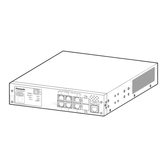
Page 12: Part Names And Functions
Part Names and Functions 10/100/1000BASE-TX ports supporting PoE power supply 10/100/1000BASE-TX ports SFP extension slot GA-ML4TWPoE++ Front panel Console port Power cord hook block Back panel Power port Ground terminal Serial Number label Power port Connect the supplied power cord to this port and connect the other end into an electric outlet. - Page 13 Status/ECO mode LED Power LED PoE LIM. LED GA-ML4TWPoE++ GIGA mode LED Temperature sensor LED Fan sensor LED DUPLEX mode LED Loop History mode LED LED Display change button POWER LED (Power) Green Light : Power is ON. : Power is OFF. ...
- Page 14 Part Names and Functions Table1. Ports and Port LED lamps 1 to 6 correspond as shown below. Port LED Display mode Behavior Description Green Light Link is established. STATUS/ECO Green Blink Transmitting and receiving data. Orange Light It is shut off via the loop detection and shutoff function/storm control or the BPDU guard.
-
Page 15: Led Display Change
2.1 LED display change ●Display style set by the LED display change button Indication on the front panel and LED lamps GA-ML4TWPoE++ LED display change button You can display the following items using the LED display switch button. Display for the connection with a connected terminal (Status mode), Display for the 1000 Mbps transmission rate (GIGA mode), Display for the full-duplex or half-duplex transmission system (DUPLEX mode), Display for ports with a loop history (Loop history mode),... - Page 16 Part Names and Functions Switch two types of Base modes and their LEDs in the following way: When Base mode is Status mode (factory default setting) Press "LED DISPLAY CHANGE BUTTON" manually. Automatic Boot Automatically returns to Base mode after 1 minute. Status mode DUPLEX Loop History...
-
Page 17: Poe Power Supply Function
The priority settings for the power supply can be set and changed from the console, etc. * For the configuration and management methods, please see the PDF version of the Operating Instructions on Panasonic’s website. Power supply while the overload is caused by a single port When the power supply which is requested exceeds 95 W via a single port and the port LED (right) blinks orange, and the power supply is stopped. -
Page 18: Installation And Configuration
Installation and Configuration 3.1 Grounding Cable Connection The chassis of the equipment must be grounded properly so that the lightning can flow to the ground, which improves the capability of the chassis for resisting the electromagnetic interference. 1. Ensure that the grounding cable is connected correctly so that the equipment is protected against lightning and interference. -
Page 19: Mounting To Rack
3.2 Mounting to rack Use the two 19-inch rack mount brackets and eight screws (for connecting the rack mount brackets and the main unit) which are included with the separately sold mount brackets, and connect the mount brackets to the four holes on the sides of the Ethernet Switch. Then, securely install the Ethernet Switch in the rack with the four screws (for the 19-inch rack mount) that come with the mount brackets, or with the screws provided on the rack. -
Page 20: Configuration Of Ip Address (Basic)
Installation and Configuration 3.3 Configuration of IP address (Basic) (1) Connect this device to your PC with the separately sold optional RJ45-DSub 9-pin console cable, then start up the terminal emulator (ZEQUO assist Plus, etc.). (2) Pressing Enter key once opens Login screen. Enter UserName and Password (the default is "manager"... - Page 21 Screen 1 Screen 2 Screen 3 Screen 4 Screen 5 * For detailed configuration and management methods, and the settings from the ZEQUO assist Plus and the Web screens, please see the PDF version of the Operating Instructions on Panasonic’s website.
-
Page 22: Troubleshooting
Troubleshooting If you find any problem, please take the following steps to check. LED The POWER LED (Power) is not lit. Check if the power cord is disconnected. Please confirm that the power cord is securely connected to the power port. ... - Page 23 (the PoE LIM. LED is not blinking orange). * For the configuration and management methods, please see the PDF version of the Operating Instructions on Panasonic’s website.