Advertisement
Quick Links
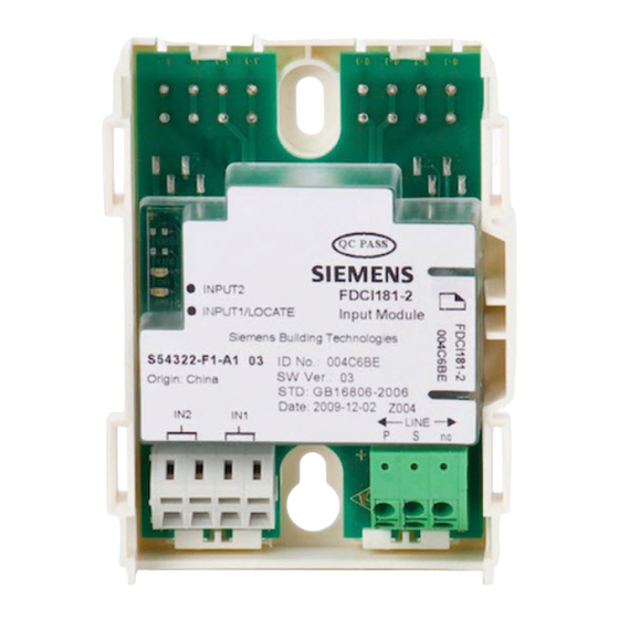
FDCIO181-2 Input/Output Module
Product Manual
Characteristic
Microprocessor-controlled signal evaluation
l
l
Automatic address setting, without encoder settings or DIP switch
l
2 monitored input, 2 monitored output
LED display of input and output status
l
Input lines monitored for open line or short circuit
l
Prevention of noise interference through intelligent analysis of input signals
l
Output lines monitored for open line or short circuit (when potential output and not activated)
l
Output monitoring configurable(on/off)
l
Control output for equipment 24 VDC, max. 2 A
l
Power supply via FD18-BUS
l
Communication with controller via FD18-BUS(detector line)
l
Directly used in dry areas. Applicable in dusty and humid areas when installed in housing
l
"Sticker Method" easy for commissioning
l
Building Technologies
Fire safety and security products
Advertisement

Related Manuals for Siemens FDCIO181-2


Summary of Contents for Siemens FDCIO181-2
- Page 1 FDCIO181-2 Input/Output Module Product Manual Characteristic Microprocessor-controlled signal evaluation Automatic address setting, without encoder settings or DIP switch 2 monitored input, 2 monitored output LED display of input and output status Input lines monitored for open line or short circuit...
- Page 2 Application Input With the input a status can be monitored, the input can be configured by controller or configuration tools as follows: “Status“ input or “Alarm“ input Lead monitoring for open line or open line and short circuit When inputting status, according to different status of contact, can be set as fallows: –...
- Page 3 Configuration The following configurations are possible through controller or configuration tool: After activating the output remains: ‒ Steady output ‒ Pulse output: How long the contact remains active can be configured by controller or configuration tools (pulse duration). Failsafe behavior when the FD18-BUS detector line is current-free or in degraded mode. The error behavior defines the position of the output in case of an error: ‒...
- Page 4 Dry contact output Potential-free contact (Output not monitored) Be used for controlling (e.g. closing a door). Output control is not monitored. An externally supplied 24 V DC voltage is not needed. The jumper on the input/output module must be plugged onto J1/J3 (Fig. 6). Fig.6 Input/output module jumper position J1 Fig.
-
Page 5: Jumper Position
Fig.8 Overview Signification LEDs for the status indication of the in-/output Jumper for the polarity of the monitoring for output 1 Connection output 1 Port for the connection of the 24V supply for output 1 Port for the connection of the 24V supply for output 2 Connection output 2 Jumper for the polarity of the monitoring for output 2 Port for the connection of the FD18-BUS detection line... -
Page 6: Installation
Installation Fig. 9 Fig. 10 Fig. 11 Fig. 12 Detection line connection Procedure with installation in the housing Preparation 1. Determine type of installation: CAUTION – Installation outside a switching cabinet or a control unit: Overheating of the in/output module! use FDCH221 housing (Fig. -
Page 7: Specification
FDCH221 S54312-F3-A1 100686595 Auxiliary Housing (IP65) 0.250 Kg Beijign Siemens Ceberus Electronics Ltd. © Data and design subject to change without notice. No. 18 Xinxi Road Shangdi Information Industry Base, Haidian District, Beijing 100085 China Tel.: +10 6296 2255 Fax: +10 6298 7387 www.sbt.siemens.com...