
Related Manuals for Siemens FDCI221


Summary of Contents for Siemens FDCI221
- Page 1 FDCI221, FDCIO221 Input module, input/output module Technical Manual Building Technologies A6V10211122_m_en_-- 2018-09-18 Control Products and Systems...
- Page 2 Issued by: Siemens Switzerland Ltd. Building Technologies Division International Headquarters Theilerstrasse 1a CH-6300 Zug Tel. +41 58 724-2424 www.siemens.com/buildingtechnologies Edition: 2018-09-18 Document ID: A6V10211122_m_en_-- © Siemens Switzerland Ltd, 2008 2 | 50 Building Technologies A6V10211122_m_en_-- Fire Safety 2018-09-18...
-
Page 3: Table Of Contents
Table of contents About this document ................5 Applicable documents ................. 7 Download center ..................8 Technical terms ..................8 History of changes ..................9 Safety ....................10 Safety instructions ..................10 Safety regulations for the method of operation ...........12 Standards and directives complied with............14 Release Notes ...................14 Structure and function ................. - Page 4 Mounting / Installation ................38 Mounting on a U-rail .................. 38 Mounting in housing FDCH221 ..............39 Connecting the module ................40 Commissioning ...................41 Maintenance / troubleshooting ..............42 Performance check ..................42 Test mode ....................42 Localization mode ..................42 Remedying faults ..................42 Specifications ..................43 Technical data ...................
-
Page 5: About This Document
Incorrect installation can take safety devices out of operation unbeknown to a layperson. Goal and purpose This document contains all the information about the input module FDCI221 and the input/output module FDCIO221. Following the instructions consistently will ensure that the product can be used safely and without any problems. - Page 6 About this document Applicable documents Target groups The information in this document is intended for the following target groups: Target group Activity Qualification Product Manager Is responsible for information Has obtained suitable specialist passing between the manufacturer training for the function and for the and regional company.
-
Page 7: Applicable Documents
List of compatibility (for 'Sinteso™' product line) A6V10212086 Input module FDCI221, input/output module FDCIO221, housing FDCH221 A6V10202196 Data sheet Input module FDCI221, Input/output module FDCIO221 A6V10229261 List of compatibility (for 'Cerberus™ PRO' product line) A6V10393192 List of compatibility (for 'Cerberus™ FIT' product line) -
Page 8: Download Center
You can download various types of documents, such as data sheets, installation instructions, and license texts via the following Internet address: https://siemens.com/bt/download Enter the document ID in the search field. You will also find information about search variants and links to mobile applications (apps) for various systems on the home page. -
Page 9: History Of Changes
About this document History of changes 1.4 History of changes The reference document's version applies to all languages into which the reference document is translated. The first edition of a language version or a country variant may, for example, be version 'd' instead of 'a' if the reference document is already this version. -
Page 10: Safety
Safety Safety instructions 2 Safety 2.1 Safety instructions The safety notices must be observed in order to protect people and property. The safety notices in this document contain the following elements: Symbol for danger Signal word Nature and origin of the danger Consequences if the danger occurs Measures or prohibitions for danger avoidance Symbol for danger... - Page 11 Safety Safety instructions How risk of injury is presented Information about the risk of injury is shown as follows: WARNING Nature and origin of the danger Consequences if the danger occurs Measures / prohibitions for danger avoidance How possible damage to property is presented Information about possible damage to property is shown as follows: NOTICE Nature and origin of the danger...
-
Page 12: Safety Regulations For The Method Of Operation
2.2 Safety regulations for the method of operation National standards, regulations and legislation Siemens products are developed and produced in compliance with the relevant European and international safety standards. Should additional national or local safety standards or legislation concerning the planning, mounting, installation,... - Page 13 Modifications to the system and to individual products may lead to faults, malfunctioning and safety risks. Written confirmation must be obtained from Siemens and the corresponding safety bodies for modifications or additions. Modules and spare parts Components and spare parts must comply with the technical specifications defined by Siemens.
-
Page 14: Standards And Directives Complied With
Personal injury or damage to property caused by poor maintenance or lack of maintenance 2.3 Standards and directives complied with A list of the standards and directives complied with is available from your Siemens contact. 2.4 Release Notes Limitations to the configuration or use of devices in a fire detection installation with a particular firmware version are possible. -
Page 15: Structure And Function
Input module FDCI221 Input/output module FDCIO221 Input module FDCI221 The FDCI221 input module has 1 input. It allows you to monitor statuses (e.g. whether a door is closed). Input/output module FDCIO221 The FDCIO221 input/output module has 1 output and 1 input. With the output, control functions can be performed. -
Page 16: Details For Ordering
S54312-F2-A1 Input/output module Scope of delivery Type Scope of delivery FDCI221 Input module FDCI221, 2x mounting foot FDCM291, 1x 3.3 k resistor, 1x 680 resistor FDCIO221 Input/output module FDCIO221, 2x mounting foot FDCM291, 2x 3.3 k resistor, 1x 680 resistor, 1x diode... -
Page 17: Product Version Es
Structure and function Product version ES 3.2 Product version ES The product version ES provides the technical status of a device in terms of software and hardware. The product version is provided as a two-digit number. You will find the details of your device's product version: On the packaging label On the product label or the type plate Product version on the packaging label... -
Page 18: Setup
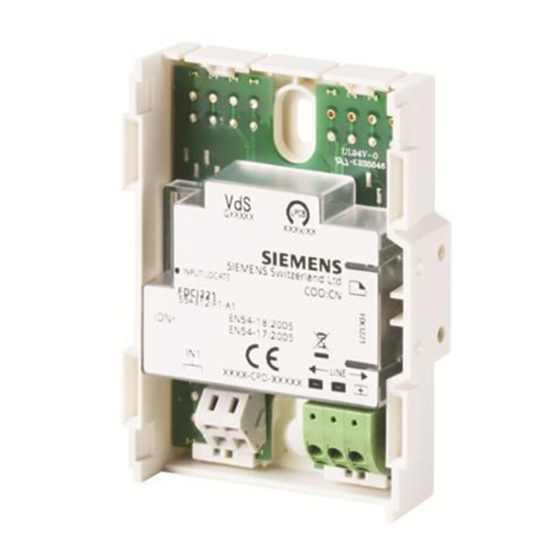
Structure and function Setup 3.3 Setup The modules consist of the module carrier, the printed circuit board and the cover cap. The printed circuit board includes the LEDs. The LEDs indicate the status of the input, output and localization mode. The cover cap of the printed circuit board is transparent such that the statuses of the LEDs are visible even when the cover cap is fitted. -
Page 19: Input/Output Module
Structure and function Setup 3.3.2 Input/output module Figure 5: Overview of input/output module 1 Connections for the detector line 4 Connections for the output 2 Connections for the input 5 Holes for mounting feet 3 Jumper for output configuration 19 | 50 A6V10211122_m_en_-- Building Technologies Fire Safety... -
Page 20: Printed Circuit Board View Of The Input Module
Structure and function Setup 3.3.3 Printed circuit board view of the input module IN 1 IN 1 LINE - LINE - LINE + Figure 6: Printed circuit board view of the input module 1 Detector line connections 3 Red LED for input status and localization mode 2 Connections for input IN1 20 | 50... -
Page 21: Printed Circuit Board View Of The Input/Output Module
Structure and function Setup 3.3.4 Printed circuit board view of the input/output module IN 1 IN 1 LINE - LINE - LINE + Figure 7: Printed circuit board view of the input/output module 1 Detector line connections 4 Jumper J1/J2 for output configuration 2 Connections for input IN1 5 Terminals for output OUT A... -
Page 22: Leds
Structure and function Setup 3.3.5 LEDs The tables below show the meaning of the LED states. Red LED for the input status and for localization mode Status LED Meaning LED off Normal operation LED flashing every 2 s Input activated LED flashing every 1 s Localization mode Red LED for the output status (for input/output module only) -
Page 23: Function
Structure and function Function 3.4 Function 3.4.1 Block diagram LINE IN 1 LOCATE OUT A µP IC-1 OC-A IN 1 OUT A Figure 8: Block diagram of input module and input/output module LINE Detector line OUT A Output (for FDCIO221 only) IN 1 Input J1, J2 Jumper plug positions (for FDCIO221 only) -
Page 24: Input
Structure and function Function The communication with the control panel is performed via the detector line. Configuration is performed on the control panel. The output must also be configured with a jumper on the input/output module. The modules are normally in operating mode. -
Page 25: Output (For Input/Output Module Only)
Structure and function Function Input module FDCI221 and input/output module FDCIO221 FDCI221 FDCIO221 3.3 k Figure 9: Connection diagram of input with monitoring for open line FDCI221 FDCIO221 3.3 k Figure 10: Connection diagram of input with monitoring for open line and short circuit 3.4.3 Output (for input/output module only) -
Page 26: Normal Operation (Output Lines Monitorable)
Structure and function Function 3.4.3.1 Normal operation (output lines monitorable) The input/output module output FDCIO221 can be used for control. In this mode the module switches the externally supplied DC 24 V voltage to the output when active. The externally supplied 24 V voltage is monitored. In the event of failure, an error message is generated. - Page 27 Structure and function Function Configuration Depending on the control panel, not all configurations may be supported. Observe the information in the 'List of compatibility' as well as in the documentation for your fire control panel. The following configurations are possible: After activation, the output remains in the following status: –...
-
Page 28: Inverted Operation (Output Lines Not Monitorable)
Structure and function Function 3.4.3.2 Inverted operation (output lines not monitorable) The output of the input/output module FDCIO221 can be used for controlling (e.g., closing a door). In this mode the module switches off the externally supplied DC 24 V voltage on the output when active. - Page 29 Structure and function Function Configuration Depending on the control panel, not all configurations may be supported. Observe the information in the 'List of compatibility' as well as in the documentation for your fire control panel. The following configurations are possible: After activation, the output remains in the following status: –...
-
Page 30: Output Not Monitored
Structure and function Function 3.4.3.3 Output not monitored This section describes the function mode when control is not monitored. An externally supplied 24 V voltage is not needed. Control functions can be performed with the output (e.g. close door). The output is designed as a potential-free relay contact. -
Page 31: Line Separator
On a loop line, all FDnet/C-NET devices remain fully functional after a single short-circuit. 3.4.5 Diagnosis levels The FDCI221 input module and the FDCIO221 input/output module largely monitor their function autonomously. The following diagnosis levels are taken from the different control measuring processes:... -
Page 32: Behavior In Degraded Mode
Structure and function Function 3.4.6 Behavior in degraded mode Applicable for the FDnet/C-NET: When the main processor of the fire control panel fails, the control panel works in degraded mode operation. Depending on the control panel type, the fire control panel can continue to perform the most important alarming and signaling functions in degraded mode operation. -
Page 33: Accessories
Structure and function Accessories 3.5 Accessories 3.5.1 Mounting foot FDCM291 For device mounting on a DIN rail TS35 Two mounting feet must always be used Compatible with: – Input module FDCI22x(-CN) – Input/output module FDCIO22x(-CN) – Output module FCA1209-Z1 – Multi line separator module FDCL221-M –... -
Page 34: M20 X 1.5 Metal Cable Gland
Structure and function Accessories 3.5.3 M20 x 1.5 metal cable gland For introducing a cable into a housing For cable diameters of 3.5…5.5 mm Temperature range: -40…+100 °C Allows for increased IP protection Compatible with: – M20 x 1.5 metal counter nut –... -
Page 35: Planning
Planning Compatibility 4 Planning When planning a project, proceed as follows: 1. Take into account the compatibility. 2. Define the place of installation. 3. Define the type of monitoring and configuration of the input. 4. Only for FDCIO221: Determine the output configuration 5. -
Page 36: Defining The Type Of Monitoring And Input Configuration
Planning Defining the type of monitoring and input configuration 4.3 Defining the type of monitoring and input configuration There must be no automatic fire detector and no manual call point connected to the inputs. Proceed as follows: 1. Define the type of input (danger input or status input). 2. -
Page 37: Defining The Output Configuration
Planning Defining the output configuration 4.4 Defining the output configuration When configuring the outputs, please proceed as follows: 1. Define the type of output: – Bistable, switched voltage, normal operation (option of monitoring output lines) – Bistable, switched voltage, inverted operation (output lines not monitored) –... -
Page 38: Mounting / Installation
Mounting / Installation Mounting on a U-rail 5 Mounting / Installation 5.1 Mounting on a U-rail NOTICE Impairment of module function due to dust or humidity The only situation in which the housing FDCH221 should not be used is if the module is installed in a closed electrical cabinet or in a control panel In case of an installation without FDCH221 housing, please proceed as follows: 1. -
Page 39: Mounting In Housing Fdch221
Mounting / Installation Mounting in housing FDCH221 5.2 Mounting in housing FDCH221 The module can be installed at any location, along with the separate FDCH221 housing. When installing the module in the housing FDCH221, proceed as follows: 1. Open the housing. 2. -
Page 40: Connecting The Module
Specialist electrical engineering knowledge is required for installation. Only an expert is permitted to carry out installation work. Incorrect installation can take safety devices out of operation unbeknown to a layperson. FDCI221 FDCI221 FDCIO221 FDCIO221 LINE –... -
Page 41: Commissioning
Commissioning 6 Commissioning The devices are commissioned via the control panel. The exact procedure is described in the control panel documentation. Conduct a performance check once commissioning is complete. 41 | 50 A6V10211122_m_en_-- Building Technologies Fire Safety 2018-09-18... -
Page 42: Maintenance / Troubleshooting
Maintenance / troubleshooting Performance check 7 Maintenance / troubleshooting 7.1 Performance check The devices are automatically subjected to a performance check during the self- test. Nevertheless, it is necessary to check the devices on site at regular intervals. Recommendation: Check the devices every year. Replace heavily soiled or damaged devices. -
Page 43: Specifications
(these devices) in the following document(s); see 'Applicable documents' chapter: Document A6V10202196 Detector line Operating voltage DC 12…33 V Operating current (quiescent): FDCI221 Max. 0.3 mA FDCIO221 Max. 0.4 mA Connection factor: FDCI221 FDCIO221 Address connection factor... - Page 44 207 x 119 x 50 mm Housing material Colors: Module carrier ~RAL 9010, pure white Housing ~RAL 9010, pure white Housing cover Transparent matt Weight [kg] FDCI221 0,060 kg FDCIO221 0,066 kg Standards European standards EN 54-17 EN 54-18 International standards IEC 60092-504...
-
Page 45: Dimensions
Specifications Dimensions 8.2 Dimensions Figure 20: Dimensions of installation variants The dimensions for FDCI221 and FDCIO221 are identical. 8.3 Environmental compatibility and disposal This equipment is manufactured using materials and procedures which comply with current environmental protection standards as best as possible. More specifically, the following measures have... -
Page 46: Annex
Annex Configuration sheet 9 Annex 9.1 Configuration sheet Mounting site Module Input module FDCI221 Input/output module FDCIO221 Mode of mounting Without housing With housing FDCH221 Input IN1 monitors ... Output OUT A controls ... Configuration for the input Parameters Value... -
Page 47: Index
Index Index Jumper Approvals ............43 Output configuration........21 Jumper position J1 CE marking ............. 43 Not monitored ..........30 Communication Jumper position J2 Detector line ........... 24 Inverted operation ........... 28 Compatibility ........... 35 Normal operation ..........26 Compatibility with control panels......35 Control panel .......... - Page 48 Index Source language ..........6 Standards ............44 Recycling ............45 Status displays Resistors LED ..............15 Input monitoring ..........24 Test mode Scope .............. 5 Service work ..........24, 42 Service work Type plate Localization mode ........24, 42 Product version ..........
- Page 49 Index 49 | 50 A6V10211122_m_en_-- Building Technologies Fire Safety 2018-09-18...
- Page 50 Issued by © Siemens Switzerland Ltd, 2008 Siemens Switzerland Ltd Technical specifications and availability subject to change without notice. Building Technologies Division International Headquarters Theilerstrasse 1a CH-6300 Zug +41 58 724 2424 www.siemens.com/buildingtechnologies Document ID: A6V10211122_m_en_-- Manual FD20 / FD720...