Table of Contents
Advertisement
Quick Links
Download this manual
See also:
Installation Manual
Advertisement
Table of Contents

Related Manuals for Huawei EM820W


Summary of Contents for Huawei EM820W
- Page 1 HUAWEI EM820W HSPA+ PC Embedded Module Hardware Guide Issue Date 2010-12-09...
- Page 2 E-mail: mobile@huawei.com Please refer color and shape to product. Huawei reserves the right to make changes or improvements to any of the products without prior notice. Copyright © Huawei Technologies Co., Ltd. 2009. All rights reserved. No part of this document may be reproduced or transmitted in any form or by any means without prior written consent of Huawei Technologies Co., Ltd.
- Page 3 HUAWEI EM820W HSPA+ PC Embedded Module Hardware Guide About This Document About This Document History Version Date Chapter Descriptions 2010-12-09 Creation Huawei Proprietary and Confidential Issue 01 (2010-12-09) Copyright © Huawei Technologies Co., Ltd.
-
Page 4: Table Of Contents
HUAWEI EM820W HSPA+ PC Embedded Module Hardware Guide Contents Contents ............................1 1 Introduction 1.1 Overview ............................1 ..........................2 2 Overall Description 2.1 About This Chapter ........................2 2.2 Function Overview ........................2 2.3 Circuit Block Diagram ........................3 2.4 Application Block Diagram ...................... - Page 5 6.2 Dimensions of the Mini PCI Express Connector ..............36 6.3 Specification Selection for Fasteners ..................37 6.3.1 Installing the EM820W on the Main Board of PC ............37 6.3.2 Romoving the EM820W from the Main Board of PC ............ 38 ...................40...
- Page 6 Table 5-5 DC power consumption (GSM/GPRS/EDGE) ............32 Table 5-6 DC power consumption(Idle and Suspend) ..............33 Table 5-7 Test conditions and results of the mechanical reliability of the EM820W module . 34 Huawei Proprietary and Confidential Issue 01 (2010-12-09)
- Page 7 Figure 6-1 Dimensions of the EM820W ..................36 Figure 6-2 Dimensions of the Mini PCI Express connector ............37 Figure 7-1 Circuits of typical interfaces in the EM820W module ..........40 Huawei Proprietary and Confidential Issue 01 (2010-12-09) Copyright © Huawei Technologies Co., Ltd.
-
Page 8: Introduction
EM820W module) is used. This document helps you to understand the interface specifications, electrical features, and related product information of the EM820W module. To facilitate its use in different fields, relevant development guides document are also provided with the module, which can be obtained through Huawei website. -
Page 9: Overall Description
HUAWEI EM820W HSPA+ PC Embedded Module Hardware Guide Overall Description Overall Description 2.1 About This Chapter This chapter gives a general description of the EM820W module and provides: Function Overview Circuit Block Diagram Application Block Diagram 2.2 Function Overview Table 2-1 Feature... -
Page 10: Circuit Block Diagram
European Conformity (CE), Federal Communications information Commission (FCC) 2.3 Circuit Block Diagram Figure 2-1 shows the circuit block diagram of the EM820W module. The application block diagram and major functional units of the EM820W module contain the following parts: Mobile data modem... -
Page 11: Application Block Diagram
HUAWEI EM820W HSPA+ PC Embedded Module Hardware Guide Overall Description Figure 2-1 Circuit block diagram of the EM820W module 2.4 Application Block Diagram Figure 2-2 Application block diagram of the EM820W module Huawei Proprietary and Confidential Issue 01 (2010-12-09) Copyright © Huawei Technologies Co., Ltd. -
Page 12: Description Of The Application Interfaces
WAKE_NB_N Signal NC Pins 3.2 Mini PCI Express Interface The EM820W has a standard Mini PCI Express interface, which consists of several major signals, as shown in the following table. Table 3-1 Pin definitions of the Mini PCI-E Interface Definition of the EM820W Mini PCI Express pins... - Page 13 HUAWEI EM820W HSPA+ PC Embedded Module Hardware Guide Description of the Application Interfaces Definition of the EM820W Mini PCI Express pins Mini PCI HUAWEI Pin Additional Direction to Express Description Description Module Standard Description 3.3Vaux VCC_3V3 3.3 V DC supply rails Input from the PC side.
- Page 14 HUAWEI EM820W HSPA+ PC Embedded Module Hardware Guide Description of the Application Interfaces Definition of the EM820W Mini PCI Express pins Mini PCI HUAWEI Pin Additional Direction to Express Description Description Module Standard Description PERp0 Not connected. Mini Card ground.
-
Page 15: Power Sources And Grounds
The PCI Express Mini Card provides two power sources: one is 3.3 Vaux (+3.3 Vaux) and the other is 1.5 V (+ 1.5 V). For the EM820W, however, +3.3 Vaux is the only voltage supply that is available. The input voltage is 3.3 V±9%, as specified by PCI Express Mini CEM Specifications 1.2 . -
Page 16: Usb Signals
3.45 3.5 USB Signals The EM820W is compliant with USB 2.0 specification. It supports full-speed (12 Mbit/s) and high-speed (480 Mbit/s) modes when acting as a peripheral and supports low-speed, full-speed, and high-speed modes when acting as a host. The USB 2.0 specifications allow peripherals to support any one or more of these speeds. -
Page 17: Usim Signals
SIM card may get destroyed. 3.6.1 USIM Interface Schematic Reference There is no SIM card interface circuit in the EM820W module, and users need to add the USIM interface circuit. Figure 3-2 shows the definition of interface signals and the typical USIM interface schematic. -
Page 18: Design Guide
HUAWEI EM820W HSPA+ PC Embedded Module Hardware Guide Description of the Application Interfaces Figure 3-2 USIM interface schematic on PC Figure 3-3 Pin definition of the SIM card Socket pin1: SIM_VCC pin4: pin2: SIM_RESET pin5: NULL pin3: SIM_CLK pin6: SIM_DATA 3.6.2 Design Guide... -
Page 19: Table 3-6 Sim Rst Requirements
HUAWEI EM820W HSPA+ PC Embedded Module Hardware Guide Description of the Application Interfaces module board before entering the EM820W processor. There is also an EMI filtering and ESD protection circuit between the SIM card interface and the Mini PCI interface on the user’s board. -
Page 20: Certification Test
HUAWEI EM820W HSPA+ PC Embedded Module Hardware Guide Description of the Application Interfaces Table 3-8 SIM IO requirements Minimum Maximum 0.7Vcc –0.3 0.2 Vcc 0.7 Vcc Vcc+0.3 The V max of 0.45 V for the output is specified at an output current of 3 mA whereas the max of 0.4 V for the SIM IO input is specified at an input current of 1 mA. -
Page 21: W_Disable# Signal
Nearly all PC companies comply with this specification. 3.8 LED_WWAN# Signal The LED_WWAN signal of the EM820W can allow the voltage of 3.3 V and absorb the current from 5 mA to 40 mA. According to the given circuit, in order to reduce the current of the LED, a resistance of 1 kΩ... -
Page 22: Figure 3-4 Led_Wwan# Signal Reference Circuit Diagram
Figure 3-4 LED_WWAN# signal reference circuit diagram Normally, when the HUAWEI module is enabled, the LED is on, and when disabled, the LED is off. The wink mode of the LED can be customized according to the requirement of the client. -
Page 23: Wake_Nb_N Signal
PC . This signal is used for 3G module to wake up the host. It’s designed as a OC gate, so it should be pulled up by the host and it’s active-low. 3.10 NC Pins The NC pins are not internally connected in the EM820W. Huawei Proprietary and Confidential Issue 01 (2010-12-09) -
Page 24: Rf Specifications
HUAWEI EM820W HSPA+ PC Embedded Module Hardware Guide RF Specifications RF Specifications 4.1 Operating Frequencies Table 4-1 shows the RF bands supported by EM820W. Table 4-1 RF bands Operating Band UMTS 2100 (Band Ⅰ ) 1920–1980 MHz 2110–2170 MHz 1850–1910 MHz 1930–1990 MHz... -
Page 25: Test Standards
The instrument compensation needs to be set according to the actual cable conditions. 4.2.2 Test Standards Huawei modules meet all 3GPP test standards relating to both 2G and 3G. Each module has passed stringent tests in the factory, thus the quality of the modules is guaranteed. -
Page 26: Conducted Transmit Power
In addition, the transmission cable from the antenna port of the EM820W to the antenna is also part of the antenna. The cable loss increases with the cable length and the frequency. It is recommended that the cable loss should be as low as possible, for example, U.FL-... -
Page 27: Table 4-4 Isolation Between The Master Antenna And The Wi-Fi Antenna
Antenna type Antenna direction The master antenna must be placed as near as possible to the EM820W to minimize the cable length. The slave antenna needs to be installed perpendicularly to the master antenna. The slave antenna can be placed farther away from the EM820W. - Page 28 HUAWEI EM820W HSPA+ PC Embedded Module Hardware Guide RF Specifications Frequency Transmit Conducted Wi-Fi Front End Band Frequency Transmit Isolator Filter Attenuation Power (dBm) (dB) (dB) GSM850 824–849 MHz GSM900 880–915 MHz 1710–1785 MHz 1850–1910 MHz S11 or VSWR S11 (return loss) indicates the degree to which the input impedance of an antenna matches the reference impedance (50 ohm).
- Page 29 Take the RF transmission cable inside the laptop into account when measuring any of the preceding antenna indicators. Huawei cooperates with various antenna suppliers who are able to make suggestions on antenna design, for example, Amphenol, Skycross, Pulse etc.
-
Page 30: Interference
To lessen the effects of interference sources on the module, you can use an LCD with optimized performance, shield the LCD interference signals, shield the signal cable of the board, or design filter circuits. Huawei is capable of making technical suggestions on radio performance improvement of the module. 4.4.3 GSM/WCDMA Antenna Requirements... -
Page 31: Radio Test Environment
The antenna efficiency, antenna gain, radiation pattern, total radiated power (TRP), and TIS can be tested in a microwave testing chamber. Huawei has a complete set of OTA test environment (SATIMO microwave testing chambers and ETS microwave testing chambers). The testing chambers are certified by professional organizations and are applicable to testing at frequencies ranging from 380 MHz to 6 GHz. -
Page 32: Design Recommendations
HUAWEI EM820W HSPA+ PC Embedded Module Hardware Guide RF Specifications Figure 4-1 SATIMO microwave testing chamber 4.5 Design Recommendations Recommendations for Designing the Module Antennas The design recommendations are as follows: It is recommended that the module antennas are designed at the upper edge, left edge, or right edge of the laptop screen. -
Page 33: Esd Protection For The Antenna Interface
4.6 ESD Protection for the Antenna Interface In practical application, pay attention to the ESD protection for the antenna interface of the EM820W module. Incorrect operation may result in permanent damage to the RF components. Figure 4-3 shows the ESD protection circuit recommended for the antenna interface. -
Page 34: Figure 4-3 Esd Protection Circuit Recommended For The Antenna Interface
HUAWEI EM820W HSPA+ PC Embedded Module Hardware Guide RF Specifications Figure 4-3 ESD protection circuit recommended for the antenna interface It is recommended that you pay attention to the junction capacitance of the TVS diode when you choose the model of the TVS diode. Ensure that the junction capacitance of the TVS diode is lower than 1 pF. -
Page 35: Electrical And Reliability Features
Reliability Features EMC and ESD Features 5.2 Extreme Working Conditions Table 5-1 lists the extreme working conditions for the EM820W module. Using the EM820W module beyond these conditions may result in permanent damage to the module. 5.3 Working and Storage Temperatures and Humidity Table 5-1 lists the working and storage temperatures and humidity for the EM820W module. -
Page 36: Electrical Criteria Of Application Interfaces
°C storage Moisture [1]: When the EM820W module works at this temperature, all its RF indexes comply with the 3GPP TS 45.005 specifications. [2]: When the EM820W module works at this temperature, certain RF indexes do not comply with the 3GPP TS 45.005 specifications. -
Page 37: Power Supply Features
5.5 Power Supply Features 5.5.1 Power Supply The EM820W receives its power supply from a 3.3 V power source, which must satisfy all requirements of PCI Express Mini CEM specifications, such as voltage tolerance and peak and normal current. The detailed requirements are listed in Table 5-3. - Page 38 HUAWEI EM820W HSPA+ PC Embedded Module Hardware Guide Electrical and Reliability Features Description Band Test Value Units Power (dBm) (850M) 10 dBm Tx Power 24 dBm Tx Power Band Ⅷ 1 dBm Tx Power (900M) 10 dBm Tx Power 24 dBm Tx Power...
-
Page 39: Table 5-5 Dc Power Consumption (Gsm/Gprs/Edge)
HUAWEI EM820W HSPA+ PC Embedded Module Hardware Guide Electrical and Reliability Features Table 5-5 DC power consumption (GSM/GPRS/EDGE) Description Test Value Units Configuration GPRS850 1 Up/1 Down 2 Up/1 Down 1 Up/1 Down 2 Up/1 Down GPRS900 1 Up/1 Down... -
Page 40: Reliability Features
HUAWEI EM820W HSPA+ PC Embedded Module Hardware Guide Electrical and Reliability Features Description Test Value Units Configuration 4 Up/1 Down 1 Up/1 Down 2 Up/1 Down 4 Up/1 Down EDGE1900 1 Up/1 Down 2 Up/1 Down 4 Up/1 Down 1 Up/1 Down... -
Page 41: Table 5-7 Test Conditions And Results Of The Mechanical Reliability Of The Em820W Module
HUAWEI EM820W HSPA+ PC Embedded Module Hardware Guide Electrical and Reliability Features Table 5-7 Test conditions and results of the mechanical reliability of the EM820W module Item Test Condition Standard Low-temperature Temperature: –40±2ºC IEC60068 storage Test duration: 24 h High-temperature Temperature: 85±2ºC... -
Page 42: Emc And Esd Features
Ground plane: HUAWEI Wireless recommends a common ground plane for analog/digital/RF grounds. A metallic case or plastic casing with conductive paint is recommended, except for areas around the antenna. The HUAWEI EM820W Embedded Module does not include any protection against high voltage. Huawei Proprietary and Confidential Issue 01 (2010-12-09) -
Page 43: Mechanical Specifications
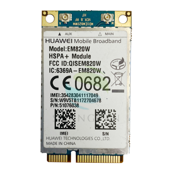
6.1 Dimensions and Interfaces 6.1.1 Dimensions and Interfaces of EM820W The dimensions of EM820W are 50.95 mm (length) × 30 mm (width) × 4.5 mm (height). Figure 6-1 shows the dimensions of EM820W in detail. Figure 6-1 shows the appearance of the interfaces on the EM820W. -
Page 44: Specification Selection For Fasteners
6.3.1 Installing the EM820W on the Main Board of PC To install the EM820W on the main board of the PC, do the following: Step 1 Insert the Mini PCI Express connector of the EM820W into the WWAN Mini PCI Express interface on the main board of PC. -
Page 45: Romoving The Em820W From The Main Board Of Pc
Mechanical Specifications Step 2 Press downwards to fix the EM820W in the module slot. Step 3 Use a screwdriver to fix the EM820W on the main board of the PC with two screws provided in the EM820W packing box. Step 4 Insert the connector of the main antenna into the MAIN antenna interface (M) of the EM820W according to the indication on the label of the EM820W. - Page 46 HUAWEI EM820W HSPA+ PC Embedded Module Hardware Guide Mechanical Specifications Step 2 Remove the two screws with the screwdriver. Step 3 Slide backwards the two clips to release the EM820W from the slot. Then, lift up the EM820W. Huawei Proprietary and Confidential Issue 01 (2010-12-09)
-
Page 47: Appendix A Circuits Of Typical Interfaces
HUAWEI EM820W HSPA+ PC Embedded Module Hardware Guide Appendix A Circuits of Typical Interfaces Appendix A Circuits of Typical Interfaces Figure 7-1 Circuits of typical interfaces in the EM820W module Huawei Proprietary and Confidential Issue 01 (2010-12-09) Copyright © Huawei Technologies Co., Ltd. -
Page 48: Appendix B Acronyms And Abbreviations
HUAWEI EM820W HSPA+ PC Embedded Module Appendix B Acronyms and Hardware Guide Abbreviations Appendix B Acronyms and Abbreviations Acronym or Abbreviation Expansion Baseband European Conformity Coding Scheme Circuit Switched Data direct current data circuit-terminating equipment direct memory access data terminal equipment... -
Page 49: Huawei Em820W Hspa+ Pc Embedded Module Hardware Guide
HUAWEI EM820W HSPA+ PC Embedded Module Appendix B Acronyms and Hardware Guide Abbreviations Acronym or Abbreviation Expansion negative temperature coefficient PBCCH Packet Broadcast Control Channel printed circuit board protocol data unit Power manage Unit radio frequency RoHS Restriction of the use of certain Hazardous...