Huawei BBU3900 Hardware Description
Hide thumbs
Also See for BBU3900:
- Hardware maintenance manual (58 pages) ,
- Installation manual (58 pages) ,
- Description (29 pages)

Related Manuals for Huawei BBU3900


Summary of Contents for Huawei BBU3900
- Page 1 BBU3900 V200 Hardware Description Issue Date 2010-11-10 HUAWEI TECHNOLOGIES CO., LTD.
- Page 3 All other trademarks and trade names mentioned in this document are the property of their respective holders. Notice The purchased products, services and features are stipulated by the contract made between Huawei and the customer. All or part of the products, services and features described in this document may not be within the purchase scope or the usage scope.
-
Page 5: About This Document
About This Document About This Document Introduction This document describes the BBU3900 hardware, such as boards, module, ports, cables, and connectors, and the functions of the hardware. Product Version The following table lists the product versions related to this document. - Page 6 NodeB and the RNC. 4 BBU3900 Cables This describes the BBU3900 cables. The cables are the PGND cable, power cable,E1 cable, E1 surge protection transfer cable, FE cable, FE surge protection transfer cable, Iub optical cable, monitoring signal cable between the APMI and the BBU, CPRI optical cable, alarm cable, EMUA signal cable, monitoring signal cable between the CMUA and the BBU, and GPS clock signal cable.
- Page 7 Multi-level menus are in boldface and separated by the ">" signs. For example, choose File > Create > Folder. Keyboard Operations The keyboard operations that may be found in this document are defined as follows. Issue 11 (2010-11-10) Huawei Proprietary and Confidential Copyright © Huawei Technologies Co., Ltd.
- Page 8 Press the primary mouse button twice continuously and quickly without moving the pointer. Drag Press and hold the primary mouse button and move the pointer to a certain position. Huawei Proprietary and Confidential Issue 11 (2010-11-10) Copyright © Huawei Technologies Co., Ltd.
-
Page 9: Table Of Contents
BBU3900 Hardware Description Contents Contents About This Document........................iii 1 Changes in the BBU3900 Hardware Description..............1-1 2 DBS3900 Monitoring System....................2-1 2.1 Customized Alarm Input..........................2-2 2.2 BBU Monitoring Port............................2-4 2.3 Monitoring Principles of the Cabinets......................2-5 3 BBU3900 Equipment........................3-1 3.1 Exterior of the BBU3900..........................3-2 3.2 BBU3900 Components...........................3-2... - Page 10 Contents Hardware Description 4.15 Monitoring Signal Cable Between the CMUA and the BBU..............4-21 4.16 BBU Alarm Cable............................4-22 4.17 GPS Clock Signal Cable..........................4-24 5 Auxiliary Devices of the BBU3900..................5-1 5.1 EMUA................................5-3 5.2 10 U Indoor Centralized Rack.........................5-3 5.3 OMB................................5-4 5.4 IMB03................................5-6 5.5 DCDU-03................................5-9...
- Page 11 Figure 3-1 BBU3900............................3-2 Figure 3-2 The position of the ESN........................3-2 Figure 3-3 Slots of the BBU3900.........................3-3 Figure 3-4 BBU3900 in typical configuration..................... 3-5 Figure 3-5 Panel of the WMPT..........................3-6 Figure 3-6 LEDs besides the three ports on the WMPT..................3-7 Figure 3-7 DIP switches on the WMPT.......................3-9...
- Page 12 Figure 5-10 Exterior of the WGRU........................5-15 Figure 5-11 WGRU installed in the WGRU box....................5-16 Figure 5-12 Front panel of the WGRU......................5-16 Figure 5-13 Rear panel of the WGRU box......................5-17 Huawei Proprietary and Confidential Issue 11 (2010-11-10) Copyright © Huawei Technologies Co., Ltd.
- Page 13 Figure 5-18 Panel of the UFLP..........................5-22 Figure 5-19 Panel of the USLP2........................5-23 Figure 5-20 Mapping relationship between the pins in the input and output ports on the USLP2....5-23 Issue 11 (2010-11-10) Huawei Proprietary and Confidential Copyright © Huawei Technologies Co., Ltd.
- Page 15 Table 2-2 Relationship between the IN0 to IN3 ports on the USLP2 and the number of customized alarms ....................................2-3 Table 2-3 Ports on the UPEU and UEIU......................2-5 Table 3-1 Board configuration of the BBU3900....................3-4 Table 3-2 LEDs on the WMPT..........................3-6 Table 3-3 LEDs beside the three ports.........................3-7 Table 3-4 Ports on the WMPT..........................3-8...
- Page 16 Table 5-17 Ports on the panel of the UFLP......................5-22 Table 5-18 Ports on the panel of the USLP2......................5-23 Table 5-19 Mapping relationship between the pins in the input and output ports on the USLP2......5-24 Huawei Proprietary and Confidential Issue 11 (2010-11-10) Copyright © Huawei Technologies Co., Ltd.
-
Page 17: Changes In The Bbu3900 Hardware Description
Hardware Description 1 Changes in the BBU3900 Hardware Description Changes in the BBU3900 Hardware Description This describes the changes in the BBU3900 Hardware Description 11 (2010-11-10) This is the tenth commercial release. Compared with issue 10 (2010-09-10), no information is added. - Page 18 BBU3900 1 Changes in the BBU3900 Hardware Description Hardware Description 09 (2010-06-05) This is the eighth commercial release. Compared with issue 08 (2010-03-25), this issue includes the following new topics: 2 DBS3900 Monitoring System Compared with issue 08 (2010-03-25), no information is changed.
- Page 19 BBU3900 Hardware Description 1 Changes in the BBU3900 Hardware Description Part Modification 3.2.3 WBBP WBBPd board is added. Compared with issue 05 (2009-11-15), this issue deletes the following topics: DBS3900 hardware configuration 05 (2009-11-15) This is the fourth commercial release.
- Page 20 BBU3900 1 Changes in the BBU3900 Hardware Description Hardware Description Part Modification 3.2.7 UTRP The name of UTRP5 is modified to UTRP6. Compared with issue 01 (2009-10-30), no information is deleted. 01 (2008-12-30) This is the draft version. Huawei Proprietary and Confidential Issue 11 (2010-11-10) Copyright ©...
-
Page 21: Dbs3900 Monitoring System
MON port on the BBU through the RS485 serial bus. In this manner, the boards monitor the cabinet. Issue 11 (2010-11-10) Huawei Proprietary and Confidential Copyright © Huawei Technologies Co., Ltd. -
Page 22: Customized Alarm Input
If using this method, connect the device to be monitored to the SLPU for surge protection, and then connect the device to the EXT_ALM port on the BBU, as shown in Figure 2-1. Huawei Proprietary and Confidential Issue 11 (2010-11-10) Copyright © Huawei Technologies Co., Ltd. -
Page 23: Figure 2-1 Customized Alarms Collected By The Upeu Or Ueiu
The EMUA can be configured for the DBS3900 that requires more than 16 Boolean alarm signals. Each EMUA supports 32 Boolean alarm inputs and two RS485 signal inputs. Issue 11 (2010-11-10) Huawei Proprietary and Confidential Copyright © Huawei Technologies Co., Ltd. -
Page 24: Bbu Monitoring Port
The BBU houses the UPEU and UEIU for monitoring. Each board has two Boolean input ports and two RS485 input ports, and each Boolean input port receives four Boolean inputs. Figure shows the slot assignment for the UPEU and UEIU. Huawei Proprietary and Confidential Issue 11 (2010-11-10) Copyright © Huawei Technologies Co., Ltd. -
Page 25: Monitoring Principles Of The Cabinets
MON port on the BBU through the RS485 serial bus. In this manner, the boards monitor the cabinet. Issue 11 (2010-11-10) Huawei Proprietary and Confidential Copyright © Huawei Technologies Co., Ltd. -
Page 26: Figure 2-5 Monitoring Principles Of The Dbs3900 When The Bbu Is Installed In The Apm30
For details about the functions of monitoring ports on the HPMI, see HPMI. For details about the functions of monitoring ports on the PMU, see PMU. The PMU is configured only in the APM30H (Ver.A). Huawei Proprietary and Confidential Issue 11 (2010-11-10) Copyright © Huawei Technologies Co., Ltd. -
Page 27: Figure 2-6 Monitoring Principles Of The Dbs3900 When The Bbu Is Installed In The Apm30H (Ver.a)
For details about the functions of monitoring ports on the HPMI, see HPMI. For details about the functions of monitoring ports on the PMU, see PMU. The PMU is configured only in the APM30H (Ver.B). Issue 11 (2010-11-10) Huawei Proprietary and Confidential Copyright © Huawei Technologies Co., Ltd. -
Page 28: Figure 2-8 Monitoring Principles Of The Dbs3900 When The Bbu Is Installed In The Apm30H (Ver.b)
Figure 2-10 Monitoring principles of the DBS3900 when the BBU is installed in the OMB COM_IN / COM1 MON0 / MON1 Cable to be connected on site Cable connected before delivery Monitoring from HEUA source to destination Huawei Proprietary and Confidential Issue 11 (2010-11-10) Copyright © Huawei Technologies Co., Ltd. -
Page 29: Figure 2-11 Monitoring Principles Of The Dbs3900 In The Bbu+Rru+Icr (110V/220V) Scenario
OMB. The devices monitored by the HEUA is not shown in the figures. For details, see the description about the boards. For details about the functions of monitoring ports on the HEUA, see HEUA. Issue 11 (2010-11-10) Huawei Proprietary and Confidential Copyright © Huawei Technologies Co., Ltd. -
Page 30: Figure 2-14 Monitoring Principles Of The Dbs3900 When The Bbu Is Installed In The Omb
For details about the monitoring of the EMUA, see 2.1 Customized Alarm Input. For details about the connections of all monitoring signal cables in the cabinet, see Monitoring Signal Cable Connections. 2-10 Huawei Proprietary and Confidential Issue 11 (2010-11-10) Copyright © Huawei Technologies Co., Ltd. -
Page 31: Bbu3900 Equipment
The BBU3900, which has a case structure, is 19 inches wide and 2 U high. 3.2 BBU3900 Components This section describes the boards and module of the BBU3900 in terms of their functions, ports, LEDs, and DIP switches. Issue 11 (2010-11-10) Huawei Proprietary and Confidential Copyright ©... -
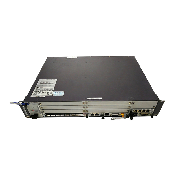
Page 32: Exterior Of The Bbu3900
3.1 Exterior of the BBU3900 The BBU3900, which has a case structure, is 19 inches wide and 2 U high. The dimensions (W x D x H) of the BBU3900 are 442 mm x 310 mm x 86 mm. Figure 3-1 shows the BBU3900. -
Page 33: Board Configuration Of The Bbu3900
The WCDMA Baseband Process Unit (WBBP) of the BBU3900 processes baseband signals. 3.2.4 FAN The FAN unit of the BBU3900 controls the fan speed, monitors the temperature of the FAN unit, and dissipates the heat in the BBU. 3.2.5 UPEU The Universal Power and Environment Interface Unit (UPEU) is a mandatory board of the BBU3900. -
Page 34: Table 3-1 Board Configuration Of The Bbu3900
BBU3900 3 BBU3900 Equipment Hardware Description Table 3-1 Board configuration of the BBU3900 Board Mandatory/ Maximum Installation Requirements Optional Configured Slot Number WMPT Mandatory slot 6 or 7 The WMPT is preferentially configured in Slot 7. WBBP Mandatory slots 0 to 3... -
Page 35: Wmpt
The UELP and UFLP need to be optionally configured in the BBU or SLPU on site according to the field requirements. Figure 3-4 shows the BBU3900 in typical configuration with one WMPT, one WBBP, one UPEU, and one FAN. Figure 3-4 BBU3900 in typical configuration 3.2.2 WMPT... -
Page 36: Figure 3-5 Panel Of The Wmpt
Providing the reference clock Processing signaling and managing resources for other boards in the BBU3900 Providing USB ports, one of which facilitates automatic BBU3900 upgrading when a USB disk is inserted during software installation and data configuration Providing four E1s/T1s which support ATM and IP protocols... -
Page 37: Figure 3-6 Leds Besides The Three Ports On The Wmpt
No data transmission is ongoing. LEDs beside the FE0 Green (LINK) The connections are electrical port functional. The connections are faulty. Yellow (ACK) Blinking Data transmission is ongoing. Issue 11 (2010-11-10) Huawei Proprietary and Confidential Copyright © Huawei Technologies Co., Ltd. -
Page 38: Table 3-4 Ports On The Wmpt
The WMPT has two DIP switches: SW1 for setting the E1/T1 working mode and SW2 for setting the protection grounding for the E1/T1 cables receiving 4-way signals. Figure 3-7 shows the DIP switches on the WMPT. Huawei Proprietary and Confidential Issue 11 (2010-11-10) Copyright © Huawei Technologies Co., Ltd. -
Page 39: Figure 3-7 Dip Switches On The Wmpt
The E1 impedance is set to 75 ohms. Other settings of the DIP bits Disabled Table 3-6 Settings of SW1 DIP Status Description Switch Balanced Mode Issue 11 (2010-11-10) Huawei Proprietary and Confidential Copyright © Huawei Technologies Co., Ltd. -
Page 40: Wbbp
DIP bits of SW2 to ON so that the faults are rectified. 3.2.3 WBBP The WCDMA Baseband Process Unit (WBBP) of the BBU3900 processes baseband signals. Panels The WBBP has three types of panels, as shown in... -
Page 41: Table 3-7 Specifications Of The Wbbp
Blinking (on for 0.125 second Software is being loaded to the and off for 0.125 second) board. Green The board is running properly. The WBBP is not in use. Issue 11 (2010-11-10) Huawei Proprietary and Confidential 3-11 Copyright © Huawei Technologies Co., Ltd. -
Page 42: Table 3-9 Leds Indicating The Status Of The Sfp Links
Label Connector Type Description CPRIx SFP female Data transmission port between the BBU and the RF module, supporting input and output of optical and electrical signals 3-12 Huawei Proprietary and Confidential Issue 11 (2010-11-10) Copyright © Huawei Technologies Co., Ltd. -
Page 43: Fan
The six CPRI ports are available on the WBBPd configured only in slot 2 or 3, and the CPRI ports are not available on the WBBPd configured in other port. 3.2.4 FAN The FAN unit of the BBU3900 controls the fan speed, monitors the temperature of the FAN unit, and dissipates the heat in the BBU. Panel Figure 3-11 shows the panel of the FAN unit. -
Page 44: Upeu
3.2.5 UPEU The Universal Power and Environment Interface Unit (UPEU) is a mandatory board of the BBU3900. It converts -48 V or +24 V DC power to +12 V DC power. Panels The UPEU is classified into the Universal Power and Environment Interface Unit Type A (UPEUA) and the Universal Power and Environment Interface Unit Type B (UPEUB). -
Page 45: Figure 3-13 Panel Of The Upeub
The UPEU provides two RS485 ports and two ports for eight Boolean signals. When configured in different slots, the ports on the UPEU have different functions. Figure 3-14 shows the slots in the BBU. Figure 3-14 Slots in the BBU Issue 11 (2010-11-10) Huawei Proprietary and Confidential 3-15 Copyright © Huawei Technologies Co., Ltd. -
Page 46: Ueiu
The Universal Environment Interface Unit (UEIU) transmits monitoring and alarm signals from the external devices to the main control and transmission unit. Panel Figure 3-15 shows the panel of the UEIU. Figure 3-15 Panel of the UEIU 3-16 Huawei Proprietary and Confidential Issue 11 (2010-11-10) Copyright © Huawei Technologies Co., Ltd. -
Page 47: Utrp
No.1 RS485 signal input port 3.2.7 UTRP The Universal Transmission Processing unit (UTRP) is the transmission extension board of the BBU3900. It provides eight E1s/T1s, one unchannelized STM-1/OC-3 port, and four electrical ports or two optical ports. Specification Table 3-16 describes the specifications of the UTRP. -
Page 48: Figure 3-16 Panel Of The Utrp2 Supporting Two Optical Ports
UTRP9 supporting four electrical ports. Figure 3-19 Panel of the UTRP supporting four electrical ports Functions The UTRP has the following functions: 3-18 Huawei Proprietary and Confidential Issue 11 (2010-11-10) Copyright © Huawei Technologies Co., Ltd. -
Page 49: Table 3-17 Leds On The Panel Of The Utrp
ON for 2s and OFF The board is for 2s reporting a minor alarm. ON for 1s and OFF The board is for 1s reporting a major alarm. Issue 11 (2010-11-10) Huawei Proprietary and Confidential 3-19 Copyright © Huawei Technologies Co., Ltd. -
Page 50: Table 3-18 Leds On The Ethernet Ports Of The Utrp2 And Utrp9
Port Type Quantity Connector Type FE/GE0 to FE/GE1 FE/GE optical port SFP connector Table 3-20 describes the ports on the UTRP3 and UTRP4 supporting eight E1s/T1s. 3-20 Huawei Proprietary and Confidential Issue 11 (2010-11-10) Copyright © Huawei Technologies Co., Ltd. -
Page 51: Figure 3-20 Dip Switch On The Utrp3 Or Utrp4
Figure 3-20 DIP switch on the UTRP3 or UTRP4 Table 3-23, Table 3-24, and Table 3-25 describe how to set the DIP switches on the UTRP. Issue 11 (2010-11-10) Huawei Proprietary and Confidential 3-21 Copyright © Huawei Technologies Co., Ltd. -
Page 52: Table 3-23 Dip Switch Sw1 On The Utrp
No.7 and SW2 corresponds to E1s No.0 to No.3. Table 3-25 DIP switch SW3 on the UTRP DIP Status Description Switch T1 Mode The E1 impedance is set to 120 ohms. 3-22 Huawei Proprietary and Confidential Issue 11 (2010-11-10) Copyright © Huawei Technologies Co., Ltd. -
Page 53: Uscu
The USCU has the following functions: The USCU provides interface for an external RGPS device (such as a reused device of the operator), Metro1000 device, BITS device, and TOD input. Issue 11 (2010-11-10) Huawei Proprietary and Confidential 3-23 Copyright © Huawei Technologies Co., Ltd. -
Page 54: Table 3-26 Leds On The Uscu
USCU and the main control board is enabled. The serial port for communication between the USCU and the main control board is disabled. 3-24 Huawei Proprietary and Confidential Issue 11 (2010-11-10) Copyright © Huawei Technologies Co., Ltd. -
Page 55: Table 3-27 Leds On The Tod Port
Receives BITS clock signals, and supports adaptive connector input of 2.048 MHz and 10 MHz clock reference source M-1PPS port SMA coaxial Receives 1PPS signals from the M1000 connector Issue 11 (2010-11-10) Huawei Proprietary and Confidential 3-25 Copyright © Huawei Technologies Co., Ltd. -
Page 57: Bbu3900 Cables
BBU3900 Cables About This Chapter This describes the BBU3900 cables. The cables are the PGND cable, power cable,E1 cable, E1 surge protection transfer cable, FE cable, FE surge protection transfer cable, Iub optical cable, monitoring signal cable between the APMI and the BBU, CPRI optical cable, alarm cable, EMUA signal cable, monitoring signal cable between the CMUA and the BBU, and GPS clock signal cable. - Page 58 The FE/GE surge protection transfer cable is an optional cable that connects the main control board to the UFLP. 4.9 FE/GE Optical Cable The FE/GE optical cable is used to transmit optical signals between the BBU3900 and the transmission device. This cable is optional. 4.10 CPRI Optical Cable The CPRI optical cable transmits CPRI signals between the BBU and the RRU or between RRUs.
-
Page 59: List Of Bbu3900 Cables
4 BBU3900 Cables 4.1 List of BBU3900 Cables This describes the BBU3900 cables. The cables are the PGND cable, BBU power cable, E1/T1 cable, E1/T1 surge protection transfer cable, FE/GE cable, FE/GE surge protection transfer cable, Iub optical cable, CPRI optical cable, APMI-BBU monitoring signal cable, BBU alarm cable, EMUA monitoring signal cable, Monitoring signal cable for the HEUA and GPS clock signal cable. - Page 60 Signal Cable EXT_ALM Between the CMUA and the BBU 4.16 BBU RJ-45 connector BBU/UPEU or RJ-45 connector Port on the Alarm Cable UEIU/ external EXT_ALM monitoring device Huawei Proprietary and Confidential Issue 11 (2010-11-10) Copyright © Huawei Technologies Co., Ltd.
-
Page 61: Pgnd Cable
Figure 4-2 shows the BBU power cable with OT terminals at the bare wire end as an example. Issue 11 (2010-11-10) Huawei Proprietary and Confidential Copyright © Huawei Technologies Co., Ltd. -
Page 62: Figure 4-2 Bbu Power Cable (1)
Table 4-2 Pin assignment for the wires of the -48 V power cable Pin on the 3V3 Color Description Connector Blue -48 V Black Huawei Proprietary and Confidential Issue 11 (2010-11-10) Copyright © Huawei Technologies Co., Ltd. -
Page 63: Bbu Power Cable(Omb)
Figure 4-4 Appearance of power cable(AC OMB) (1) 3V3 power connector for the BBU (2) H4 connector (3) 3V3 power connector for the HEUA Figure 4-5 shows the appearance of power cable(DC OMB). Issue 11 (2010-11-10) Huawei Proprietary and Confidential Copyright © Huawei Technologies Co., Ltd. -
Page 64: E1/T1 Cable
Table 4-4 Connectors of the 75-ohm E1 coaxial cable Cable One End The other End 75-ohm E1 coaxial cable DB26 male connector L9 male connector L9 female connector SMB female connector Huawei Proprietary and Confidential Issue 11 (2010-11-10) Copyright © Huawei Technologies Co., Ltd. -
Page 65: Table 4-5 Pin Assignment For The Wires Of The 75-Ohm E1 Coaxial Cable
Ring RX3- X1.7 RX4+ X1.8 Ring RX4- X1.19 TX1+ X1.20 Ring TX1- X1.21 TX2+ X1.22 Ring TX2- X1.23 TX3+ X1.24 Ring TX3- X1.25 TX4+ X1.26 Ring TX4- Issue 11 (2010-11-10) Huawei Proprietary and Confidential Copyright © Huawei Technologies Co., Ltd. -
Page 66: E1/T1 Surge Protection Transfer Cable
The E1/T1 surge protection transfer cable has a DB26 male connector at one end and a DB25 male connector at the other end, as shown in Figure 4-7. 4-10 Huawei Proprietary and Confidential Issue 11 (2010-11-10) Copyright © Huawei Technologies Co., Ltd. -
Page 67: Figure 4-7 E1/T1 Surge Protection Transfer Cable
Twisted pair cable X2.10 X1.23 X2.11 X1.8 Twisted pair cable X2.12 X1.7 X2.13 X1.1 Twisted pair cable X2.14 X1.2 X2.15 X1.25 Twisted pair cable X2.24 X1.26 X2.25 Issue 11 (2010-11-10) Huawei Proprietary and Confidential 4-11 Copyright © Huawei Technologies Co., Ltd. -
Page 68: Fe/Ge Cable
Twisted pair X2.6 X1.3 White and X2.3 green X1.4 Blue Twisted pair X2.4 X1.5 White and blue X2.5 X1.8 Brown Twisted pair X2.8 X1.7 White and X2.7 brown 4-12 Huawei Proprietary and Confidential Issue 11 (2010-11-10) Copyright © Huawei Technologies Co., Ltd. -
Page 69: Fe/Ge Surge Protection Transfer Cable
Twisted pair X2.8 X1.7 White X2.7 4.9 FE/GE Optical Cable The FE/GE optical cable is used to transmit optical signals between the BBU3900 and the transmission device. This cable is optional. Issue 11 (2010-11-10) Huawei Proprietary and Confidential 4-13 Copyright © Huawei Technologies Co., Ltd. -
Page 70: Cpri Optical Cable
When connecting the BBU3900 and the transmission device using the FE/GE optical cable, adhere to the following rules: The TX port on the BBU3900 is connected to the RX port on the transmission device. The RX port on the BBU3900 is connected to the TX port on the transmission device. -
Page 71: Figure 4-13 Multi-Mode Optical Cable
0.03 m long. A single-mode optical cable has a DLC connector at one end and two FC connectors at the other end, as shown in Figure 4-15. Issue 11 (2010-11-10) Huawei Proprietary and Confidential 4-15 Copyright © Huawei Technologies Co., Ltd. -
Page 72: Figure 4-15 Single-Mode Optical Cable
Pin Assignment Table 4-10, Table 4-11, and Table 4-12 describe the labels and recommended connections for the branch cables of the CRPI optical cable. 4-16 Huawei Proprietary and Confidential Issue 11 (2010-11-10) Copyright © Huawei Technologies Co., Ltd. -
Page 73: Monitoring Signal Cable Between The Apmi And The Bbu
4.11 Monitoring Signal Cable Between the APMI and the This describes the monitoring signal cable between the APMI and the BBU. It transmits the environment monitoring signals of the power cabinet to the BBU. Issue 11 (2010-11-10) Huawei Proprietary and Confidential 4-17 Copyright © Huawei Technologies Co., Ltd. -
Page 74: Monitoring Signal Cable For The Transmission Cabinet
One end of the monitoring signal cable is an RJ-45 connector and the other end consists of three pairs of wires in different colors, as shown in Figure 4-18. 4-18 Huawei Proprietary and Confidential Issue 11 (2010-11-10) Copyright © Huawei Technologies Co., Ltd. -
Page 75: Monitoring Signal Cable Between The Heua And The Bbu
The monitoring signal cable between the HEUA and the BBU transmits the monitoring information collected by the HEUA to the BBU. Appearance Figure 4-19 shows the monitoring signal cable between the HEUA and the BBU. Issue 11 (2010-11-10) Huawei Proprietary and Confidential 4-19 Copyright © Huawei Technologies Co., Ltd. -
Page 76: Emua Monitoring Signal Cable
This section describes the EMUA monitoring signal cable. It transmits monitoring signals from the EMUA to the BBU. This cable is delivered with the EMUA. Exterior Figure 4-20 shows the EMUA monitoring signal cable. 4-20 Huawei Proprietary and Confidential Issue 11 (2010-11-10) Copyright © Huawei Technologies Co., Ltd. -
Page 77: Monitoring Signal Cable Between The Cmua And The Bbu
CMUA to the BBU. Exterior Figure 4-21 shows the monitoring signal cable between the CMUA and the BBU. Issue 11 (2010-11-10) Huawei Proprietary and Confidential 4-21 Copyright © Huawei Technologies Co., Ltd. -
Page 78: Bbu Alarm Cable
The BBU alarm cable has an RJ-45 connector at each end, as shown in Figure 4-22. However, an RJ-45 connector at one end may be removed, and an appropriate terminal may be added according to the field requirements. 4-22 Huawei Proprietary and Confidential Issue 11 (2010-11-10) Copyright © Huawei Technologies Co., Ltd. -
Page 79: Figure 4-22 Bbu Alarm Cable
Boolean value input 7- (GND) EXT- X1.1 White and Twisted X2.1 Boolean value input 0+ ALM0 orange pair X1.2 Orange X2.2 Boolean value input 0- (GND) Issue 11 (2010-11-10) Huawei Proprietary and Confidential 4-23 Copyright © Huawei Technologies Co., Ltd. -
Page 80: Gps Clock Signal Cable
The GPS clock signal cable has an SMA male connector at one end and an N-type female connector at the other end, as shown in Figure 4-23. Figure 4-23 GPS clock signal cable (1) SMA male connector (2) N-type female connector 4-24 Huawei Proprietary and Confidential Issue 11 (2010-11-10) Copyright © Huawei Technologies Co., Ltd. -
Page 81: Auxiliary Devices Of The Bbu3900
5 Auxiliary Devices of the BBU3900 Auxiliary Devices of the BBU3900 About This Chapter This describes the auxiliary devices of the BBU3900. The devices consist of the SLPU, OMB Cabinet and WGRU. 5.1 EMUA The Environment Monitoring Unit (EMUA) monitors the internal environment of the cabinet and reports related alarms. - Page 82 BBU3900 5 Auxiliary Devices of the BBU3900 Hardware Description clock source. These timing signals and positioning information can be used to generate PPS signals and Network Assisted GPS (AGPS) positioning information. The WGRU is optional for the NodeB which is installed in the WGRU box. The NodeB can be configured with one WGRU which provides the positioning function.
-
Page 83: Emua
BBU3900 Hardware Description 5 Auxiliary Devices of the BBU3900 5.1 EMUA The Environment Monitoring Unit (EMUA) monitors the internal environment of the cabinet and reports related alarms. The EMUA is connected to the main equipment through alarm cables, monitoring the environment information of the equipment room and cabinet. -
Page 84: Omb
BBU3900 5 Auxiliary Devices of the BBU3900 Hardware Description Provides a 10 U space for a distributed base station. Supports power input of -48 V DC. Connects the main ground cable for the rack and ground cable for equipment to the ground terminal on the rack. -
Page 85: Figure 5-2 Omb Cabinet
BBU3900 Hardware Description 5 Auxiliary Devices of the BBU3900 Figure 5-2 OMB cabinet Table 5-2 shows the dimensions of the OMB cabinet. Table 5-2 Dimensions of the OMB cabinet Length (mm) Width (mm) Height (mm) Functions The functions of the OMB cabinet are as follows: Providing 3 U installation space for the distributed BTS. -
Page 86: Imb03
BBU3900 5 Auxiliary Devices of the BBU3900 Hardware Description 5.4 IMB03 The Indoor Mini Box (IMB03) is an indoor subrack with a small capacity. It houses a built-in BBU, AC/DC power equipment, DCDU, or other power equipment. Exterior Figure 5-3 shows an IMB03. -
Page 87: Figure 5-4 Dc Imb03
BBU3900 Hardware Description 5 Auxiliary Devices of the BBU3900 Figure 5-4 DC IMB03 (1) DCDU-03B (2) BBU An AC IMB03 houses a BBU and AC/DC power equipment, as shown in Figure 5-5. Issue 11 (2010-11-10) Huawei Proprietary and Confidential Copyright © Huawei Technologies Co., Ltd. -
Page 88: Figure 5-5 Ac Imb03
BBU3900 5 Auxiliary Devices of the BBU3900 Hardware Description Figure 5-5 AC IMB03 (1) AC/DC power equipment (2) BBU Specifications Table 5-3 lists the specifications of the IMB03. Table 5-3 Specifications of the IMB03 Item Specification Dimensions 560 mm (22.05 in.) x 425 mm (16.73 in.) x 180 mm (7.09 in.) (height x width x depth) -
Page 89: Dcdu-03
BBU3900 Hardware Description 5 Auxiliary Devices of the BBU3900 5.5 DCDU-03 The Direct Current Distribution Unit-03 (DCDU-03) supplies DC power to each component in the cabinet. The height of the DCDU-03 is 1 U. It can be classified into the DCDU-03B and DCDU-03C according to the configured MCBs and application scenarios. -
Page 90: Figure 5-7 Ports On The Panel Of The Dcdu-03
BBU3900 5 Auxiliary Devices of the BBU3900 Hardware Description DCDU DC Output Power Applicatio Model Terminal Consumpti Specificati Quantity n Scenario Equipment DCDU-03C LOAD0 to Transmissio 12 A Separated LOAD5 n equipment macro base of the station in the customer... -
Page 91: Ac/Dc Power Equipment
BBU3900 Hardware Description 5 Auxiliary Devices of the BBU3900 Table 5-5 Ports on the panel of the DCDU-03 Port Specification Cross-Sectional Area Remarks (Unit: mm DC input Supports the l DCDU-03B: 25 When the DCDU-03 is used terminal M6 2-hole OT... -
Page 92: Table 5-6 Panel Of The Ac/Dc Power Equipment
BBU3900 5 Auxiliary Devices of the BBU3900 Hardware Description (5) Power distribution control switch for the transmission (6) Rectifier equipment (7) Monitoring port (8) DC output port LOAD1 (9) DC output port LOAD2 (10) Output port for the batteries BATT... -
Page 93: Table 5-8 Leds On The Panel Of The Monitoring Module
BBU3900 Hardware Description 5 Auxiliary Devices of the BBU3900 Label Color Name Status Description An error occurs during the running of the rectifier. ALARM Yellow Alarm LED Output overcurrent alarm or overtemperature alarm Blinking The communication is disrupted. The rectifier is running properly. -
Page 94: Figure 5-9 Dip Switches On The Pmu
BBU3900 5 Auxiliary Devices of the BBU3900 Hardware Description Figure 5-9 DIP switches on the PMU Table 5-9 describes the settings of the DIP switches on the PMU. Table 5-9 Settings of the DIP switches on the PMU Function Operation... -
Page 95: Wgru
BBU3900 Hardware Description 5 Auxiliary Devices of the BBU3900 Function Operation Selects baud rate for Set as ON, indicating that the communicating with the BTS baud rate is 9600. (If it is set as OFF, the baud rate is 19200.) -
Page 96: Figure 5-11 Wgru Installed In The Wgru Box
BBU3900 5 Auxiliary Devices of the BBU3900 Hardware Description Figure 5-11 WGRU installed in the WGRU box Panel The components on the front panel of the WGRU suite are LEDs, RST button, and output ports. Figure 5-12 shows the front panel of the WGRU. -
Page 97: Figure 5-13 Rear Panel Of The Wgru Box
BBU3900 Hardware Description 5 Auxiliary Devices of the BBU3900 Figure 5-13 Rear panel of the WGRU box Indicators on the Front Panel of the WGRU This describes indicators on the front panel of the WGRU. There are three indicators, that is the RUN, ALM, and ACT indicators on the front panel of the WGRU. -
Page 98: Slpu
BBU3900 5 Auxiliary Devices of the BBU3900 Hardware Description Ports on the Front Panel of the WGRU The following describes the ports on the front panel of the WGRU. The ports consist of PPS1, PPS2, COM1, COM2, CLK1, and CLK2. -
Page 99: Exterior Of Slpu
BBU3900 Hardware Description 5 Auxiliary Devices of the BBU3900 5.8.3 UELP Each Universal E1/T1 Lightning Protection Unit (UELP) provides surge protection for four paths of E1/T1 signals. 5.8.4 UFLP The universal FE/GE lightning protection (UFLP) board is a universal FE surge protection unit, each UFLP supports 2-way FE surge protection. -
Page 100: Uelp
BBU3900 5 Auxiliary Devices of the BBU3900 Hardware Description Table 5-13 Configuration principles of the SLPU (1) Board Optional/ Maximum Slot Configuration Mandatory Quantity Restriction UELP Optional Slots 0 to 3 The priorities of the slots in configuration are as follows in... -
Page 101: Figure 5-17 Dip Switch On The Uelp
BBU3900 Hardware Description 5 Auxiliary Devices of the BBU3900 Ports Table 5-15 lists the ports of the UELP. Table 5-15 Ports of the UELP Label Connector Description INSIDE DB25 connector Connected to the board for transmission in the base station... -
Page 102: Uflp
BBU3900 5 Auxiliary Devices of the BBU3900 Hardware Description Table 5-16 DIP switch on the UELP Bit Status Description Switch Not grounded Other status Grounded NOTE The 75-ohm E1 cable can be either grounded or not grounded, whereas the 120-ohm E1 cable and the 100- ohm T1 cable cannot be grounded. -
Page 103: Uslp2
BBU3900 Hardware Description 5 Auxiliary Devices of the BBU3900 5.8.5 USLP2 The Universal Signal Lightning Protection Unit Type 2 (USLP2) is a dry contact surge protection unit. It is optional and can be installed in the SLPU. Panel Figure 5-19 shows the panel of the USLP2. -
Page 104: Table 5-19 Mapping Relationship Between The Pins In The Input And Output Ports On The Uslp2
BBU3900 5 Auxiliary Devices of the BBU3900 Hardware Description Table 5-19 Mapping relationship between the pins in the input and output ports on the USLP2 Input Output Label Label IN0.1 OUT1 OUT1.1 IN0.2 OUT1.2 IN0.3 OUT1.4 IN0.4 OUT1.5 IN1.1 OUT1.3 IN1.2...