Table of Contents
Advertisement
Advertisement
Table of Contents

Related Manuals for ABB RTAC-01


Summary of Contents for ABB RTAC-01
- Page 1 ABB Drives User’s Manual Pulse Encoder Interface Module RTAC-01...
- Page 3 Pulse Encoder Interface Module RTAC-01 User’s Manual 3AFE 64486853 REV A EN EFFECTIVE: 1.5.2002 © 2002 ABB Oy. All Rights Reserved.
-
Page 5: Safety Instructions
There can be dangerous voltages inside the drive from external control circuits even when the drive mains power is shut off. Exercise appropriate care when working on the unit. Neglecting these instructions can cause physical injury or death. RTAC-01 User’s manual... - Page 6 Safety instructions RTAC-01 User’s manual...
-
Page 7: Table Of Contents
The RTAC-01 module ........ - Page 8 I/O Module Adapter installation ....... 4-1 Appendix A – Technical data RTAC-01 User’s manual...
-
Page 9: Chapter 1 - Introduction
Intended The manual is intended for the people who are audience responsible for commissioning and using an RTAC-01 Pulse Encoder Interface module with the ACS 800 drive. The reader is expected to have a basic knowledge of electrical fundamentals, electrical wiring practices and how to operate the drive. -
Page 10: What This Manual Contains
Chapter 1 – Introduction What this manual This manual contains information on the wiring, contains configuration and use of the RTAC-01 module. Safety instructions are featured in the first few pages of this manual. Chapter 2 – Overview contains a short description of the RTAC-01 Pulse Encoder Interface module, a delivery checklist and warranty information. -
Page 11: Chapter 2 - Overview
This chapter contains a short description of the Pulse Encoder Interface module, a delivery checklist, and warranty information. The RTAC-01 The RTAC-01 Pulse Encoder Interface module offers an module interface for a digital pulse encoder connection. A pulse encoder should be used if accurate speed or position (angle) feedback from the motor shaft is required. -
Page 12: Delivery Check
• Encoder supply voltage selection jumper • Two screws (M3×8 mm) • This manual. Compatibility The RTAC-01 is compatible with ACS 800 Standard Application Program version ASXR7000 or later. Warranty and The warranty for your ABB drive and options covers liability manufacturing defects. -
Page 13: Chapter 3 - Installation
ACS 800 Hardware Manual. Mounting The RTAC-01 is to be inserted into the position marked SLOT 1 or SLOT 2 on the drive. The module is held in place with plastic retaining clips and two screws. The... -
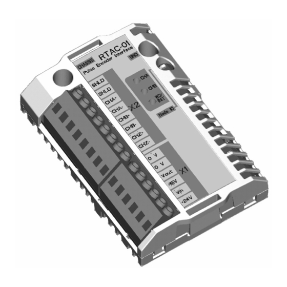
Page 14: Terminal Designations
• Input channels isolated from the logic, power supply, and earth • When the drive runs in the Forward direction, channel A should lead channel B by 90° (electrical) • Channel Z: One pulse per revolution (used in positioning applications only) RTAC-01 User’s manual... -
Page 15: Power Consumption
Chapter 3 – Installation Power Without an external power supply, the RTAC-01 can consumption supply 5 W (at either 15 V or 24 V DC) to the encoder. For higher power, an external power supply is required. As the power consumption of the module depends on many factors (e.g. - Page 16 Figure 3-2 Approximate power consumption of an encoder for four different cable lengths. The chart is based on a measurement with a 24 V DC, 1024 ppr pulse encoder with differential outputs coupled to a motor shaft rotating at 1500 rpm. RTAC-01 User’s manual...
-
Page 17: Encoder Wiring
However, if the encoder is isolated from the motor and earth, the cable shields are to be connected to the encoder housing also. Note: Do not route the encoder cables parallel to power (eg. motor) cables. RTAC-01 User’s manual... -
Page 18: Phasing
Forward should be connected to RTAC input A, the output channel that trails to RTAC input B. The zero reference output channel (usually marked 0, N or Z) needs to be connected in positioning applications only. RTAC-01 User’s manual... -
Page 19: Encoder Output Types
The diagram presents some typical encoder output types types. The following pages include wiring diagrams for each output type. Open collector Open emitter Push-pull (Sinking) (Sourcing) = Encoder input power supply voltage = Load resistor at encoder output channel RTAC-01 User’s manual... -
Page 20: Wiring Diagrams
1 and 2 should be wired to RTAC terminals B- and A- respectively.) Differential connection RTAC SHLD SHLD V OUT +15V Encoder supply V IN voltage selection +24V (15 or 24 V) Figure 3-3 Differential wiring of pulse encoders with push-pull outputs RTAC-01 User’s manual... - Page 21 1 and 2 should be wired to RTAC terminals B- and A- respectively.) Single-ended connection RTAC SHLD SHLD V OUT +15V Encoder supply V IN voltage selection +24V (15 or 24 V) Figure 3-4 Single-ended wiring of pulse encoders with push-pull outputs RTAC-01 User’s manual...
- Page 22 RTAC SHLD SHLD 24V: 1.8…2.2 kΩ 15V: 1.0…1.5 kΩ 0.5 W V OUT +15V Encoder supply V IN voltage selection +24V (15 or 24 V) Figure 3-5 Wiring of pulse encoders with open collector (sinking) outputs. 3-10 RTAC-01 User’s manual...
- Page 23 RTAC SHLD SHLD 24V: 1.8…2.2 kΩ 15V: 1.0…1.5 kΩ 0.5 W V OUT +15V Encoder supply V IN voltage selection +24V (15 or 24 V) Figure 3-6 Wiring of pulse encoders with open emitter (sourcing) outputs. RTAC-01 User’s manual 3-11...
-
Page 24: Node Address Selection
Chapter 3 – Installation Node address If the RTAC-01 module is mounted onto external I/O selection Module Adapter AIMA-01, choose the proper node ID for the module using the node ID selector (S1). The settings 0…F correspond to node IDs 16…31. The default setting is 0 (node ID 16). -
Page 25: Diagnostic Leds
Chapter 4 – Fault tracing Diagnostic LEDs There are three diagnostic LEDs on the RTAC-01 module. The CHA (green) and CHB (green) LEDs show the activity on channels A and B. The WD/INIT (yellow) LED shows the status of the module. - Page 26 Chapter 4 – Fault tracing RTAC-01 User’s manual...
- Page 27 Hardware Manual are in effect. Hardware settings: • Rotary switch for node ID selection (range 16…31) Connectors: • 38-pin parallel bus connector • Two (one 6-pole, one 8-pole) non-detachable screw- type terminal blocks for max. 2.5 mm wire. RTAC-01 User’s manual...
- Page 28 1.5 kV AC, 1 minute General • Max. power consumption: 140 mA (5 V) + 55 mA (24 V) • Estimated min. lifetime: 100 000 h • All materials UL/CSA-approved • Complies with EMC standards EN 50081-2 and EN 50082-2 RTAC-01 User’s manual...
- Page 30 ABB Oy ABB Inc. AC Drives Drives & Power Products P.O. Box 184 16250 West Glendale Drive FIN-00381 Helsinki New Berlin, WI 53151 FINLAND Telephone:+358 10 222 000 Telephone:262 785-8378 Fax: +358 10 222 2681 800 243-4384 Internet: www.abb.com Fax:...