ABB Relion 650 Series Commissioning Manual
Bay control
Hide thumbs
Also See for Relion 650 Series:
- Technical manual (754 pages) ,
- Applications manual (382 pages) ,
- Commissioning manual (182 pages)
Table of Contents
Advertisement
Quick Links
Advertisement
Table of Contents

Related Manuals for ABB Relion 650 Series


Summary of Contents for ABB Relion 650 Series
- Page 1 ® Relion 650 SERIES Bay control REC650 Version 1.1 ANSI Commissioning manual...
- Page 3 Document ID: 1MRK 511 248-UUS Issued: November 2019 Revision: A Product version: 1.1 © Copyright 2011 ABB. All rights reserved...
- Page 4 Copyright This document and parts thereof must not be reproduced or copied without written permission from ABB, and the contents thereof must not be imparted to a third party, nor used for any unauthorized purpose. The software or hardware described in this document is furnished under a license and may be used or disclosed only in accordance with the terms of such license.
- Page 5 Directive 2004/108/EC) and concerning electrical equipment for use within specified voltage limits (Low-voltage directive 2006/95/EC). This conformity is the result of tests conducted by ABB in accordance with the product standards EN 50263 and EN 60255-26 for the EMC directive, and with the product standards EN 60255-1 and EN 60255-27 for the low voltage directive.
- Page 6 In case any errors are detected, the reader is kindly requested to notify the manufacturer. Other than under explicit contractual commitments, in no event shall ABB be responsible or liable for any loss or damage resulting from the use of this manual or the application of the equipment.
-
Page 7: Table Of Contents
Checking VT circuits......................... 30 Checking the RTXP test switch ...................... 31 4.10 Checking binary input and output circuits...................31 4.10.1 Binary input circuits........................32 4.10.2 Binary output circuits........................32 4.11 Checking optical connections......................32 Bay control REC650 Commissioning manual © Copyright 2011 ABB. All rights reserved... - Page 8 Checking the phase current operate value, Pickup_N set below 7.3.7.2 Checking the residual (ground fault) current operate value Pickup_PH ........................... 50 7.3.7.3 Checking the re-trip and back-up times................51 Bay control REC650 Commissioning manual © Copyright 2011 ABB. All rights reserved...
- Page 9 Overfrequency protection SAPTOF (81)..................63 7.5.2.1 Verifying the settings....................... 63 7.5.2.2 Completing the test......................... 64 7.5.3 Rate-of-change frequency protection SAPFRC (81)..............64 7.5.3.1 Verifying the settings.......................64 7.5.3.2 Completing the test........................65 Bay control REC650 Commissioning manual © Copyright 2011 ABB. All rights reserved...
- Page 10 Commissioning and maintenance of the fault clearing system..........81 8.1.1 Installation and commissioning....................81 8.1.2 Commissioning tests........................82 8.1.3 Periodic maintenance tests......................82 8.1.3.1 Visual inspection........................83 8.1.3.2 Maintenance tests........................83 Bay control REC650 Commissioning manual © Copyright 2011 ABB. All rights reserved...
- Page 11 Warnings............................89 9.2.3 Additional indications........................90 Correction procedures........................90 9.3.1 Changing and setting the password..................90 9.3.2 Identifying IED application problems..................90 9.3.2.1 Inspecting the wiring....................... 90 Section 10 Glossary......................95 Bay control REC650 Commissioning manual © Copyright 2011 ABB. All rights reserved...
-
Page 13: Introduction
The commissioning personnel must have a basic knowledge of handling electronic equipment. The commissioning and maintenance personnel must be well experienced in using protection equipment, test equipment, protection functions and the configured functional logics in the IED. Bay control REC650 Commissioning manual © Copyright 2011 ABB. All rights reserved... -
Page 14: Product Documentation
IED should be commissioned. The operation manual contains instructions on how to operate the IED once it has been commissioned. The manual provides instructions for monitoring, controlling and setting the IED. Bay control REC650 Commissioning manual © Copyright 2011 ABB. All rights reserved... -
Page 15: Document Revision History
Communication protocol manual, IEC 61850 1MRK 511 242-UUS Communication protocol manual, IEC 60870-5-103 1MRK 511 243-UUS Point list manual, DNP3 1MRK 511 244-UUS Table continues on next page Bay control REC650 Commissioning manual © Copyright 2011 ABB. All rights reserved... -
Page 16: Symbols And Conventions
Abbreviations and acronyms in this manual are spelled out in the glossary. The glossary also contains definitions of important terms. • Push button navigation in the LHMI menu structure is presented by using the push button icons, for example: Bay control REC650 Commissioning manual © Copyright 2011 ABB. All rights reserved... - Page 17 • Dimensions are provided both in inches and mm. If it is not specifically mentioned then the dimension is in mm. Bay control REC650 Commissioning manual © Copyright 2011 ABB. All rights reserved...
-
Page 19: Safety Information
Do not touch circuitry during operation. Potentially lethal voltages and currents are present. M2364-2 v1 Always use suitable isolated test pins when measuring signals in open circuitry. Potentially lethal voltages and currents are present. Bay control REC650 Commissioning manual © Copyright 2011 ABB. All rights reserved... -
Page 20: Caution Signs
M2695-2 v2 Always transport PCBs (modules) using certified conductive bags. M2696-2 v1 Do not connect live wires to the IED. Internal circuitry may be damaged Bay control REC650 Commissioning manual © Copyright 2011 ABB. All rights reserved... -
Page 21: Note Signs
Note signs IP1497-1 v1.1.1 M19-2 v3.1.1 Observe the maximum allowed continuous current for the different current transformer inputs of the IED. See technical data. Bay control REC650 Commissioning manual © Copyright 2011 ABB. All rights reserved... -
Page 23: Available Functions
OV2PTOV Two step overvoltage protection ROV2PTOV Two step residual overvoltage protection LOVPTUV Loss of voltage check Frequency protection SAPTUF Underfrequency function SAPTOF Overfrequency function SAPFRC Rate-of-change frequency protection Bay control REC650 Commissioning manual © Copyright 2011 ABB. All rights reserved... -
Page 24: Control And Monitoring Functions
SPC8GGIO Single point generic control 8 signals AUTOBITS AutomationBits, command function for DNP3.0 I103CMD Function commands for IEC60870-5-103 I103IEDCMD IED commands for IEC60870-5-103 Table continues on next page Bay control REC650 Commissioning manual © Copyright 2011 ABB. All rights reserved... - Page 25 Configurable logic Q/T, used for invalidate data INDCOMBSPQT Configurable logic Q/T, single point indication logic signal combinator combining value with quality and time Table continues on next page Bay control REC650 Commissioning manual © Copyright 2011 ABB. All rights reserved...
- Page 26 Function status fault protection for IEC60870-5-103 I103IED IED status for IEC60870-5-103 I103SUPERV Supervison status for IEC60870-5-103 I103USRDEF Status for user defined signals for IEC60870-5-103 Table continues on next page Bay control REC650 Commissioning manual © Copyright 2011 ABB. All rights reserved...
-
Page 27: Designed To Communicate
Basic functions included in all products INTERRSIG Self supervision with internal event list SELFSUPEVLST Self supervision with internal event list SNTP Time synchronization TIMESYNCHGEN Time synchronization Table continues on next page Bay control REC650 Commissioning manual © Copyright 2011 ABB. All rights reserved... - Page 28 FTP access with password DOSFRNT Denial of service, frame rate control for front port DOSLAN1 Denial of service, frame rate control for LAN1 DOSSCKT Denial of service, socket flow control Bay control REC650 Commissioning manual © Copyright 2011 ABB. All rights reserved...
-
Page 29: Starting Up
• Administration rights on the PC to set up IP addresses • Product documentation (engineering manual, installation manual, commissioning manual, operation manual, technical manual and communication protocol manual) Bay control REC650 Commissioning manual © Copyright 2011 ABB. All rights reserved... -
Page 30: Checking The Power Supply
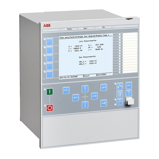
M11727-3 v6 The following sequence is expected when the IED is energized. • The green Ready LEDpicks up instantly flashing and the ABB logo is shown on the LCD. • After approximately 30 seconds, "Starting" is shown on the LCD. -
Page 31: Setting Up Communication Between Pcm600 And The Ied
A special cable is needed to connect two physical Ethernet interfaces together without a hub, router, bridge or switch in between. The Tx and Rx signal wires must be crossed in the cable to Bay control REC650 Commissioning manual © Copyright 2011 ABB. All rights reserved... - Page 32 DHCPServer, the IEDs DHCP server for the front port assigns an IP address for the computer. The computer must be configured to obtain its IP address automatically as described in the following procedure. Select Network Connections in the PC. Bay control REC650 Commissioning manual © Copyright 2011 ABB. All rights reserved...
- Page 33 IEC09000356 V1 EN-US Figure 4: Right-click Local Area Connection and select Properties Select the TCP/IP protocol from the list of configured components using this connection and click Properties. Bay control REC650 Commissioning manual © Copyright 2011 ABB. All rights reserved...
- Page 34 IP address is not set to be obtained automatically by the IED, see used and if the Figure 7. The IP address must be different from the IP address chosen for the IED. Bay control REC650 Commissioning manual © Copyright 2011 ABB. All rights reserved...
-
Page 35: Writing An Application Configuration To The Ied
IED restart, when necessary. Be sure to set the correct technical key in the IED and PCM600 to prevent writing an application configuration to a wrong IED. Bay control REC650 Commissioning manual © Copyright 2011 ABB. All rights reserved... -
Page 36: Checking Ct Circuits
Correct possible errors before continuing to test the circuitry. Test the circuitry. • Polarity check • VT circuit voltage measurement (primary injection test) • Grounding check • Phase relationship • Insulation resistance check Bay control REC650 Commissioning manual © Copyright 2011 ABB. All rights reserved... -
Page 37: Checking The Rtxp Test Switch
(such as a measurement probe) may violate the female connector and prevent a proper electrical contact between the printed circuit board and the external wiring connected to the screw terminal block. Bay control REC650 Commissioning manual © Copyright 2011 ABB. All rights reserved... -
Page 38: Binary Input Circuits
An IED equipped with optical connections requires a minimum depth of 180 mm (7.2 inches) for plastic fiber cables and 275 mm (10.9 inches) for glass fiber cables. Check the allowed minimum bending radius from the optical cable manufacturer. Bay control REC650 Commissioning manual © Copyright 2011 ABB. All rights reserved... -
Page 39: Establishing Connection And Verifying The Iec 61850 Station Communication
The best way to verify the communication up to the application layer is to use a protocol analyzer, for example, an Ethereal that is connected to the substation bus, and monitor the communication." Bay control REC650 Commissioning manual © Copyright 2011 ABB. All rights reserved... -
Page 41: Testing Ied Operation
In certain cases, only modes with a high probability of coming into operation need to be checked when commissioned to verify the configuration and settings. Bay control REC650 Commissioning manual © Copyright 2011 ABB. All rights reserved... -
Page 42: Activating Test Mode
TestMode to Enabled . Save the changes. As a consequence, the yellow pickupLED starts flashing as a reminder and remains flashing until the test mode is switched off. Bay control REC650 Commissioning manual © Copyright 2011 ABB. All rights reserved... -
Page 43: Preparing The Connection To The Test Equipment
The IED can be equipped with a test switch of type RTXP8, RTXP18 or RTXP24 or FT. The test switch and its associated test plug handles are a part of the COMBITEST or FT system of ABB, which provides secure and convenient testing of the IED. -
Page 44: Releasing The Function To Be Tested
All functions that were blocked or released in a previous Test mode is set to Enabled , are reset test mode session, that is, the parameter when a new test mode session is started. Procedure Bay control REC650 Commissioning manual © Copyright 2011 ABB. All rights reserved... -
Page 45: Verifying Analog Primary And Secondary Measurement
; I1 and I2 amplitude, range and angle CVMMXN S; P; Q; PF; Ilag; Ilead; U; I and f amplitude, range and angle Table continues on next page Bay control REC650 Commissioning manual © Copyright 2011 ABB. All rights reserved... -
Page 46: Testing Protection Functionality
Use the disturbance handling tool in PCM600 to evaluate that the protection function has received the correct data and responded correctly (signaling and timing). • Use the event viewer tool in PCM600 to check that only expected events have occurred. Bay control REC650 Commissioning manual © Copyright 2011 ABB. All rights reserved... -
Page 47: Testing Functionality
Tests/Function status/Current/PHPIOC(50,I>>)/1:PHPIOC. The Signal Monitoring in PCM600 shows the same signals that are available on the local HMI. To verify the settings the following fault type should be tested: Bay control REC650 Commissioning manual © Copyright 2011 ABB. All rights reserved... -
Page 48: Measuring The Operate Limit Of Set Values
55° if forward directional function is selected. 1 out of 3 currents for operation is chosen: The voltage angle of phase A is the reference. The voltage angle of phase A is the reference. Bay control REC650 Commissioning manual © Copyright 2011 ABB. All rights reserved... -
Page 49: Completing The Test
Ensure that the maximum continuous current, supplied from the current source used for the test of the IED, does not exceed four times the rated current value of the IED. Bay control REC650 Commissioning manual © Copyright 2011 ABB. All rights reserved... -
Page 50: Measuring The Operate Limit Of Set Values
Check that all trip and trip contacts operate according to the configuration (signal matrixes) Reverse the direction of the injected current and check that the step does not operate. Bay control REC650 Commissioning manual © Copyright 2011 ABB. All rights reserved... -
Page 51: Four Step Non-Directional Residual Overcurrent Protection
10. INcosPhiPU Measure the operate time of the timer by injecting a current two times the set VNRelPU . value and the polarizing voltage 1.2 · Bay control REC650 Commissioning manual © Copyright 2011 ABB. All rights reserved... - Page 52 Continue to test another function or complete the test by setting the test mode to Operate area RCA = 0° en06000650_ansi.vsd ANSI06000650 V1 EN-US Figure 9: Characteristic with ROADir restriction Bay control REC650 Commissioning manual © Copyright 2011 ABB. All rights reserved...
- Page 53 The expected value depends on whether definite or inverse time was selected. Disabled . Continue to test another function or complete the test by setting the test mode to Bay control REC650 Commissioning manual © Copyright 2011 ABB. All rights reserved...
- Page 54 Continue to test another function or complete the test by setting the test mode to RCA = 0° ROA = 80° Operate area en06000652_ansi.vsd ANSI06000652 V1 EN-US Figure 11: Example characteristic Non-directional ground fault current protection SEMOD175060-117 v5 Procedure Bay control REC650 Commissioning manual © Copyright 2011 ABB. All rights reserved...
-
Page 55: Completing The Test
LPTTR(26,T>)/1:LPTTR for the function, or for each individual function in a chain, to be tested Blocked to Yes , for each individual function that has been next. Remember to set the parameter tested. Bay control REC650 Commissioning manual © Copyright 2011 ABB. All rights reserved... -
Page 56: Breaker Failure Protection Ccrbrf (50Bf)
IN>Pickup_N . Repeat the fault condition and increase the current in steps until trip appears. Pickup_N . Compare the result with the set Disconnect AC and INITIATION input signals. Bay control REC650 Commissioning manual © Copyright 2011 ABB. All rights reserved... -
Page 57: Checking The Re-Trip And Back-Up Times
Apply the fault condition, including initiation of CCRBRF (50BF), with current below set current value. t1 , but no back-up trip is obtained. Verify that re-trip is achieved after set time Disconnect AC and INITIATE input signals. Bay control REC650 Commissioning manual © Copyright 2011 ABB. All rights reserved... -
Page 58: Verifying The Back-Up Trip Mode
Disconnect AC and INITIATE input signals. RetripMode = Contact 7.3.7.6 Verifying the case M12104-213 v6 RetripMode = Contact . It is assumed that re-trip without current check is selected, Bay control REC650 Commissioning manual © Copyright 2011 ABB. All rights reserved... -
Page 59: Verifying The Function Mode Current&Contact
CCRBRF(50BF)/X:CCRBRF for the function, or for each individual function in a chain, to be tested Blocked to Yes , for each individual function that has been next. Remember to set the parameter tested. Bay control REC650 Commissioning manual © Copyright 2011 ABB. All rights reserved... -
Page 60: Stub Protection Stbptoc (50Stb)
Remember to set the parameter been tested. 7.3.9 Pole discrepancy protection CCRPLD (52PD) SEMOD55625-59 v5 Prepare the IED for verification of settings as outlined in 6.1"Preparing the IED to verify settings". Bay control REC650 Commissioning manual © Copyright 2011 ABB. All rights reserved... -
Page 61: Verifying The Settings
HMI that the output signal TRIP from the BRCPTOC (46) function block is equal to the logical 0. Set the measured current (fault current) in one phase to about 110% of the set operating current IP> . Bay control REC650 Commissioning manual © Copyright 2011 ABB. All rights reserved... -
Page 62: Completing The Test
Use the formulas stated in Table 3 for the different calculation modes used. The set mode Mode can be found on the local HMI under Main menu/Settings/IED Settings/Current/ GUPPDUP(37,P<)/1:GUPPDUP/General. Bay control REC650 Commissioning manual © Copyright 2011 ABB. All rights reserved... - Page 63 Change the angle between the injected current and voltage to monitored active power is equal to 0% of rated power and that the reactive power is equal to 100% of rated power. Bay control REC650 Commissioning manual © Copyright 2011 ABB. All rights reserved...
-
Page 64: Completing The Test
0 until the PICKUP1 signal, pickup of stage 1, is activated. Check the Power1 , power setting for stage 1 in % of injected power and compare it to the set value Sbase . Bay control REC650 Commissioning manual © Copyright 2011 ABB. All rights reserved... -
Page 65: Completing The Test
- do not. The tests above can be repeated to check the time to reset. The tests above can be repeated to test the inverse time characteristic. Bay control REC650 Commissioning manual © Copyright 2011 ABB. All rights reserved... -
Page 66: Completing The Test
Values of the logical signals for ROV2PTOV (59N) are available on the local HMI under Main menu/ Tests/Function status/Voltage/ROV2PTOV(59N,2UN>)/1:ROV2PTOV. The Signal Monitoring in PCM600 shows the same signals that are available on the local HMI. 7.4.3.1 Verifying the settings SEMOD54358-35 v5 Bay control REC650 Commissioning manual © Copyright 2011 ABB. All rights reserved... -
Page 67: Completing The Test
Simultaneously disconnect all the three-phase voltages from the No TRIP signal should appear. Reset the BLKU binary input. tRestore time. Inject the measured voltages to their rated values for at least set Bay control REC650 Commissioning manual © Copyright 2011 ABB. All rights reserved... -
Page 68: Completing The Test
The test above can be repeated to check the time to reset. The tests above can be repeated to test the frequency dependent inverse time characteristic. Verification of the low voltage magnitude blocking M16289-39 v5 Bay control REC650 Commissioning manual © Copyright 2011 ABB. All rights reserved... -
Page 69: Completing The Test
Measure the time delay for the TRIP signal, and compare it with the set value. Extended testing M16290-28 v4 The test above can be repeated to check the time to reset. Verification of the low voltage magnitude blocking M16290-34 v4 Bay control REC650 Commissioning manual © Copyright 2011 ABB. All rights reserved... -
Page 70: Completing The Test
The test above can be repeated to check a positive setting of The tests above can be repeated to test the RESTORE signal, when the frequency recovers from a low value. Bay control REC650 Commissioning manual © Copyright 2011 ABB. All rights reserved... -
Page 71: Completing The Test
7.6.2 Fuse failure supervision SDDRFUF M1405-2 v6 Prepare the IED for verification of settings as outlined in 6.1"Preparing the IED to verify settings". Bay control REC650 Commissioning manual © Copyright 2011 ABB. All rights reserved... -
Page 72: Checking That The Binary Inputs And Outputs Operate As Expected
Slowly decrease the measured voltage in one phase until the BLKV signal appears. Record the measured voltage and calculate the corresponding negative-sequence voltage according to the equation. Observe that the voltages in the equation are phasors. Bay control REC650 Commissioning manual © Copyright 2011 ABB. All rights reserved... -
Page 73: Measuring The Operate Value For The Zero-Sequence Function
• 3PH should appear after 5 seconds, if the remaining voltage levels are lower than the VDLDPU of the DLD function. Bay control REC650 Commissioning manual © Copyright 2011 ABB. All rights reserved... -
Page 74: Completing The Test
This section contains instructions on how to test the synchrocheck and energizing check for single Prepare the IED for verification of settings as outlined in 6.1"Preparing the IED to verify settings". Bay control REC650 Commissioning manual © Copyright 2011 ABB. All rights reserved... - Page 75 V-Bus V-Bus equipment VMeasure Ph/N V-Line Ph/Ph Input Phase A,B,C AB,BC,CA ANSI08000027-1-en.vsd ANSI08000027 V1 EN-US Figure 12: General test connection with three-phase voltage connected to the line side Bay control REC650 Commissioning manual © Copyright 2011 ABB. All rights reserved...
-
Page 76: Testing The Synchronizing Function
The settings used in the test shall be final settings. The test shall be adapted to site setting values instead of values in the example below. Test with no voltage difference between the inputs. Test with a voltage difference higher than the set VDiffSC Bay control REC650 Commissioning manual © Copyright 2011 ABB. All rights reserved... - Page 77 FreqDiffA and FreqDiffM respectively and that operation is blocked when the frequency check, difference is bigger. Test with frequency difference = 0 mHz Test with a frequency difference outside the set limits for manual and auto synchronizing check respectively. Bay control REC650 Commissioning manual © Copyright 2011 ABB. All rights reserved...
-
Page 78: Testing The Energizing Check
The test should verify that the energizing check function operates for a low voltage on the V-Bus and for a high voltage on the V-Line. This corresponds to an energizing of a dead bus to a live line. Bay control REC650 Commissioning manual © Copyright 2011 ABB. All rights reserved... -
Page 79: Testing The Voltage Selection
Connect the voltage inputs to the analog inputs used for each bus or line depending of the type of busbar arrangement and verify that correct output signals are generated. Bay control REC650 Commissioning manual © Copyright 2011 ABB. All rights reserved... -
Page 80: Completing The Test
The verification test is performed together with protection and trip functions. Figure illustrates a suggested testing arrangement, where the circuit-breaker (CB) is simulated by an external bi- stable relay (BR), for example a relay type RXMVB2 or RXMD or Breaker Simulator of ABB. The following manual switches are used: •... - Page 81 SMBRREC (79) - CBPOS SMBRREC (79) - CBREADY To test SMBRRECSimulatingtheCBoper ationbyabistablerelayand = ANSI09000206_en_1 ANSI09000206 V1 EN-US Figure 14: Simulating the CB operation by a bi-stable relay/breaker simulator and manual switches Bay control REC650 Commissioning manual © Copyright 2011 ABB. All rights reserved...
-
Page 82: Preparation Of The Verification
The autoreclosing open time and the sequence should be checked, for example in the event recording. Check also the operation indications (disturbance report) and the operation counters on the local HMI under Main menu/Tests/Function status/SMBRREC(79,0->1)/ 1:SMBRREC Bay control REC650 Commissioning manual © Copyright 2011 ABB. All rights reserved... -
Page 83: Checking The Reclosing Conditions
Remove the SMBRREC (79) signal. Apply a fault causing three-phase trip and thereby a RI signal. Wait for the tSync time out limit. Check that no reclosing is made. Bay control REC650 Commissioning manual © Copyright 2011 ABB. All rights reserved... -
Page 84: Completing The Test
In such cases, where there is a mismatch, the user is advised to make a complete cycle of block/unblock operations to align the statuses. Bay control REC650 Commissioning manual © Copyright 2011 ABB. All rights reserved... -
Page 85: Testing Logic Functions
Continue to test another function or end the testing by setting the parameter Disabled under Main menu/Tests/IED test mode/1:TESTMODE. If another function is tested, then set the parameter Blocked to No under Main menu/Tests/Function test modes/Logic/ Bay control REC650 Commissioning manual © Copyright 2011 ABB. All rights reserved... -
Page 86: Testing Monitoring Functions
Navigate to the test mode folder. Enable setting to Disable . Press the 'E' key and the left arrow key. Change the Answer YES , press the 'E' key and exit the menus. Bay control REC650 Commissioning manual © Copyright 2011 ABB. All rights reserved... -
Page 87: Commissioning And Maintenance Of The Fault Clearing System
AC or DC transients, high ambient temperatures, and high air humidity always have a certain likelihood of causing damages. Delivered equipment undergoes extensive testing and quality control in the ABB manufacturing program. All types of IEDs and their integral components have been subject to extensive laboratory testing during the development and design work. -
Page 88: Commissioning Tests
The periodicity of all tests depends on several factors, for example the importance of the installation, environment conditions, simple or complex equipment, static or electromechanical IEDs, and so on. The normal maintenance practices of the user should be followed. However ABB proposal is to test: Every second to third year •... -
Page 89: Visual Inspection
ABB protection IEDs are preferably tested by aid of components from the COMBITEST testing system or FT test systems described in information B03-9510 E. Main components are RTXP 8/18/24 test switch located to the left in each protection IED and RTXH 8/18/24 test handle, which is inserted in test switch at secondary testing. - Page 90 For transformer differential protection, the achieved differential current value is dependent on the tap changer position and can vary between less than 1% up to perhaps 10% of rated current. For Bay control REC650 Commissioning manual © Copyright 2011 ABB. All rights reserved...
- Page 91 Thus a list should be prepared of all items disturbed during test so that all can be put back into service quickly and without overlooking something. It should be put back into service item by item and signed by the responsible engineer. Bay control REC650 Commissioning manual © Copyright 2011 ABB. All rights reserved...
-
Page 93: Troubleshooting
Inspect the IED visually. • Inspect the IED visually to find any physical error causes. • If you can find some obvious physical damage, contact ABB for repair or replacement actions. Check whether the error is external or internal. •... -
Page 94: Checking The Time Synchronization
The list is updated by leaving the Internal events menu and then selecting it again. The current status of the internal fault signals can also be checked via the LHMI in Main menu/Diagnostics/IED status. Bay control REC650 Commissioning manual © Copyright 2011 ABB. All rights reserved... -
Page 95: Warnings
Additional information Warning IEC 61850 has not IEC 61850 Error succeeded in some actions such as reading the configuration file, startup etc. Warning Error in DNP3 DNP3 Error communication. Bay control REC650 Commissioning manual © Copyright 2011 ABB. All rights reserved... -
Page 96: Additional Indications
However, even though the phase current or voltage connections to IED terminals might be correct, wrong polarity of one or more measurement transformers can cause problems. Bay control REC650 Commissioning manual © Copyright 2011 ABB. All rights reserved... - Page 97 Due to this, layers of high resistance may appear on the surface of the contacts. Do not determine proper functionality of connectivity or contact resistance by measuring with a regular hand-held ohm meter. Bay control REC650 Commissioning manual © Copyright 2011 ABB. All rights reserved...
- Page 98 1MRK 511 248-UUS A Troubleshooting GUID-BBAEAF55-8D01-4711-A71D-BBC76B60BA3D V1 EN-US Figure 15: Testing output contacts using the voltage drop method Contact current 2 Contact voltage drop 3 Load 4 Supply voltage Bay control REC650 Commissioning manual © Copyright 2011 ABB. All rights reserved...
- Page 99 Each BOn_PO is represented by two signals. The first signal in LHMI is the actual value 1 or 0 of the output, and in PCM600 a lit or dimmed diode. The second Bay control REC650 Commissioning manual © Copyright 2011 ABB. All rights reserved...
- Page 100 As a result, practically the full voltage is available at the load. Bay control REC650 Commissioning manual © Copyright 2011 ABB. All rights reserved...
-
Page 101: Glossary
Central processor unit Carrier receive Cyclic redundancy check CROB Control relay output block Carrier send Bay control REC650 Commissioning manual © Copyright 2011 ABB. All rights reserved... - Page 102 Electrical and functional description for digital lines used by local telephone companies. Can be transported over balanced and unbalanced lines Communication interface module with carrier of GPS receiver module Graphical display editor within PCM600 Bay control REC650 Commissioning manual © Copyright 2011 ABB. All rights reserved...
- Page 103 Ingression protection, according to IEC standard, level IP40-Protected against solid foreign objects of 1mm diameter and greater. IP 54 Ingression protection, according to IEC standard, level IP54-Dust-protected,protected againstsplashing water. Bay control REC650 Commissioning manual © Copyright 2011 ABB. All rights reserved...
- Page 104 Parameter setting tool within PCM600 PT ratio Potential transformer or voltage transformer ratio PUTT Permissive underreach transfer trip RASC Synchrocheck relay, COMBIFLEX Relay characteristic angle RFPP Resistance for phase-to-phase faults Bay control REC650 Commissioning manual © Copyright 2011 ABB. All rights reserved...
- Page 105 FTP, UDP and RDP. TNC connector Threaded Neill-Concelman, a threaded constant impedance version of a BNC connector TPZ, TPY, TPX, TPS Current transformer class according to IEC User management tool Bay control REC650 Commissioning manual © Copyright 2011 ABB. All rights reserved...
- Page 106 Three times zero-sequence current. Often referred to as the residual or the -fault current Three times the zero sequence voltage. Often referred to as the residual voltage or the neutral point voltage Bay control REC650 Commissioning manual © Copyright 2011 ABB. All rights reserved...
- Page 108 ABB AB Substation Automation Products SE-721 59 Västerås, Sweden Phone +46 (0) 21 32 50 00 Scan this QR code to visit our website www.abb.com/substationautomation © Copyright 2011 ABB. All rights reserved.