ABB Relion 650 Series Operation Manual
Hide thumbs
Also See for Relion 650 Series:
- Technical manual (754 pages) ,
- Applications manual (382 pages) ,
- Commissioning manual (182 pages)
Table of Contents
Advertisement
Quick Links
Advertisement
Table of Contents

Related Manuals for ABB Relion 650 Series


Summary of Contents for ABB Relion 650 Series
- Page 1 ® Relion 650 SERIES 650 series Version 1.3 ANSI Operation manual...
- Page 3 Document ID: 1MRK 500 096-UUS Issued: November 2019 Revision: B Product version: 1.3 © Copyright 2013 ABB. All rights reserved...
- Page 4 Copyright This document and parts thereof must not be reproduced or copied without written permission from ABB, and the contents thereof must not be imparted to a third party, nor used for any unauthorized purpose. The software and hardware described in this document is furnished under a license and may be used or disclosed only in accordance with the terms of such license.
- Page 5 In case any errors are detected, the reader is kindly requested to notify the manufacturer. Other than under explicit contractual commitments, in no event shall ABB be responsible or liable for any loss or damage resulting from the use of this manual or the application of the equipment.
- Page 6 Directive 2004/108/EC) and concerning electrical equipment for use within specified voltage limits (Low-voltage directive 2006/95/EC). This conformity is the result of tests conducted by ABB in accordance with the product standards EN 50263 and EN 60255-26 for the EMC directive, and with the product standards EN 60255-1 and EN 60255-27 for the low voltage directive.
-
Page 7: Table Of Contents
Parameter management ......................31 4.1.4.3 Front communication....................... 31 4.1.4.4 Single-line diagram........................32 Authorization............................. 33 Communication..........................34 PCM600 tool............................35 4.4.1 Connectivity packages........................35 Cyber security guidelines........................ 36 4.5.1 Predefined user roles........................36 4.5.2 IP ports..............................38 650 series Operation manual © Copyright 2013 ABB. All rights reserved... - Page 8 Operating procedures..................61 Monitoring............................61 7.1.1 Indications............................61 7.1.1.1 Using auto-indication messages....................61 7.1.1.2 Monitoring alarm data......................62 7.1.1.3 Monitoring an internal IED fault .................... 63 7.1.1.4 Monitoring condition monitoring data................64 650 series Operation manual © Copyright 2013 ABB. All rights reserved...
- Page 9 Warnings............................79 8.2.3 Additional indications........................80 Correction procedures........................80 8.3.1 Changing and setting the password..................80 8.3.2 Identifying IED application problems..................80 8.3.2.1 Inspecting the wiring....................... 80 Section 9 Glossary......................85 650 series Operation manual © Copyright 2013 ABB. All rights reserved...
-
Page 11: Introduction
The operator must be trained in and have a basic knowledge of how to operate protection equipment. The manual contains terms and expressions commonly used to describe this kind of equipment. 650 series Operation manual © Copyright 2013 ABB. All rights reserved... -
Page 12: Product Documentation
The operation manual contains instructions on how to operate the IED once it has been commissioned. The manual provides instructions for the monitoring, controlling and setting of the 650 series Operation manual © Copyright 2013 ABB. All rights reserved... -
Page 13: Document Revision History
Application notes for Circuit Breaker Control 1MRG006806 Documents related to RET650 Identity number Application manual 1MRK 504 134-UUS Technical manual 1MRK 504 135-UUS Commissioning manual 1MRK 504 136-UUS Table continues on next page 650 series Operation manual © Copyright 2013 ABB. All rights reserved... - Page 14 1MRK 511 284-UUS Operation manual 1MRK 500 096-UUS Installation manual 1MRK 514 016-UUS Accessories, 650 series 1MRK 513 023-BUS MICS 1MRG 010 656 PICS 1MRG 010 660 PIXIT 1MRG 010 658 650 series Operation manual © Copyright 2013 ABB. All rights reserved...
-
Page 15: Symbols And Conventions
Parameter names are shown in italics. Operation setting. For example, the function can be enabled and disabled with the • Each function block symbol shows the available input/output signal. 650 series Operation manual © Copyright 2013 ABB. All rights reserved... -
Page 16: Functions Included In 650 Series Ieds
Instantaneous phase overcurrent protection, phase segregated output OC4PTOC 51/67 Four-step phase overcurrent protection, 3-phase output OC4SPTOC 51/67 Four-step phase overcurrent protection, phase segregated output Table continues on next page 650 series Operation manual © Copyright 2013 ABB. All rights reserved... - Page 17 Synchrocheck, energizing check and synchronizing SMBRREC Autorecloser for 3-phase operation STBRREC Autorecloser for 1/3-phase operation TR8ATCC Automatic voltage control for tap changer, parallel control Table continues on next page 650 series Operation manual © Copyright 2013 ABB. All rights reserved...
- Page 18 Handling of LR-switch positions LOCREMCTRL LHMI control of PSTO Secondary system supervision CCSRDIF Current circuit supervision SDDRFUF Fuse failure supervision TCSSCBR Breaker close/trip circuit monitoring Scheme communication Table continues on next page 650 series Operation manual © Copyright 2013 ABB. All rights reserved...
- Page 19 Integer to Boolean 16 conversion IB16FCVB Integer to boolean 16 conversion with logic node representation TEIGGIO Elapsed time integrator with limit transgression and overflow supervision Monitoring Table continues on next page 650 series Operation manual © Copyright 2013 ABB. All rights reserved...
- Page 20 ANSI Function description Station communication GOOSEINTLKRCV Horizontal communication via GOOSE for interlocking GOOSEBINRCV GOOSE binary receive GOOSEVCTRCONF GOOSE VCTR configuration for send and receive Table continues on next page 650 series Operation manual © Copyright 2013 ABB. All rights reserved...
- Page 21 Denial of service, frame rate control for front port DOSLAN1 Denial of service, frame rate control for LAN1 port SECALARM Component for mapping security events on protocols such as DNP3 and IEC103 650 series Operation manual © Copyright 2013 ABB. All rights reserved...
-
Page 23: Safety Information
Do not touch circuitry during operation. Potentially lethal voltages and currents are present. M2364-2 v1 Always use suitable isolated test pins when measuring signals in open circuitry. Potentially lethal voltages and currents are present. 650 series Operation manual © Copyright 2013 ABB. All rights reserved... -
Page 24: Caution Signs
M2695-2 v2 Always transport PCBs (modules) using certified conductive bags. M2696-2 v1 Do not connect live wires to the IED. Internal circuitry may be damaged 650 series Operation manual © Copyright 2013 ABB. All rights reserved... -
Page 25: Note Signs
Note signs IP1497-1 v1 M19-2 v3.1.1 Observe the maximum allowed continuous current for the different current transformer inputs of the IED. See technical data. 650 series Operation manual © Copyright 2013 ABB. All rights reserved... -
Page 27: Environmental Aspects
These handlers can sort the material by using dedicated sorting processes and dispose of the product according to the local requirements. 650 series Operation manual © Copyright 2013 ABB. All rights reserved... - Page 28 Parts Material Unit Metallic plates, parts and screws Steel Plastic parts , LCP LHMI display module Various Package Cardboard Attached material Manuals Paper 1) Polycarbonate 2) Liquid crystal polymer 650 series Operation manual © Copyright 2013 ABB. All rights reserved...
-
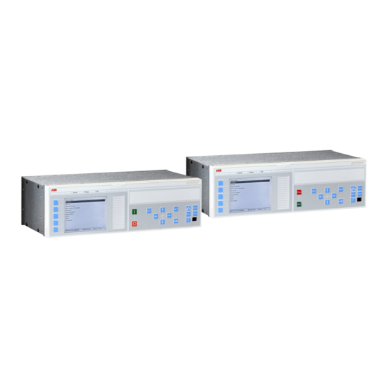
Page 29: 650 Series Overview
The LHMI includes a graphical monochrome display with a resolution of 320 x 240 pixels. The character size can vary. The display view is divided into four basic areas. 650 series Operation manual © Copyright 2013 ABB. All rights reserved... - Page 30 If text, pictures or other items do not fit in the display, a vertical scroll bar appears on the right. The text in content area is truncated from the beginning if it does not fit in the display horizontally. Truncation is indicated with three dots. 650 series Operation manual © Copyright 2013 ABB. All rights reserved...
- Page 31 ANSI12000025 V1 EN-US Figure 5: Function button panel The alarm LED panel shows on request the alarm text labels for the alarm LEDs. Three alarm LED pages are available. 650 series Operation manual © Copyright 2013 ABB. All rights reserved...
-
Page 32: Leds
The keypad also contains programmable push-buttons that can be configured either as menu shortcut or control buttons. 650 series Operation manual © Copyright 2013 ABB. All rights reserved... - Page 33 Table 8: Object control push-buttons Name Description Closing the object. Close The LED indicates the current object state. Opening the object. Open The LED indicates the current object state. 650 series Operation manual © Copyright 2013 ABB. All rights reserved...
- Page 34 Changing the active digit of a parameter when entering a new setting value. Right • Activating the authorization procedure, when the user is not logged in. • Logging out, when the user is currently logged in. 650 series Operation manual © Copyright 2013 ABB. All rights reserved...
-
Page 35: Local Hmi Functionality
The protection indicator LEDs are Normal, Pickup and Trip. Table 12: Normal LED (green) LED state Description Auxiliary supply voltage is disconnected. Normal operation. Flashing Internal fault has occurred. 650 series Operation manual © Copyright 2013 ABB. All rights reserved... - Page 36 LatchedAck-F-S sequence: The activation signal is on, or it is off but the indication has not been acknowledged. • LatchedAck-S-F sequence: The indication has been acknowledged, but the activation signal is still on. 650 series Operation manual © Copyright 2013 ABB. All rights reserved...
-
Page 37: Parameter Management
IP address for the front port is 10.1.150.3. Do not connect the IED front port to a LAN. Connect only a single local PC with PCM600 to the front port. 650 series Operation manual © Copyright 2013 ABB. All rights reserved... -
Page 38: Single-Line Diagram
Single-line diagram is used for bay monitoring and/or control. It shows a graphical presentation of the bay which is configured with PCM600. ANSI11000181 V1 EN-US ANSI11000180 V1 EN-US Figure 9: Single-line diagram example (REC650) 650 series Operation manual © Copyright 2013 ABB. All rights reserved... -
Page 39: Authorization
Can create and load configurations and change settings for the IED and also run commands and manage disturbances INSTALLER Installer Can load configurations and change settings for the IED Table continues on next page 650 series Operation manual © Copyright 2013 ABB. All rights reserved... -
Page 40: Communication
All communication connectors, except for the front port connector, are placed on integrated communication modules. The IED is connected to Ethernet-based communication systems via the RJ-45 connector (10/100BASE-TX) or the fibre-optic multimode LC connector (100BASE-FX). 650 series Operation manual © Copyright 2013 ABB. All rights reserved... -
Page 41: Pcm600 Tool
In addition, it contains code which allows software packages that consume the connectivity package to properly communicate with the protection 650 series Operation manual © Copyright 2013 ABB. All rights reserved... -
Page 42: Cyber Security Guidelines
Setting – Advanced Control – Basic Control – Advanced IEDCmd – Basic IEDCmd – Advanced FileTransfer – Limited DB Access normal Audit log read Setting – Change Setting Group Security Advanced 650 series Operation manual © Copyright 2013 ABB. All rights reserved... - Page 43 For passwords see the Password policies in PCM600. First user created must be appointed the role SECADM to be able to write users, created in PCM600, to the IED. 650 series Operation manual © Copyright 2013 ABB. All rights reserved...
-
Page 44: Ip Ports
Front and Rear refer to the physical front and rear port. The protocol availability on these ports is configurable. ABB recommends using common security measures, like firewalls, up to date anti virus software, etc. to protect the IED and the equipment around it. - Page 45 IP routing is not possible via any of the physical interfaces. Some IP ports are not possible to use in all physical interfaces. ANSI12000172-1-en.vsd ANSI12000172 V1 EN-US Figure 11: Ethernet port used for PCM600 only, front view 650 series Operation manual © Copyright 2013 ABB. All rights reserved...
- Page 46 1MRK 500 096-UUS B 650 series overview IEC12000171-1-en.vsd IEC12000171 V1 EN-US Figure 12: Ethernet port LAN1, rear view COM05 IEC13000021-1-en.vsd IEC13000021 V1 EN-US Figure 13: Ethernet ports LAN1A, LAN1B, rear view COM03 650 series Operation manual © Copyright 2013 ABB. All rights reserved...
-
Page 47: Using The Hmi
5.1.1 Logging on GUID-E0F937A9-78EC-4528-AB34-FD6EC79A7815 v1 Press to activate the logon procedure. The logon is also activated when attempting a password-protected operation. Select the user name by scrolling with 650 series Operation manual © Copyright 2013 ABB. All rights reserved... - Page 48 Enter the character with Upper and lower case letters are also found by scrolling the 255 characters with IEC12000157-2-en.vsd IEC12000157 V2 EN-US Figure 15: Entering the password Passwords are case sensitive. 650 series Operation manual © Copyright 2013 ABB. All rights reserved...
- Page 49 Once a user is created and written into the IED, logon is possible with the password assigned in the tool. If there is no user created, an attempt to log on causes the display to show a corresponding message. 650 series Operation manual © Copyright 2013 ABB. All rights reserved...
-
Page 50: Logging Off
Manual logoff is also possible. Press To confirm logoff, select Yes and press IEC12000159-2-en.vsd IEC12000159 V2 EN-US Figure 18: Logging off • To cancel logoff, press 650 series Operation manual © Copyright 2013 ABB. All rights reserved... -
Page 51: Turning The Display Backlight On
Identifying the device AMU0600422 v7 The IED information includes detailed information about the device, such as revision and serial number. Select Main menu/Diagnostics/IED Status/Product identifiers. Select a submenu with 650 series Operation manual © Copyright 2013 ABB. All rights reserved... -
Page 52: Adjusting The Display Contrast
AMU0600410 v6 Adjust the display contrast anywhere in the menu structure to obtain optimal readability. • To increase the contrast, press simultaneously • To decrease the contrast, press simultaneously 650 series Operation manual © Copyright 2013 ABB. All rights reserved... -
Page 53: Changing The Local Hmi Language
To move downwards in the menu tree, press • To move upwards in the menu tree, press • To enter setting mode, press • To leave setting mode without saving, press 650 series Operation manual © Copyright 2013 ABB. All rights reserved... -
Page 54: Menu Structure
5.1.8.3 Changing the default view GUID-068D31CD-D53C-48F4-817C-EAD8E33C0A0C v7 The default view of the display is Main menu unless set otherwise. 650 series Operation manual © Copyright 2013 ABB. All rights reserved... -
Page 55: Using Function Buttons
The panel is also closed after pressing a function button configured for a menu shortcut. The function buttons are configured with PCM600. For more information, see PCM600 documentation. 650 series Operation manual © Copyright 2013 ABB. All rights reserved... -
Page 56: Using The Single-Line Diagram
Select the single-line diagram for the default view in Main menu/ Configuration/HMI/Screen/SCREEN:1/DefaultScreen. 5.1.11 Browsing setting values GUID-81116DC8-1E66-4144-920F-07C79F1C76B0 v3 Select Main menu/Settings/IED Settings and press Press and then to activate the setting group number selection. 650 series Operation manual © Copyright 2013 ABB. All rights reserved... -
Page 57: Editing Values
Editing values GUID-8BF4B799-54A7-4224-BC11-0BCE3129B811 v3 • To edit values, log in with the appropriate user rights. If the user rights are not sufficient for editing values, the login dialog opens. 650 series Operation manual © Copyright 2013 ABB. All rights reserved... -
Page 58: Editing Numerical Values
Another press of sets the value to the lower or higher limit. The symbol in front of the value is ↕, when the previous value is shown. 650 series Operation manual © Copyright 2013 ABB. All rights reserved... -
Page 59: Editing String Values
If there is a need to change the time setting in the LHMI (Main menu/Configuration/Time/System time/SYSTEMTIME:1) the change will take affect immediately. To confirm the new setting press . To remove the change, press 650 series Operation manual © Copyright 2013 ABB. All rights reserved... -
Page 60: Saving Settings
Events and alarms assigned to alarm LEDs are cleared with the Clear button as well. Press to activate the Clear view. 650 series Operation manual © Copyright 2013 ABB. All rights reserved... -
Page 61: Using The Local Hmi Help
To close the help, press The help dialog is also closed when the display timeout expires. IEC13000065-1-en.vsd IEC13000065 V1 EN-US Figure 32: Help menu 650 series Operation manual © Copyright 2013 ABB. All rights reserved... -
Page 63: Ied Operation
Document the disturbance before clearing the information from the IED. Only authorized and skilled personnel should analyze possible errors and decide on further actions. Otherwise, stored disturbance data can be lost. 650 series Operation manual © Copyright 2013 ABB. All rights reserved... -
Page 64: Dfr Recording Triggering
Document all the recorded data from the IED before resetting the tripping and IED lockout functions. IED parameterization GUID-F3F7C6D0-1A2B-487B-8291-C5C346F56C3E v7 IED parameters are set via the LHMI or PCM600. 650 series Operation manual © Copyright 2013 ABB. All rights reserved... -
Page 65: Ied Settings For Ied Functionality
IED settings can be designed for various operation conditions by defining different setting values to different setting groups. The active setting group can be changed by the IED application or manually via the LHMI or PCM600. 650 series Operation manual © Copyright 2013 ABB. All rights reserved... -
Page 67: Operating Procedures
The message contains the same information that is available for disturbance recordings. Press to see more detailed information. Press to close the auto-indication message without clearing it or press to activate the Clear view and to clear messages. 650 series Operation manual © Copyright 2013 ABB. All rights reserved... -
Page 68: Monitoring Alarm Data
Press to open a dialog box that shows more detailed information about the selected alarm. 650 series Operation manual © Copyright 2013 ABB. All rights reserved... -
Page 69: Monitoring An Internal Ied Fault
Figure 35: Alarm data 7.1.1.3 Monitoring an internal IED fault GUID-67B6F8FD-3E2B-4EA6-8822-539F7FA3678B v2 The flashing green LED indicates an internal IED fault. The fault messages are found in the LHMI menu. 650 series Operation manual © Copyright 2013 ABB. All rights reserved... -
Page 70: Monitoring Condition Monitoring Data
Measured values AMU0600431 v5 Measured values can be accessed through the LHMI. 7.1.2.2 Using the local HMI for monitoring AMU0600432 v5 Select Main menu/Measurements to monitor measured and calculated values. 650 series Operation manual © Copyright 2013 ABB. All rights reserved... -
Page 71: Recorded Data
Select Main menu/Disturbance records. Select Manual Trig with Press to execute manual triggering. A071208 V3 EN-US Figure 37: Manual triggering The disturbance recorder is now triggered. 650 series Operation manual © Copyright 2013 ABB. All rights reserved... -
Page 72: Monitoring Disturbance Recorder Data
A list of detail categories is displayed. GUID-CECFCDAB-06F4-4C5E-8244-6E43E89CF47C V2 EN-US Figure 39: Disturbance record data categories To select a category and view the items under it, press and then 650 series Operation manual © Copyright 2013 ABB. All rights reserved... -
Page 73: Controlling And Uploading Dfr Recorder Data
The event list is not updated dynamically. To update the list, leave the Events menu and then select it again. 7.1.4 Remote monitoring GUID-4813E67F-5F17-48A7-A083-27E006A5B386 v1 The IED supports comprehensive remote monitoring. 650 series Operation manual © Copyright 2013 ABB. All rights reserved... -
Page 74: Monitoring The Ied Remotely
Switch object is in substituted state. Switch object is interlocked. Press to open or to close the object. ANSI12000007-1-en.vsd ANSI12000007 V1 EN-US Figure 41: Selecting an object Press to confirm the operation. 650 series Operation manual © Copyright 2013 ABB. All rights reserved... -
Page 75: Resetting The Ied
Events and alarms assigned to alarm LEDs can also be cleared with the Clear button. Press to activate the Clear view. All the items that can be cleared are shown. 650 series Operation manual © Copyright 2013 ABB. All rights reserved... -
Page 76: Changing The Ied Functionality
IED settings are planned in advance for different operation conditions by calculating setting values to different setting groups. The active setting group can be changed manually from the menu or by the PCM600 tool.. Select Main menu/Settings/Activate setting group/SETGRPS:1 and press 650 series Operation manual © Copyright 2013 ABB. All rights reserved... -
Page 77: Browsing And Editing Setting Group Values
Remember to document the changes you make. 7.4.1.2 Browsing and editing setting group values GUID-5624E7E4-1D14-469A-BF86-8BD560B72F9D v3 Select Main menu/Settings/IED setting and press Setting group 1 is the default setting group to be edited. 650 series Operation manual © Copyright 2013 ABB. All rights reserved... - Page 78 Categories available in the list depend on the configuration configured with PCM600. GUID-18645E71-B6E8-401B-B24E-A8D204876ACF V1 EN-US Figure 48: Selecting the function category To browse the function blocks, scroll the list with 650 series Operation manual © Copyright 2013 ABB. All rights reserved...
- Page 79 In case of a setting group parameter, the editing dialog shows the value of the setting in all available setting groups, but the user can edit only the value in the selected setting group. The active setting group is marked with an asterisk *. 650 series Operation manual © Copyright 2013 ABB. All rights reserved...
-
Page 80: Activating Leds
Confirm the change with 7.4.2 Activating LEDs GUID-C63971C7-EDC8-40BA-B53B-7377AA33FCC5 v5 To activate the LEDs, they must be configured with PCM600. Select Main menu/Configuration/HMI/LEDs and press IEC13000056-1-en.vsd IEC13000056 V1 EN-US Figure 51: Alarm groups 650 series Operation manual © Copyright 2013 ABB. All rights reserved... - Page 81 Select an Alarm LED with Press to confirm the selection and to change the Alarm LED mode. Press to change the value and to confirm the selection. For more information, see PCM600 documentation. 650 series Operation manual © Copyright 2013 ABB. All rights reserved...
-
Page 83: Troubleshooting
Inspect the IED visually. • Inspect the IED visually to find any physical error causes. • If you can find some obvious physical damage, contact ABB for repair or replacement actions. Check whether the error is external or internal. •... -
Page 84: Checking The Time Synchronization
The list is updated by leaving the Internal events menu and then selecting it again. The current status of the internal fault signals can also be checked via the LHMI in Main menu/Diagnostics/IED status. 650 series Operation manual © Copyright 2013 ABB. All rights reserved... -
Page 85: Warnings
Additional information Warning IEC 61850 has not IEC 61850 Error succeeded in some actions such as reading the configuration file, startup etc. Warning Error in DNP3 DNP3 Error communication. 650 series Operation manual © Copyright 2013 ABB. All rights reserved... -
Page 86: Additional Indications
Check the current or voltage measurements and their phase information from Main menu/ Measurements/Analog primary values or Analog secondary values. • Check that the phase information and phase shift between phases is correct. • Correct the wiring if needed. 650 series Operation manual © Copyright 2013 ABB. All rights reserved... - Page 87 GUID-BBAEAF55-8D01-4711-A71D-BBC76B60BA3D V1 EN-US Figure 52: Testing output contacts using the voltage drop method Contact current 2 Contact voltage drop 3 Load 4 Supply voltage 650 series Operation manual © Copyright 2013 ABB. All rights reserved...
- Page 88 0 of the output, and in PCM600 a lit or dimmed diode. The second signal is the status Forced or Normal or Forced. Forced status is only achieved when the BO is set to operated on the LHMI. 650 series Operation manual © Copyright 2013 ABB. All rights reserved...
- Page 89 As a result, practically the full voltage is available at the load. 650 series Operation manual © Copyright 2013 ABB. All rights reserved...
-
Page 91: Glossary
Standard Common Format for Transient Data Exchange format for Disturbance recorder according to IEEE/ANSI C37.111, 1999 / IEC60255-24 Cause of transmission Central processing unit Carrier receive Cyclic redundancy check CROB Control relay output block 650 series Operation manual © Copyright 2013 ABB. All rights reserved... - Page 92 FOX 512/515 Access multiplexer FOX 6Plus Compact time-division multiplexer for the transmission of up to seven duplex channels of digital data over optical fibers File Transfer Protocal Function type 650 series Operation manual © Copyright 2013 ABB. All rights reserved...
- Page 93 1. Internet protocol. The network layer for the TCP/IP protocol suite widely used on Ethernet networks. IP is a connectionless, best-effort packet- switching protocol. It provides packet routing, fragmentation and reassembly through the data link layer. 650 series Operation manual © Copyright 2013 ABB. All rights reserved...
- Page 94 Process bus Bus or LAN used at the process level, that is, in near proximity to the measured and/or controlled components Power supply module Parameter setting tool within PCM600 650 series Operation manual © Copyright 2013 ABB. All rights reserved...
- Page 95 Ethernet protocols incorporated into 4.2BSD Unix. TCP/IP was developed by DARPA for Internet working and encompasses both network layer and transport layer protocols. While TCP and IP specify two protocols 650 series Operation manual © Copyright 2013 ABB. All rights reserved...
- Page 96 Three times zero-sequence current. Often referred to as the residual or the ground-fault current Three times the zero sequence voltage. Often referred to as the residual voltage or the neutral point voltage 650 series Operation manual © Copyright 2013 ABB. All rights reserved...
- Page 98 Grid Automation Products SE-721 59 Västerås, Sweden SE-721 59 Västerås, Sweden Phone +46 (0) 21 32 50 00 Phone +46 (0) 21 32 50 00 Scan this QR code to visit our website www.abb.com/protection-control © Copyright 2013 ABB. All rights reserved.