Advertisement
Quick Links
TABLE OF CONTENTS
1 Warning -------------------------------------------------------------- 2
2 Specifications ----------------------------------------------------- 2
3 Troubleshooting Guide ----------------------------------------- 2
4 Disassembly and Assembly Instructions ---------------- 4
5 Exploded View and Replacement Parts List ------------ 8
Model No.
Europe
PAGE
© Panasonic Corporation 2019. All rights reserved.
Unauthorized copying and distribution is a violation
of law.
ORDER NO. PTD1911E07CE
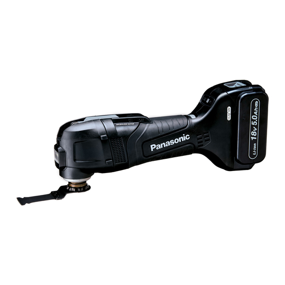
Cordless Multi-Tool
EY46A5
PAGE
Advertisement

Summary of Contents for Panasonic EY46A5
-
Page 1: Table Of Contents
2 Specifications ----------------------------------------------------- 2 3 Troubleshooting Guide ----------------------------------------- 2 4 Disassembly and Assembly Instructions ---------------- 4 5 Exploded View and Replacement Parts List ------------ 8 © Panasonic Corporation 2019. All rights reserved. Unauthorized copying and distribution is a violation of law. -
Page 2: Warning
1 Warning Caution: • Pb free solder has a higher melting point that standard solder; Typically the melting point is 50 - 70 °F (30 - 40 °C) higher. Please use a soldering iron with temperature control and adjust it to 750 ± 20 °F (400 ± 10 °C). In case of using high temperature soldering iron, please be careful not to heat too long. - Page 3 3.2. Trial Operation (after checking Troubleshooting Guide). 3.2.1. Assembly • Confirm if there is no gap between housing A and B by pinching lead wires. • Check that the frequency adjustment dial can be adjusted from 1 to 6. • Mount the blade release lever to the main unit, and confirm that the fixing bolt is securely tightened. •...
-
Page 4: Disassembly And Assembly Instructions
4 Disassembly and Assembly Instructions * To reduce the risk of injury, always remove battery pack before removing/installing the tool. * To assemble the tool, start with 8 and proceed to 1. 4.1. Disassembly 1. Remove 4 torx screws. 2. Remove the cover. Note: (When Assembling) Pay attention to avoid pinching of lead wires. - Page 5 5. Remove the rotor assembly. Note: (When Assembling) Mount the rotor assembly to the gear case unit, and then install them to the stator. 6. Remove the fan cover. Note: (When Assembling) The protruding part on the fan cover must be placed on lead wire side.
- Page 6 8. Remove the switch nob and display plate from the housing. Note: (When Assembling) Set the frequency adjustment dial at “6”.
- Page 7 4.2. Wiring and Assembly Points...
-
Page 8: Exploded View And Replacement Parts List
5 Exploded View and Replacement Parts List Model No. : EY46A5 Exploded View... - Page 9 Model No. : EY46A5 Parts List Ref. Change Safety Part No. Part Name & Description Q'ty Remarks WEY46A5K3102 HOUSING AB SET WEY46A5K3201 BLADE RELEASE LEVER SET WEY46A5K3301 DISPLAY PLATE WEY46A5K3401 HEAD COVER AB SET WEY46A5L0101 FIXING BOLT WEY46A5L1201 GEAR CASE UNIT...


