Advertisement
Quick Links
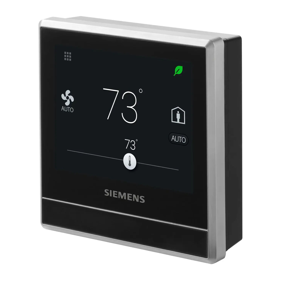
Smart Thermostat
RDS120
A6V10807603_enUS_a
2018-04-12
Advanced cloud connected thermostat for light commercial and residential
applications
Controls conventional HVAC systems up to 3H/2C and heat pumps up to 4H/2C
Easy to read, backlit, auto-dimming 3.5" color LCD touch
Intuitive remote user control using Apple iOS and Android mobile phone
applications
One-touch green leaf button to maximize energy efficiency
Built-in Volatile Organic Compounds (VOC) sensor enables ventilation strategies
for optimum indoor air quality
Built-in humidity sensor
Built-in occupancy sensor and window / door contact enables smart occupancy
control
Full, easy to program user schedule
Siemens AG
Building Technologies
Advertisement

Related Manuals for Siemens RDS120


Summary of Contents for Siemens RDS120
- Page 1 Smart Thermostat RDS120 Advanced cloud connected thermostat for light commercial and residential applications Controls conventional HVAC systems up to 3H/2C and heat pumps up to 4H/2C Easy to read, backlit, auto-dimming 3.5” color LCD touch Intuitive remote user control using Apple iOS and Android mobile phone...
- Page 2 Monitor indoor air quality: “Good”, “Okay”, “Poor” Data security with Siemens Cloud Computing Platform Application The RDS120 is designed to control Heat Pump or Conventional HVAC heating and cooling applications. It can control up to three stages of heating and two stages of cooling in Siemens...
- Page 3 Temperature setpoint slider. Icon color changes as setpoint is changed: Slider changes to red when heating relay is energized. Slider changes to blue when cooling relay is energized. If system has reached setpoint and is idle, the slider color stays white. Siemens A6V10807603_enUS_a Building Technologies 2018-04-12...
- Page 4 Room temperature NOTE: Idle mode display will vary based on system configuration. Ordering Information Model Number Orderable Part Number Description RDS120 S55772-T101 Room Thermostat Contents Items Quantity Thermostat (front and rear) Metal mounting plates (small & large)
- Page 5 (T+r.h.) 149-991 - Duct-mount including temperature Indoor Air Quality Sensors - CO QPA2000 149-910 - VOC + CO QPA2002 149-910 QPA2002D 149-910 - CO QPA2060 x(CO +T) 149-910 including QPA2060D x(CO +T) 149-910 temperature Siemens A6V10807603_enUS_a Building Technologies 2018-04-12...
- Page 6 QPM2160 x(CO +T) 149-909 - Duct-mount including temperature * The documents can be downloaded from Siemens US Download Center by specifying the product number as shown in the above table. 1) With digital display Replacement Part Description Model Number Orderable Part...
- Page 7 6]) to configure your device. Commissioning includes the following: Internet connection Application setup Account registration and device pairing NOTE: Before configuring your thermostat, make sure you have Internet connection, a valid email address, and a smartphone. Siemens A6V10807603_enUS_a Building Technologies 2018-04-12...
- Page 8 L'exploitation est autorisee aux deux conditions suivantes : (1) l'appareil ne doit pas produire de brouillage, et (2) l'utilisateur de l'appareil doit accepter tout brouillage radioelectrique subi, meme si le brouillage est susceptible d'en compromettre le fonctionnement. Siemens A6V10807603_enUS_a Building Technologies...
- Page 9 This device complies with part 15 of the FCC Rules. Operation is subject to the following two conditions: (1) This device may not cause harmful interference, and (2) this device must accept any interference received, including interference that may cause undesired operation. Siemens A6V10807603_enUS_a Building Technologies...
- Page 10 Power consumption Max. 9 VA Max. power supply current 4 A current limited Radio Data Radio Parameter Frequency band 2.4 to 2.4835 GHz Maximum radio-frequency power 18 dBm WLAN standard IEEE 802.11b/g/n (HT20) WLAN channel 1-11 Siemens A6V10807603_enUS_a Building Technologies 2018-04-12...
- Page 11 Max. 20 thermostats per switch - Input function Selectable Outputs Relay Contact Capacity Voltage AC 24 V (±20%) Current Min. 0.02 A, Max. 1 A per output Operational Data Setpoint Range 45 to 95 °F (7…35 Siemens A6V10807603_enUS_a Building Technologies 2018-04-12...
- Page 12 Sensor Detection Range A: The width of each cell, 80 cm (31 in). B: The thermostat. C: The height of each cell, 80 cm (31 in). D: The area that the PIR sensor can detect. Siemens A6V10807603_enUS_a Building Technologies 2018-04-12...
- Page 13 Authorization Number of TRA: ER54733/17 Environmental compatibility The product environmental declaration A5W90003412 contains data on environmentally compatible product design and assessments (RoHS compliance, materials composition, packaging, environmental benefit, disposal). *) The documents can be downloaded from http://siemens.com/bt/download. Siemens A6V10807603_enUS_a Building Technologies 2018-04-12...
- Page 14 Y1, Y2 Stages 1 and 2 cooling in conventional system or Stages 1 and 2 compressor in heat pump system X1, X2 Configurable input Common for X1/X2 inputs Siemens A6V10807603_enUS_a Building Technologies 2018-04-12...
- Page 15 C. If separate transformers are used for heating and cooling systems, remove jumper RH-RC. Connect cooling AC 24 V to terminal RC, neutral to terminal C and heating AC 24 V to terminal RH. Siemens A6V10807603_enUS_a Building Technologies...
- Page 16 Changes Section Pages April 2018 32.2.16 New document Issued by © Siemens Industry, Inc., 2018 Siemens Industry, Inc. Technical specifications and availability subject to change without notice. Building Technologies Division 1000 Deerfield Pkwy Buffalo Grove IL 60089 Tel. +1 847-215-1000...