Advertisement
Quick Links
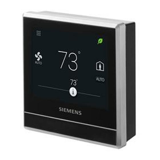
Smart Thermostat
RDS120-B Technical Instructions
A6V11727385
06/20/2019
Advanced cloud connected thermostat for light commercial and residential
applications
•
BACnet over IP Certified
•
Controls conventional HVAC systems up to 3H/2C and heat pumps up to 4H/2C
•
Easy to read, backlit, auto-dimming 3.5" color LCD touch
•
Intuitive remote user control using Apple iOS and Android mobile phone
applications
•
One-touch green leaf button to maximize energy efficiency
•
Built-in Volatile Organic Compounds (VOC) sensor enables ventilation strategies
for optimum indoor air quality
•
Built-in humidity sensor
•
Built-in occupancy sensor and window / door contact enables smart occupancy
control
•
Full, easy to program user schedule
Smart Infrastructure
Advertisement

Related Manuals for Siemens RDS120-B


Summary of Contents for Siemens RDS120-B
- Page 1 Smart Thermostat RDS120-B Technical Instructions Advanced cloud connected thermostat for light commercial and residential applications • BACnet over IP Certified • Controls conventional HVAC systems up to 3H/2C and heat pumps up to 4H/2C • Easy to read, backlit, auto-dimming 3.5” color LCD touch •...
- Page 2 ● Monitor indoor air quality: “Good”, “Okay”, “Poor” ● Data security with Siemens Cloud Computing Platform Application The RDS120 is designed to control Heat Pump or Conventional HVAC heating and cooling applications. It can control up to three stages of heating and two stages of cooling in conventional systems and up to two compressors and two stages of auxiliary heat in heat pump systems.
- Page 3 Slider changes to red when heating relay is energized. ● Slider changes to blue when cooling relay is energized. ● If system has reached setpoint and is idle, the slider color stays white. Siemens Industry, Inc. A6V11727385 Smart Infrastructure 06/20/2019...
- Page 4 RDS120-B Room Thermostat Contents Items Quantity Thermostat (front and rear) Metal mounting plates (small & large) Plastic frame Set of screws and drywall anchors Quick guide Mounting instructions Wiring decals Activation code decal Siemens Industry, Inc. A6V11727385 Smart Infrastructure 06/20/2019...
- Page 5 - VOC + CO QPA2002 149-910 QPA2002D 149-910 - CO QPA2060 x(CO 149-910 including QPA2060D x(CO 149-910 temperature - Duct-mount QPM2100 149-909 - Duct-mount QPM2102 149-909 VOC + CO - Duct-mount QPM2160 x(CO 149-909 including temperature Siemens Industry, Inc. A6V11727385 Smart Infrastructure 06/20/2019...
- Page 6 * The documents can be downloaded from Siemens US Download Center by specifying the product number as shown in the above table. 1) With digital display Replacement Part Description Model Orderable Number Part Number Plastic trim plate and metal mounting ARG100.01...
- Page 7 ● Internet connection ● Application setup ● Account registration and device pairing NOTE: Before configuring your thermostat, make sure you have Internet connection, a valid email address, and a smartphone. Operation Operating System Siemens Industry, Inc. A6V11727385 Smart Infrastructure 06/20/2019...
- Page 8 L'exploitation est autorisee aux deux conditions suivantes : (1) l'appareil ne doit pas produire de brouillage, et (2) l'utilisateur de l'appareil doit accepter tout brouillage radioelectrique subi, meme si le brouillage est susceptible d'en compromettre le fonctionnement. Siemens Industry, Inc. A6V11727385 Smart Infrastructure 06/20/2019...
- Page 9 This device complies with part 15 of the FCC Rules. Operation is subject to the following two conditions: (1) This device may not cause harmful interference, and (2) this device must accept any interference received, including interference that may cause undesired operation. Siemens Industry, Inc. A6V11727385 Smart Infrastructure...
- Page 10 - Humidity range (default) 0 to 100% - CO range (default) 0 to 2000 ppm Digital contacts - Operating action Selectable N.O./N.C. - Contact sensing DC 14 to 40 V, 8 mA (typical) Siemens Industry, Inc. A6V11727385 Smart Infrastructure 06/20/2019...
- Page 11 Connections Interfaces Micro USB A service port is provided for firmware upgrade and on-site diagnosis Wiring Connections Screw terminals Solid wires or prepared stranded wires: Max. 1 × 16 to 20 AWG Siemens Industry, Inc. A6V11727385 Smart Infrastructure 06/20/2019...
- Page 12 Mechanical ambient conditions Storage as per EN 60721-3-1 Class 1M2 Transport as per EN 60721-3-2 Class 2M2 Operation as per EN 60721-3-3 Class 3M2 Standards, Directives and Approvals EU conformity (CE) A5W90002476 RCM conformity A5W90002477 Siemens Industry, Inc. A6V11727385 Smart Infrastructure 06/20/2019...
- Page 13 The product environmental declaration A5W90003412 contains data on environmentally compatible product design and assessments (RoHS compliance, materials composition, packaging, environmental benefit, disposal). *) The documents can be downloaded from http://siemens.com/bt/download. General Data General H 3.58” × W 3.58” × D 1.02”...
- Page 14 C. If separate transformers are used for heating and cooling systems, remove jumper RH-RC. Connect cooling 24 Vac to terminal RC, neutral to terminal C and heating 24 Vac to terminal RH. Siemens Industry, Inc. A6V11727385 Smart Infrastructure...
- Page 15 Dimensions Siemens Industry, Inc. A6V11727385 Smart Infrastructure 06/20/2019...
- Page 16 Issued by © Siemens Industry, Inc., 2019 Siemens Industry, Inc. Technical specifications and availability subject to change without notice. Smart Infrastructure 1000 Deerfield Pkwy Buffalo Grove IL 60089 Tel. +1 847-215-1000 Siemens Industry, Inc. A6V11727385 Smart Infrastructure 06/20/2019 Document ID...