Table of Contents
Advertisement
Quick Links
Advertisement
Table of Contents

Related Manuals for ABB M2302


Summary of Contents for ABB M2302
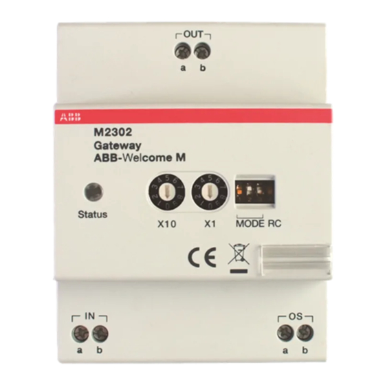
- Page 1 VER:1.1 │ │ 25.09.2015 ABB-Welcome Pos : 2 /Di nA4 - Anleitung en Online/Inhalt/KN X/D oorEntr y/83220- AP- xxx/Titelbl att - 83220-AP- xxx - ABB @ 19\mod_1323249806476_15.doc x @ 111084 @ @ 1 M2302 Gateway === Ende der Liste fü r T extmar ke Cover ===...
-
Page 2: Table Of Contents
Pos : 4 /Busch-J aeger (Neus truktur)/M odul-Str uktur/Online-Dokumentation/Inhal ts verz eic hnis (--> Fü r alle D okumente <--)/Inhalts verz eichnis @ 19\mod_1320649044386_15.doc x @ 109653 @ @ 1 Safety ......................3 Intended use ....................3 Environment ....................3 ABB devices ................. 3 Operation ....................... 5 Control elements ................5 Operating modes ................6 4.2.1... -
Page 3: Safety
ABB devices Pos : 13 /Busc h-J aeg er (Neustr uktur)/Modul- Struktur /Online-Dokumentati on/U mwel t (--> Fü r alle D okumente <--)/Hinweis e/Hi nweis - U mwelt - ABB El ektr ogeräte @ 19\mod_1323162745839_15.doc x @ 110867 @ @ 1 All packaging materials and devices from ABB bear the markings and test seals for proper disposal. - Page 4 ABB-Welcome Environment ABB products meet the legal requirements, in particular the laws governing electronic and electrical devices and the REACH ordinance. (EU-Directive 2002/96/EG WEEE and 2002/95/EG RoHS) (EU-REACH ordinance and law for the implementation of the ordinance (EG) No.1907/2006) — 4 —...
-
Page 5: Operation
ABB-Welcome Operation Pos : 18 /DinA4 - Anl eitungen Onli ne/Ueberschriften/1./Bedi enung @ 18\mod_1302613924165_15.doc x @ 103365 @ 1 @ 1 Operation Pos : 19 /DinA4 - Anl eitungen Onli ne/Ueberschriften/2./Nor maler Betrieb @ 18\mod_1302768820965_15.doc x @ 103540 @ 2 @ 1 Control elements Pos : 20 /DinA4 - Anl eitungen Onli ne/Ueberschriften/3./Bedi enel emente @ 20\mod_1323260220559_15.doc x @ 111647 @ 3 @ 1... -
Page 6: Operating Modes
ABB-Welcome Operation Pos : 26 /DinA4 - Anl eitungen Onli ne/Ueberschriften/2./Bedi enaktionen @ 20\mod_1323262294281_15.doc x @ 111911 @ 2 @ 1 Operating modes Pos : 71 /DinA4 - Anl eitungen Onli ne/Ueberschriften/3./Absc hlus s widerstand @ 19\mod_1321958079906_15.doc x @ 110083 @ 3 @ 1 Pos : 72 /DinA4 - Anl eitungen Onli ne/Inhalt/KN X/D oor Entr y/Bedienung/Absc hl uss widerstand setzen 83220-AP- xxx @ 19\mod_1310723392369_15.doc x @ 107841 @ @ 1... - Page 7 ABB-Welcome Operation Enable one building as an independent sub-system (outdoor station(s)/guard unit(s) can be connected). Up to 60 such systems are supported within the whole system. The gateway address is equal to the riser number. Fig. 3: Building gateway Wiring diagram: Fig.
-
Page 8: Floor Gateway
ABB-Welcome Operation 4.2.2 Floor gateway Fig. 5: Floor gateway Functions 1->OFF, 2->OFF, 3->ON — 8 —... - Page 9 ABB-Welcome Operation Enable a multi-apartment as an independent sub-system (another outdoor station can be connected, for example in front of the door of the floor with the multi-apartment). The gateway address is equal to the minimum address of the indoor station inside the sub-system.
- Page 10 ABB-Welcome Operation Wiring diagram: Fig. 7: Floor gateway If using pushbutton outdoor station as a gate station, f loor gateway is available for this kind of use case. In following example, an outdoor station is mounted at the gate entrance with which all six apartments can be called.
- Page 11 Apartment 01 A Apartment 02 B Apartment 02 B Apartment 03 C Apartment 03 C Apartment 04 D Apartment 04 A Apartment 05 E Apartment 05 B Apartment 06 F Apartment 06 C M2302 M2302 X10 X1 X10 X1 — 11 —...
-
Page 12: Apartment Gateway
ABB-Welcome Operation 4.2.3 Apartment gateway Fig. 8: Apartment gateway Functions 1->OFF, 2->ON, 3->OFF — 12 —... - Page 13 ABB-Welcome Operation Enable one apartment as an independent sub-system (The 2nd confirmed outdoor station can be connected). Up to 99 such systems can be supported within the whole system. The gateway address is equal to the apartment number. Fig. 9: Apartment gateway —...
- Page 14 ABB-Welcome Operation Wiring diagram: Fig. 10: Apartment gateway — 14 —...
-
Page 15: Additional Power Supply Mode
ABB-Welcome Operation 4.2.4 Additional power supply mode Fig. 11: Additional power supply mode Functions 1->OFF, 2->ON, 3->ON — 15 —... - Page 16 ABB-Welcome Operation Enable an additional power source for systems with a system controller. ★ Using gateway + system controller as auxiliary power supply to ★ connect to other indoor stations in the same building, when one system controller can’t cover all consmer units.
- Page 17 ABB-Welcome Operation Wiring diagram: Fig. 13: Additional power supply mode — 17 —...
-
Page 18: Line Amplifier
ABB-Welcome Operation 4.2.5 Line amplifier Fig. 14: Line amplifier Functions 1->ON, 2->OFF, 3->OFF Strengthen the video signal and extend transmission. For increased distance please refer to ABB-Welcome system manual. Fig. 15: Line amplifier — 18 —... - Page 19 ABB-Welcome Operation Wiring diagram: Fig. 16: Line amplifier Pos : 75 /Busc h-J aeg er (Neustr uktur)/Modul- Struktur /Online-Dokumentati on/Steuermodul e - Onli ne-D okumentation (--> F ü r all e D okumente <--)/++++++++++++ Seitenumbruc h ++++++++++++ @ 9\mod_1268898668093_0.doc x @ 52149 @ @ 1...
-
Page 20: Technical Data
ABB-Welcome Technical data Pos : 76 /DinA4 - Anl eitungen Onli ne/Ueberschriften/1./Tec hnisc he D aten @ 18\mod_1302615863001_15.doc x @ 103416 @ 1 @ 1 Technical data Pos : 77 /DinA4 - Anl eitungen Onli ne/Inhalt/KN X/D oor Entr y/83220-AP- xxx/T ec hnische D aten - 83220-AP- xxx @ 18\mod_1303212854559_15.doc x @ 103705 @ @ 1... -
Page 21: Mounting/Installation
ABB-Welcome Mounting/Installation Pos : 79 /Busc h-J aeg er (Neustr uktur)/Modul- Struktur /Online-Dokumentati on/Übersc hriften (--> Fü r alle D okumente <--)/1. Ebene/M - O/Montage / Installation @ 18\mod_1302613966111_15.doc x @ 103373 @ 1 @ 1 Mounting/Installation Pos : 80 /Busc h-J aeg er (Neustr uktur)/Modul- Struktur /Online-Dokumentati on/Sic herheit (--> Fü r alle Dokumente <--)/Warnhinweis e/Sic herheit - Ni eders pannungs- und 230 V-Leitungen @ 18 \mod_1302617821491_15.doc x @ 103465 @ @ 1... -
Page 22: General Installation Instructions
Pos : 85.1 /DinA4 - Anl eitungen Onli ne/Inhalt/KN X/DoorEntr y/83220-AP- xxx/M ontag e - M odul e/Montage - Montagedose -- 83220-AP- xxx @ 19\mod_1323250406848_15.doc x @ 111098 @ @ 1 The device M2302 must only be installed on mounting rails according to DIN EN 500022. - Page 23 We reserve the right to make technical changes at any time as well as changes in the content of this document without prior notice. The detailed specifications agreed to at the time of ordering apply to all orders. ABB accepts no responsibility for possible errors or incompleteness in this document.