
Related Manuals for Epson S5U1C31D50T1


Summary of Contents for Epson S5U1C31D50T1
- Page 1 CMOS 32-BIT SINGLE CHIP MICROCONTROLLER S5U1C31D50T1 Manual (S1C31D50 Evaluation Board) Rev.2.0...
- Page 2 2. This evaluation board/kit or development tool is intended for use by an electronics engineer and is not a consumer product. The user should use it properly and in a safe manner. Seiko Epson dose not assume any responsibility or liability of any kind of damage and/or fire coursed by the use of it. The user should cease to use it when any abnormal issue occurs even during proper and safe use.
-
Page 3: Table Of Contents
Power Supply ..........................7 Audio Amplifier ........................... 8 4. Usage ........................10 Running Demo Software ......................10 Debugging Software ........................ 11 Appendix A Circuit Diagrams ..................13 Appendix B Parts List ....................17 Revision History ......................18 Seiko Epson Corporation S5U1C31D50T1 Manual (Rev.2.0) -
Page 4: Overview
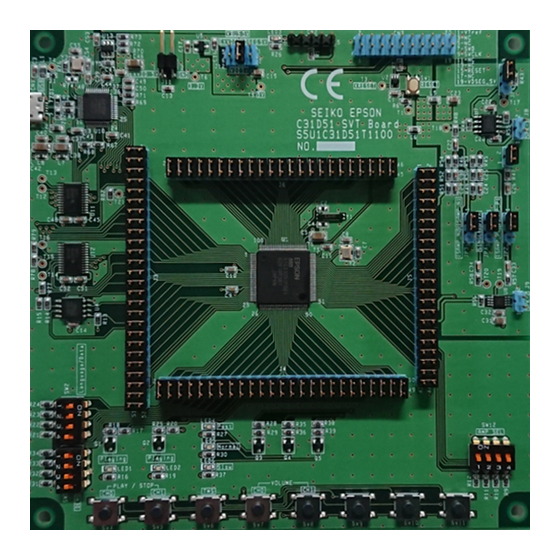
1. Overview Overview S5U1C31D50T1(S1C31D50 Evaluation Board) is an evaluation board for the Seiko Epson single-chip microcontroller S1C31D50. The board comes with a speaker connection cable. Figure 1.1 shows the external view of S5U1C31D50T1. Figure 1.1 S5U1C31D50T1 External View Seiko Epson Corporation S5U1C31D50T1 Manual (Rev.2.0) -
Page 5: Name And Function Of Each Part
2. Name and Function of Each Part Name and Function of Each Part The S5U1C31D50T1 board has the various parts. Table 2.1 lists the main parts on the board. Also Figure 2.1 shows the layout of the parts on the board. - Page 6 USB to Serial Class-AB Amplifier Converter Micro-USB Sound output Connector connector for Class-AB Amp. S1C31D50 Sound output QSPI Flash connector Memory for Class-D Amp. Class-D Amplifier DIP Switches Push Switches Figure 2.1 Layout of Main Parts Seiko Epson Corporation S5U1C31D50T1 Manual (Rev.2.0)
-
Page 7: Settings
3. Settings Settings 3.1 Jumpers Although the S5U1C31D50T1 board is shipped with the jumpers set to an operable state, please check to see if they have been set correctly as shown below. Table 3.1.1 JP5 Jumper Setting Connector: JP5 Pin No. - Page 8 27–28 Short 7–8 Short 29–30 Short 9–10 Short 31–32 Short 11–12 Short 33–34 Short 13–14 Short 35–36 Short 15–16 Short 37–38 Short 17–18 Short 39–40 Short 19–20 Short 41–42 Short 21–22 Short 43–44 Short Seiko Epson Corporation S5U1C31D50T1 Manual (Rev.2.0)
- Page 9 Short 33–34 Short 11–12 Short 35–36 Short 13–14 Short 37–38 Short 15–16 Short 39–40 Short 17–18 Short 41–42 Short 19–20 Short 43–44 Short 21–22 Short 45–46 Short 23–24 Short Figure 3.1.1 Layout of Jumpers Seiko Epson Corporation S5U1C31D50T1 Manual (Rev.2.0)
-
Page 10: Power Supply
3.2 Power Supply The power supply can be selected from among three sources shown below by setting the J12 jumper, T2 and T5 pins. Make sure of the jumper and the pins settings before using the S5U1C31D50T1 board. • External: Power is supplied to J11 from an external power such as the stabilized power supply. -
Page 11: Audio Amplifier
3. Settings 3.3 Audio Amplifier The S5U1C31D50T1 board has two types of audio amplifiers shown below. • Class-AB audio amplifier • Class-D audio amplifier The audio amplifier can be selected by setting the JP1, JP2, JP3, J13, JP4 and J5 jumpers. Also, for each amplifier, the signal to input to the amplifier can be selected from either single-ended input or differential input. - Page 12 3. Settings Jumpers for audio amplifier setting (JP1/JP2/JP3/J13/JP4/JP5) Sound output connector for class-AB amplifier(J8) Sound output connector for class-D amplifier(J9) Figure 3.3.1 Layout of Jumpers and Connectors for Audio Amplifier Selecting Seiko Epson Corporation S5U1C31D50T1 Manual (Rev.2.0)
-
Page 13: Usage
Usage 4.1 Running Demo Software The S5U1C31D50T1 board is shipped with the demo software programmed into S1C31D50 mounted on this board. In the demo software, you can operate the push switches(SW4, SW5, ..., SW10) on the board to run the sound playback with 2 channel mixing and speed conversion. -
Page 14: Debugging Software
4. Usage 4.2 Debugging Software Connect the S5U1C31D50T1 board with PC via a debug probe either IAR Systems I-jet or SEGGER J-Link (See Figure 4.1 or 4.2). ARM-20 Adapter included with I-jet S5U1C31D50T1 20 Pin Cable included with I-jet I-jet... - Page 15 Connect T2 to T5 via a cable when supplying power from debug probe.. Remove a jumper plug from J12 when supplying power from debug probe. Figure 4.2.2 Connection Diagram of S5U1C31D50T1 and J-Link Seiko Epson Corporation S5U1C31D50T1 Manual (Rev.2.0)
-
Page 16: Appendix A Circuit Diagrams
Appendix A Circuit Diagrams Appendix A Circuit Diagrams Seiko Epson Corporation S5U1C31D50T1 Manual (Rev.2.0) - Page 17 Appendix A Circuit Diagrams Seiko Epson Corporation S5U1C31D50T1 Manual (Rev.2.0)
- Page 18 Appendix A Circuit Diagrams Seiko Epson Corporation S5U1C31D50T1 Manual (Rev.2.0)
-
Page 19: Appendix B Parts List
Appendix B Parts List Appendix B Parts List Note ! Parts are subject to change without notice. Seiko Epson Corporation S5U1C31D50T1 Manual (Rev.2.0) -
Page 20: Revision History
Revision History Revision History Attachment-1 Rev. No. Date Page Category Contents Rev.1.0 2018/10/1 New establishment Rev.2.0 2019/3/18 4,5,6,11, Change Changed Table 3.1.3 to 3.1.6, Figure 3.1.1, 4.2.1 and 4.2.2. Seiko Epson Corporation S5U1C31D50T1 Manual (Rev.2.0) - Page 21 Epson Europe Electronics GmbH Riesstrasse 15, 80992 Munich, Germany Phone: +49-89-14005-0 FAX: +49-89-14005-110 Epson Taiwan Technology & Trading Ltd. 15F, No.100, Songren Rd, Sinyi Dist, Taipei City 110. Taiwan Phone: +886-2-8786-6688 Epson Singapore Pte., Ltd. 1 HarbourFront Place, #03-02 HarbourFront Tower One, Singapore 098633...