
Related Manuals for Epson S5U13T04P00C100


Summary of Contents for Epson S5U13T04P00C100
- Page 1 S5U13T04P00C100 Evaluation Board User Manual Document Number: XA3A-G-001-00 SEIKO EPSON CORPORATION Rev. 1.0...
- Page 2 No part of this material may be reproduced or duplicated in any form or by any means without the written permission of Seiko Epson. Seiko Epson reserves the right to make changes to this material without notice. Seiko Epson does not assume any...
-
Page 3: Table Of Contents
J2 Power Connector ......................... 8 J3 Host Interface Connector ..................... 9 J4 Production Test Connector ....................9 Parts List ..........................10 Schematic Diagram ......................11 References ........................13 Change Record ........................14 XA3A-G-001-00 S5U13T04P00C100 Evaluation Board User Manual Issue Date: 2013/03/15 Revision 1.0 Seiko Epson Corporation... -
Page 4: Introduction
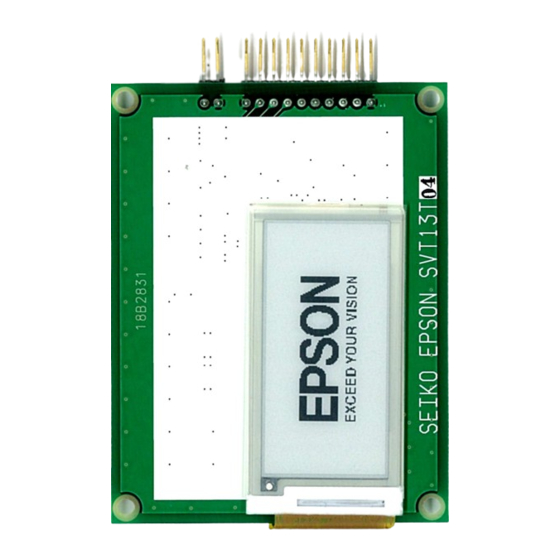
This manual describes the setup and operation of the S5U13T04P00C100 reference board. This reference board is designed as an evaluation platform for the S1D13T04 EPD Timing Controller. The S5U13T04P00C100 reference board has a host interface connector, EPD panel connector, and a 2.0 inch EPD panel. -
Page 5: Features
Page 5 Features The S5U13T04P00C100 reference board includes the following features: • Supports SPI host interface • Epson’s S1D13T04 EPD Timing Controller. • Power connector • Panel Interface connector. • 2.0 inch EPD panel. XA3A-G-001-00 S5U13T04P00C100 Evaluation Board User Manual Issue Date: 2013/03/15 Revision 1.0... -
Page 6: Setup And Configuration
S1D13T04 Panel HVDD Power CNF0 RVDD JP3/JP4 Figure 3-1 S5U13T04P00C100 Reference Board Block Diagram CNF0 is configured with jumpers JP3 and JP4 as shown in the following table. Table 3-1 CNF0 Configuration Selection CNF0 Comments Open Short H_RDY signal is all ways driven (Default) -
Page 7: Connectors
Page 7 Connectors The S5U13T04P00C100 reference board has four connectors for Host Interface, Panel Interface, Power and Reserved for Production Test (J1, J2, J3 and J4). The location of these connectors is shown in the following figure. Figure 4-1 S5U13T04P00C100 Reference Board Top View / Connector Locations... -
Page 8: J1 Panel Interface Connector
EPD VST Charge Pump C15M VCOM_PANEL EPD VCOM Capacitor J2 Power Connector Power for the S5U13T04P00C100 Evaluation Board is supplied through J2. Table 4-2 J2 Panel Interface Connector Pin No. Signal Name Description Power supply +3.0V Ground S5U13T04P00C100 Evaluation Board User Manual XA3A-G-001-00 Revision 1.0... -
Page 9: J3 Host Interface Connector
0 = Reset is active 1 = Reset is inactive Power Ground J4 Production Test Connector J4 is reserved for Production Testing and should not be used. XA3A-G-001-00 S5U13T04P00C100 Evaluation Board User Manual Issue Date: 2013/03/15 Revision 1.0 Seiko Epson Corporation... -
Page 10: Parts List
Page 10 Parts List Table 5-1 S5U13T04P00C100 Bill of Materials Item Quantity Reference Part Manufacture Description BAT54SW FH12S-40S-0.5SH(55) HIROSE Q3,Q2 2N7002 ZXMP6A13FTA DIODES Inc. Texas SN74LVC1G08IDCKR Instruments S1D13T04 EPSON P-TQFP064-1010-0.50 C11,C32 GRM21BB31A106KE18L MURATA 2012 10uF ±10% DC10V C1,C2,C3,C4,C6, C7,C8,C9,C10, C12,C30... -
Page 11: Schematic Diagram
Page 11 Schematic Diagram Figure 6-1 S5U13T04P00C100 Schematic Diagram (1 of 2) XA3A-G-001-00 S5U13T04P00C100 Evaluation Board User Manual Issue Date: 2013/03/15 Revision 1.0 Seiko Epson Corporation... - Page 12 Page 12 1uF/10V/X7R 2k/5% 2.2uF/16V/Y5V 2.2uF/16V/Y5V 2.2uF/25V/Y5V 2.2uF/25V/Y5V BAT54SW No Mount No Mount Figure 6-2 S5U13T04P00C100 Schematic Diagram (2 of 2) S5U13T04P00C100 Evaluation Board User Manual XA3A-G-001-00 Revision 1.0 Issue Date: 2013/03/15 Seiko Epson Corporation...
-
Page 13: References
Page 13 References Epson Research and Development, Inc., S1D13T04 Hardware Functional Specification, document number XA3A-A-001-xx. XA3A-G-001-00 S5U13T04P00C100 Evaluation Board User Manual Issue Date: 2013/03/15 Revision 1.0 Seiko Epson Corporation... -
Page 14: Change Record
Page 14 Change Record XA3A-G-001-00 Revision 1.0 - Issued: March 14, 2013 • Release document as rev 1.0 S5U13T04P00C100 Evaluation Board User Manual XA3A-G-001-00 Revision 1.0 Issue Date: 2013/03/15 Seiko Epson Corporation... - Page 15 EPSON HONG KONG LTD. Unit 715-723, 7/F Trade Square, 681 Cheung Sha Wan Road, Kowloon, Hong Kong. Phone: +852-2585-4600 FAX: +852-2827-4346 EPSON TAIWAN TECHNOLOGY & TRADING LTD. 14F, No. 7, Song Ren Road, Taipei 110, TAIWAN Phone: +886-2-8786-6688 FAX: +886-2-8786-6660 EPSON SINGAPORE PTE., LTD.