
Related Manuals for Epson S1D13C00


Summary of Contents for Epson S1D13C00
- Page 1 S1D13C00 S5U13C00P01C100 Customer Development Board User Manual Document Number: XB8A-G-001-01.0 Rev. 1.0...
- Page 2 2. This evaluation board/kit or development tool is intended for use by an electronics engineer and is not a consumer product. The user should use it properly and in a safe manner. Seiko Epson dose not assume any responsibility or liability of any kind of damage and/or fire coursed by the use of it. The user should cease to use it when any abnormal issue occurs even during proper and safe use.
-
Page 3: Table Of Contents
7. Host MCU Board Connections ................13 Tiva C Series EK-TM4C1294XL Launchpad ................13 STM32 Nucleo-144 development board ................. 15 8. Parts List........................17 9. S5U13C00P01C100 Schematics ................18 10. Revision History ....................... 20 Seiko Epson Corporation S5U13C00P01C100 Board User Manual (Rev. 1.0) - Page 4 Seiko Epson Corporation S5U13C00P01C100 Board User Manual (Rev. 1.0)
-
Page 5: Introduction
Launchpad evaluation board for evaluating and developing embedded EPD applications using the Epson S1D13C00 Memory Display Controller IC. It is possible to be controlled by the ST Nucleo-F746ZG or Nucleo- F767ZI board through the S5U13C00M00C100 (STM32 Nucleo-144 development board) board. - Page 6 Components * ET011TT2 panel module Serial interface Flash HULK power board interface *Booster components are part of booster circuits of ET011TT2 panel module. Figure 1.1 – S5U13C00P01C100 Block Diagram for Interface Seiko Epson Corporation S5U13C00P01C100 Board User Manual (Rev. 1.0)
-
Page 7: Connecting The Et011Tt2 Epd Panel
Connecting the ET011TT2 EPD Panel Connecting the ET011TT2 EPD Panel Figure 2 – Connecting the ET011TT2 EPD Panel Figure 2.1 – Connecting the HULK Power Board with ET011TT2 EPD Panel Seiko Epson Corporation S5U13C00P01C100 Board User Manual (Rev. 1.0) -
Page 8: Connecting To The Host Mcu Board
J4 connecting to X8, J5 connecting to X9, J6 connecting to X6, and J7 connecting to X7 respectively. Figure 3 – Connecting the S5U13C00P01C100 to the EK-TM4C1294XL Seiko Epson Corporation S5U13C00P01C100 Board User Manual (Rev. 1.0) -
Page 9: Nucleo-F746Zg Or Nucleo-F767Zi Board
First, connect the S5U13C00M00C100 adapter board to the Nucleo board. Second, connect the S5U13C00P01C100 board to the S5U13C00M00C100 adapter board. Figure 3.1 – Connecting the S5U13C00P01C100 to the Nucleo-F746ZG or Nucleo-F767ZI Seiko Epson Corporation S5U13C00P01C100 Board User Manual (Rev. 1.0) -
Page 10: Jumpers Settings
VDD_EPD supply series jumper 2-pin Installed DISPVDD source supply 1-2 = VDD_EPD 3-pin 1-2 (VDD_EPD) 2-3 = VMDL HIFCNF (host interface configuration) 1-2 = SPI/QSPI 3-pin 1-2 (SPI/QSPI) 2-3 = INDIRECT 8-BIT (not used) Seiko Epson Corporation S5U13C00P01C100 Board User Manual (Rev. 1.0) -
Page 11: Push-Buttons And Epd Panel Connectors
Push-Buttons and EPD Panel Connectors Push-Buttons and EPD Panel Connectors Figure 5 – S5U13C00P01C100 Push-Buttons and EPD Panel Connector Locations Push-Buttons Push-Button Description Reset button User button connected to P01 port pin Seiko Epson Corporation S5U13C00P01C100 Board User Manual (Rev. 1.0) -
Page 12: Header For Hulk Power Board Connection (Cn1)
EPD_BS Tied to VDD_EPD through resistor R49. EPD bus select. 3-wire serial interface is selected. EPD_RST Connected to port P03 of S1D13C00. EPD reset output from S1D13C00. EPD_BUSY Connected to port P02 of S1D13C00. EPD busy input status to S1D13C00. -
Page 13: Fpc Connector For Et011Tt2 Connection (Cn2)
The following table shows the pinout and signal connections of the 24-pin FPC (CN2): CN2 Pin Connection Description EPD_P51 Connected to P06 port of S1D13C00. FETG GDR signal of EPD panel. FETS RESE signal of EPD panel. VGL supply from EPD panel. -
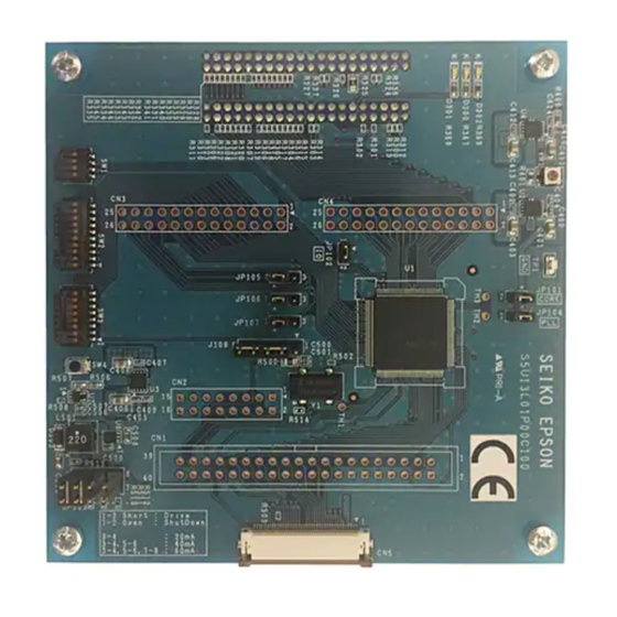
Page 14: Pre-Installed On-Board Components
Figure 6 – S5U13C00P01C100 pre-installed on-board components locations 16Mbytes QSPI Serial Flash (U2) This serial flash is directly connected to the QSPI interface of the S1D13C00. The flash can be optionally S1D13C00. accessed (read-only) through the Memory-Mapped Access area on the memory map of the... -
Page 15: Host Mcu Board Connections
The following tables show the signals of the Tiva C Series EK-TM4C1294XL Launchpad connectors which are used by the S5U13C00P01C100 Customer Development Board: EK-TM4C1294XL S5U13C00P01C100 Connector X8 Signals Signal HOST_5V HIFD0 HIFD7 HIFD6 HIFD5 HIFD1 HIFD4 HIFRD HIFIRQ EK-TM4C1294XL S5U13C00P01C100 Connector X9 Signals Signal TARGET_RST# nRST Seiko Epson Corporation S5U13C00P01C100 Board User Manual (Rev. 1.0) - Page 16 Host MCU Board Connections EK-TM4C1294XL S5U13C00P01C100 Connector X6 Signals Signal HOST_3.3V HOST_5V HIFDE HIFWR HIFD2 HIFD3 EK-TM4C1294XL S5U13C00P01C100 Connector X7 Signals Signal TARGET_RST# PA3/PQ2 PA2/PQ3 HIFCS Seiko Epson Corporation S5U13C00P01C100 Board User Manual (Rev. 1.0)
-
Page 17: Stm32 Nucleo-144 Development Board
S5U13C00P01C100 Board board Signal Signal Description J5-1 J5-2 CN10-22 Ground J5-3 J5-4 J5-5 J5-6 J5-7 J5-8 J5-9 nRST J5-10 CN8-5 Reset NRST J5-11 J5-12 J5-13 J5-14 J5-15 J5-16 J5-17 J5-18 J5-19 J5-20 Seiko Epson Corporation S5U13C00P01C100 Board User Manual (Rev. 1.0) - Page 18 Signal Signal Description J7-1 J7-2 CN10-5 Ground J7-3 J7-4 J7-5 J7-6 J7-7 J7-8 J7-9 J7-10 J7-11 J7-12 J7-13 J7-14 J7-15 HIFCS J7-16 CN9-2 Host INDIRECT8 chip-select J7-17 J7-18 J7-19 J7-20 Seiko Epson Corporation S5U13C00P01C100 Board User Manual (Rev. 1.0)
-
Page 19: Parts List
SHUNT BLACK 1x2 0.1” Omron XJ8A-0211 SW TACT SWITCH TACTILE SPST-NO 0.05A 16V Alps SKRPABE010 SW TACT SWITCH TACTILE SPST-NO 0.05A 24V Omron B3FS-1010P S1D13C00 Epson S1D13C00 TQFP13-64 Epson S1D13C00L00C000 IS25LP-128 16Mbytes SPI Flash Memory ISSI IS25LP128-JBLE MCP1700 3.3V LDO Microchip MCP1700T-3302E/TT FC-135 32.768KHz Crystal... -
Page 20: S5U13C00P01C100 Schematics
S5U13C00P01C100 Schematics S5U13C00P01C100 Schematics S5U13C00P01C100 Schematics (1 of 2) Seiko Epson Corporation S5U13C00P01C100 Board User Manual (Rev. 1.0) - Page 21 S5U13C00P01C100 Schematics S5U13C00P01C100 Schematics (2 of 2) Seiko Epson Corporation S5U13C00P01C100 Board User Manual (Rev. 1.0)
-
Page 22: Revision History
Revision History Revision History Rev. No. Date Page Category Contents 23/01/2019 Released as Rev 1.0 Seiko Epson Corporation S5U13C00P01C100 Board User Manual (Rev. 1.0) - Page 23 International Sales Operations For more information on the S1C13C00 and other Epson Display Controllers, visit the Epson Global website. https://global.epson.com/products_and_drivers/semicon/products/display_controllers/ For Sales and Technical Support, contact the Epson representative for your region. https://global.epson.com/products_and_drivers/semicon/information/support.html Document Code: XB8A-G-001-01.0 First Issue August 2018...