Table of Contents
Advertisement
Quick Links
Advertisement
Table of Contents

Related Manuals for Motorola Avigilon H4A-ETD-KIT


Summary of Contents for Motorola Avigilon H4A-ETD-KIT
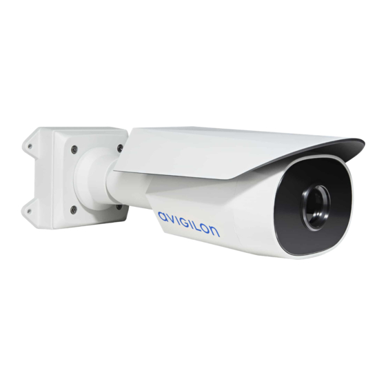
- Page 1 User Guide Avigilon H4 Thermal Elevated Temperature Detection Camera H4A-ETD-KIT...
- Page 2 Legal Notices © 2020, Avigilon Corporation. All rights reserved. AVIGILON, the AVIGILON logo, AVIGILON CONTROL CENTER, and ACC are trademarks of Avigilon Corporation. ONVIF is a trademark of Onvif, Inc. Other names or logos mentioned herein may be the trademarks of their respective owners. The absence of the symbols ™ and ®...
- Page 3 Important Safety Information This manual provides installation and operation information and precautions for the use of this device. Incorrect installation could cause an unexpected fault. Before installing this equipment read this manual carefully. Please provide this manual to the owner of the equipment for future reference. This Warning symbol indicates the presence of dangerous voltage within and outside the product enclosure that may result in a risk of electric shock, serious injury or death to persons if proper precautions are not followed.
- Page 4 Regulatory Notices This device complies with part 15 of the FCC Rules. Operation is subject to the following two conditions: (1) this device may not cause harmful interference, and (2) this device must accept any interference received, including interference that may cause undesired operation. This Class B digital apparatus complies with Canadian ICES-003.
- Page 5 The system should only be used in indoor environments with a stable ambient temperature between 18 °C and 24 °C (65 °F to 75 °F), and located in an area that is not subject to air drafts from radiator or HVAC systems.
-
Page 6: Table Of Contents
Table of Contents Overview Camera View Mounting Bracket View Tripod View Blackbody View Tilt Adjuster View Front View Configuration Panel View Side View Kit Package Contents Setting Up an Elevated Temperature Detection Station Installation Guidelines Preparing Individuals for Screening Installation Tripod Mount Installation Option Installing the Camera on the Tripod Connecting Cables... - Page 7 Configuring ACC for Elevated Temperature Detection Configuring Skin Temperature Thresholds Adding a Temperature Analytic Event Toggling Degrees Celsius and Fahrenheit Connecting to Power and External Devices Connection Status LED Indicator Maintaining the System Blackbody Maintenance Resetting to Factory Default Settings Setting the IP Address Using the ARP/Ping Method For More Information Limited Warranty and Technical Support...
-
Page 8: Overview
Overview Camera View 1. Camera mounting screws Screws for mounting the camera to the mounting bracket. 2. Tripod mount Screw for mounting the camera to the tripod or tilt adjuster. 3. Mounting hooks Hooks to attach the camera to the mounting bracket while connecting the required cables. 4. -
Page 9: Mounting Bracket View
Mounting Bracket View Note: Mounting bracket is not used when the camera is mounted on a tripod. 1. Camera mounts Points for installing the camera to the mounting bracket. 2. Mounting hook slots Points to hold the camera to the mounting bracket while connecting the required cables. 3. -
Page 10: Tripod View
Tripod View 1. Mount Mounting point for attaching to the camera or blackbody. 2. Height adjustment knobs (x3) Knobs for adjusting and locking the height of the tripod. Loosen a knob and slide the tripod to the desired height. Tighten the knobs to lock the tripod to the desired height. Tripod View... -
Page 11: Blackbody View
Blackbody View 1. Power connector Port for connecting to the included power supply. 2. Blackbody front The part of the blackbody that must be directly facing the camera. 3. Tripod mount Screw for mounting the camera to the tripod or tilt adjuster. Blackbody View... -
Page 12: Tilt Adjuster View
Tilt Adjuster View 1. Camera/Blackbody mount Mounting point for connecting to the camera or the blackbody. 2. Top tilt adjustment Move to adjust the angle of the mounted camera or blackbody. 3. Tilt lock Loosen to adjust the tilt angle. Tighten to lock to the desired angle. 4. -
Page 13: Front View
Front View 1. Configuration panel cover Covers the configuration panel. Showing the configuration panel without the tripod mount. For more information on the configuration panel, see the Configuration Panel View on the next page. Front View... -
Page 14: Configuration Panel View
Configuration Panel View 1. SD card slot Accepts an SD card for onboard storage. 2. Link LED indicator Indicates if there is an active connection in the Ethernet port. 3. Connection status LED indicator Provides information about device operation. For more information, see Connection Status LED Indicator on page 28. -
Page 15: Side View
Side View 1. Shroud An adjustable cover to help protect the lens against glare. 2. Mount arm Adjustable mount arm for positioning the camera. 3. Adjustment screws Provides a locking mechanism for the mount arm. Kit Package Contents Avigilon H4A Thermal Camera ... -
Page 16: Setting Up An Elevated Temperature Detection Station
Setting Up an Elevated Temperature Detection Station To properly setup an Elevated Temperature Detection station, many factors will need to be assessed and taken into account to obtain optimal and accurate results for the temperature detection. Review the installation guidelines and recommendations for preparing subjects for screening before installing the camera and other components. -
Page 17: Preparing Individuals For Screening
The blackbody should be positioned such that it does not get occluded when a person steps in front of the camera for screening. A recommended option is to have the blackbody positioned slightly higher than the typical individuals head and around 0.3m (1 ft) to the side of where the individuals will stand. -
Page 18: Installation
Installation Tripod Mount Installation Option For typical elevated temperature detection stations, the thermal camera will be installed on a tripod and positioned in front of the individual and the blackbody. For more information, see Installation Guidelines on page 9. Installing the Camera on the Tripod Follow the Installation Guidelines on page 9 for the recommended position and height of the camera. -
Page 19: Connecting Cables
4. Lock the tilt adjustment knob, if used, and the tripod height adjustment knobs. 5. Position tripod so the camera is directly facing the blackbody and subject. Connecting Cables 1. If there are external input or output devices that need to be connected to the camera (for example: light, LED, door contacts, relays, etc.), connect the devices to the camera's digital I/O connector cables. -
Page 20: Wall Mount Installation Option
Power over Ethernet (PoE) Class 3 — If PoE is available, the camera LEDs will turn on. External Power — Connect an external 12 V DC or 24 V AC power source through the brown and blue auxiliary power cables. Important: Be careful not to connect power to the audio input cable, doing so will permanently damage the camera. -
Page 21: (Optional) Removing The Shroud
1. Use the mounting template to drill four mounting holes into the mounting surface. 2. Drill the cable entry hole into the mounting surface then pull the required cables through the cable entry hole. 3. Fasten the mounting bracket or the junction box to the mounting surface. Note: It is recommended that silicone sealant be applied around the edge of the mounting bracket or junction box to prevent moisture from entering the mounting surface. -
Page 22: Reinstalling The Shroud
Reinstalling the Shroud 1. Use a T20 Pin-In star-shaped driver to screw on the shroud mount. 2. Align one side of the shroud to the mount. 3. Press down on the center of the shroud and flex the edges up, then lower it into place. Connecting Cables 1. -
Page 23: Mounting The Camera
Power over Ethernet (PoE) Class 3 — If PoE is available, the camera LEDs will turn on. External Power — Connect an external 12 V DC or 24 V AC power source through the brown and blue auxiliary power cables. Important: Be careful not to connect power to the audio input cable, doing so will permanently damage the camera. -
Page 24: Replacing The Configuration Panel Cover
Replacing the Configuration Panel Cover If you are mounting to a wall and do not require the tripod mount, you can replace the configuration panel with one that does not include the tripod mount. Note: This step is required for wall mounting the camera. 1. -
Page 25: Blackbody Installation
3. Tighten the adjustment screws on the mount arm to secure the camera’s position. 4. In the camera web browser interface or the Avigilon Control Center software adjust the camera’s Image and Display settings. You can change the image rotation. Blackbody Installation Follow the Installation Guidelines on page 9... - Page 26 3. Lock the tilt adjustment knob, if used, and the tripod height adjustment knobs. 4. Connect the power supply to the blackbody. Wait 5 minutes for the blackbody to power up. Verify the LED on the blackbody is on and not blinking. 5.
-
Page 27: Connecting To The Camera
Connecting to the Camera Initializing a Camera Username and Password Cameras manufactured after January 1, 2020, do not have a default username or password and will be in a factory default state. Important: You must create a user with administrator privileges before the camera is operational. The first user can be created using any of the following methods: ... -
Page 28: (Optional) Configuring Sd Card Storage
Note: If the device cannot obtain an IP address from a DHCP server, it will use Zero Configuration Networking (Zeroconf) to choose an IP address. When set using Zeroconf, the IP address is in the 169.254.0.0/16 subnet. The IP address settings can be changed using one of the following methods: ... -
Page 29: Initial Camera Setup And Configuration
Initial Camera Setup and Configuration Setting the Blackbody Region of Interest Before setting the blackbody region of interest, make sure that the camera and blackbody are installed and positioned correctly to detect temperatures. For more information, see Installation Guidelines on page 9. - Page 30 1. Launch and login to your ACC Client. Open a live view for the elevated temperature detection camera. 2. Manually take the body temperature of a test subject using an clinical thermometer or other trusted and accurate temperature device. Make a note of this temperature. It is recommended that you take more than one measurement to ensure a proper reading.
-
Page 31: Configuring Acc For Elevated Temperature Detection
Configuring ACC for Elevated Temperature Detection ACC software version 7.10 or later is required for use with the H4 Thermal Elevated Temperature Detection camera. In an ACC Client, you can configure the skin temperature threshold for subjects with elevated and low temperatures. -
Page 32: Adding A Temperature Analytic Event
Adding a Temperature Analytic Event The temperature events can be used to set up notifications or rules. 1. In the New Task menu , click Site Setup. 2. Select a camera, then click Analytic Events 3. Click Add. 4. Enter a name. This should be unique throughout the ACC site. 5. -
Page 33: Connecting To Power And External Devices
Connecting to Power and External Devices Important: Be careful not to connect auxiliary power to the audio input wire or the camera will be damaged. Although both the audio input wire and auxiliary power wire are brown, the auxiliary power wire is distinguished by its thicker wire gauge and AUX PWR label. If PoE is not available, the camera may be powered through the auxiliary power cable using either 12 V DC or 24 V AC. - Page 34 3. Green — Audio Output (line level) 4. Grey — Ground 5. Red — Digital Input 6. Pink — Digital Output 7. Purple — Reserved Wire, do not connect. 8. White — Reserved Wire, do not connect. * — Relay ...
-
Page 35: Connection Status Led Indicator
Connection Status LED Indicator Once connected to the network, the Connection Status LED indicator will display the progress in connecting to the Network Video Management software. The following table describes what the LED indicator shows: Connection State Connection Status Description LED Indicator Obtaining One short flash... -
Page 36: Maintaining The System
Maintaining the System Blackbody Maintenance The blackbody device requires manufacturer calibration and testing every 2 years to have the device's certification maintained. Please contact Avigilon to arrange sending your device for calibration after 2 years. Warranty service and technical support can be obtained by contacting Avigilon Technical Support: avigilon.com/contact. -
Page 37: Resetting To Factory Default Settings
Resetting to Factory Default Settings If the device no longer functions as expected, you can choose to reset the device to its factory default settings. Use the firmware revert button to reset the device. The firmware revert button is shown in the following diagram: For models that feature an SD card slot, resetting the camera will not affect video that has been recorded to the SD card. -
Page 38: Setting The Ip Address Using The Arp/Ping Method
Setting the IP Address Using the ARP/Ping Method Complete the following steps to configure the camera to use a specific IP address: Note: The ARP/Ping Method will not work if the Disable setting static IP address through ARP/Ping method checkbox is selected in the camera's web browser interface. For more information, see the Avigilon High Definition H4 and H5 IP Camera Web Interface User Guide. -
Page 39: For More Information
For More Information Additional information about setting up and using the device is available in the following guides: Avigilon Control Center Client User Guide Web Interface User Guide — Avigilon High Definition H4 and H5 IP Cameras Avigilon USB Wi-Fi Adapter System User Guide ... -
Page 40: Limited Warranty And Technical Support
Limited Warranty and Technical Support Avigilon warranty terms for this product are provided at avigilon.com/warranty. Warranty service and technical support can be obtained by contacting Avigilon Technical Support: avigilon.com/contact. Limited Warranty and Technical Support...