
Related Manuals for Motorola Avigilon H4 SL Series


Summary of Contents for Motorola Avigilon H4 SL Series
- Page 1 Installation Guide Avigilon H4 SL Bullet Camera Models: 1.3C-H4SL-BO1-IR, 2.0C-H4SL-BO1-IR and 3.0C-H4SL-BO1-IR...
- Page 2 Legal Notices © 2016 - 2019, Avigilon Corporation. All rights reserved. AVIGILON, the AVIGILON logo, AVIGILON CONTROL CENTER, and ACC are trademarks of Avigilon Corporation. ONVIF is a trademark of Onvif, Inc. Other names or logos mentioned herein may be the trademarks of their respective owners. The absence of the symbols ™...
- Page 3 Important Safety Information This manual provides installation and operation information and precautions for the use of this device. Incorrect installation could cause an unexpected fault. Before installing this equipment read this manual carefully. Please provide this manual to the owner of the equipment for future reference. This Warning symbol indicates the presence of dangerous voltage within and outside the product enclosure that may result in a risk of electric shock, serious injury or death to persons if proper precautions are not followed.
- Page 4 Regulatory Notices This device complies with part 15 of the FCC Rules. Operation is subject to the following two conditions: (1) this device may not cause harmful interference, and (2) this device must accept any interference received, including interference that may cause undesired operation. This Class B digital apparatus complies with Canadian ICES-003.
-
Page 5: Table Of Contents
Table of Contents Overview Mounting Bracket View Rear View Front View Configuration Panel View Side View Installation Camera Package Contents Installation Steps Mounting the Bullet Camera Removing the Configuration Panel Cover (Optional) Using the USB Wi-Fi Adapter Assigning an IP Address Accessing the Live Video Stream Aiming the Camera (Optional) Configuring microSD Card Storage... -
Page 6: Overview
Overview Mounting Bracket View 1. Camera mounts Points for installing the camera to the mounting bracket. 2. Mounting hook slots Points to hold the camera to the mounting bracket while connecting the required cables. 3. Mounting holes Holes for securing the mounting bracket to the mounting surface. Overview... -
Page 7: Rear View
Rear View 1. Ethernet port Accepts power and Ethernet connection to the network. The camera can only be powered by Power over Ethernet (PoE). Server communication and image data transmission also occur over this connection. 2. Serial number tag Device information, product serial number and part number label. 3. -
Page 8: Front View
Front View 1. IR illuminator Provides scene illumination in the IR spectrum. 2. Configuration panel cover Covers the configuration panel. Front View... -
Page 9: Configuration Panel View
Configuration Panel View 1. microSD card slot Accepts a microSD card for onboard storage. 2. Micro USB port Accepts a micro USB to USB adapter. Only required when using the Avigilon USB Wi-Fi Adapter. 3. Link LED indicator Indicates if there is an active connection in the Ethernet port. 4. -
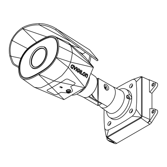
Page 10: Side View
Side View 1. Sun shroud An adjustable cover to help protect the lens against glare from the sun. 2. Mount arm Adjustable mount arm for positioning the camera. 3. Adjustment screws Provides a locking mechanism for the mount arm. Side View... -
Page 11: Installation
Installation Camera Package Contents Avigilon H4 SL Bullet Camera Mounting template sticker 4 screws and anchors for solid walls Installation Steps Complete the following sections to install the device. Mounting the Bullet Camera If the cables for the camera will not be provided from inside the mounting surface, install the junction box first (H4-BO-JBOX). - Page 12 3. Fasten the mounting bracket to the mounting surface or junction box. 4. Insert the mounting hooks on the rear of the camera into the mounting hook slots on the mounting bracket, then let the camera hang. Mounting the Bullet Camera...
- Page 13 5. Install the protective cable boot. You may choose to skip this step if you are using the optional junction box. a. Remove the protective cable boot that is preinstalled over the Ethernet port, then thread one end of the Ethernet cable through it. Ensure the orientation of the cable and boot matches the one shown in the image.
- Page 14 8. Raise the camera until it covers the mounting bracket. 9. Use the camera mounting screws to fasten the camera to the bracket. Mounting the Bullet Camera...
-
Page 15: Removing The Configuration Panel Cover
Removing the Configuration Panel Cover 1. Use a T20 Pin-In Torx driver to unscrew the configuration panel cover. 2. Remove the cover from the configuration panel. (Optional) Using the USB Wi-Fi Adapter If you have a USB Wi-Fi Adapter (H4-AC-WIFI), attach it to the camera's micro USB port to access the camera's mobile web interface. -
Page 16: Accessing The Live Video Stream
software). ARP/Ping method. For more information, see Setting the IP Address Using the ARP/Ping Method on page 16. NOTE: The default device username is administrator with no password. Accessing the Live Video Stream Live video stream can be viewed using one of the following methods: The mobile web interface using the USB Wifi Adapter. -
Page 17: (Optional) Configuring Microsd Card Storage
3. Loosen the adjustment screw on the camera to turn the camera body. 4. If the camera is turned sideways to look vertically at a scene, you can remove the sun shroud then re- install it to cover the camera's new angle of view. (Optional) Configuring microSD Card Storage To use the camera's SD card storage feature, you must insert a microSD card into the card slot. -
Page 18: Configuring The Camera
Configuring the Camera Once installed, use one of the following methods to configure the camera: If you have the USB Wifi Adapter, you can access the mobile web interface to configure the camera. For more information, see Avigilon USB Wi-Fi Adapter System User Guide. If you have installed multiple cameras, you can use the Avigilon Camera Configuration Tool to configure common settings. -
Page 19: Connection Status Led Indicator
Connection Status LED Indicator Once connected to the network, the Connection Status LED indicator will display the progress in connecting to the Network Video Management software. The following table describes what the LED indicator shows: Connection State Connection Status Description LED Indicator Obtaining One short flash... -
Page 20: Resetting To Factory Default Settings
Resetting to Factory Default Settings If the device no longer functions as expected, you can choose to reset the device to its factory default settings. Use the firmware revert button to reset the device. The firmware revert button is shown in the following diagram: Figure 1: The firmware revert button in the Configuration Panel. -
Page 21: Setting The Ip Address Using The Arp/Ping Method
Setting the IP Address Using the ARP/Ping Method Complete the following steps to configure the camera to use a specific IP address: NOTE: The ARP/Ping Method will not work if the Disable setting static IP address through ARP/Ping method check box is selected in the camera's web browser interface. For more information, see the Web Interface User Guide —... -
Page 22: Specifications
Specifications Camera Lens 3-9 mm, motorized, varifocal USB Port USB 2.0 SD Storage microSD/microSDHC/microSDXC slot – minimum class 6; class 10/UHS-1 or better recommended Network Network 100Base-TX Cabling Type CAT5 Connector RJ-45 ONVIF ONVIF® compliance version 1.02, 2.00, Profile S (www.onvif.org) Device SNMP v2c Management... - Page 23 Consumption Power Source PoE: IEEE802.3af Class 3 compliant RTC Backup 3V manganese lithium Battery Environmental Operating -30 °C to +60 °C (-22°F to 140 °F) Temperature Storage -10 °C to +70 °C (14 °F to 158 °F) Temperature Humidity 0-95% non-condensing Certifications Certifications ROHS...
-
Page 24: Limited Warranty And Technical Support
Limited Warranty and Technical Support Avigilon warranty terms for this product are provided at avigilon.com/warranty. Warranty service and technical support can be obtained by contacting Avigilon Technical Support: avigilon.com/contact-us/. Limited Warranty and Technical Support...