
Related Manuals for Motorola Avigilon H4SL-MT-NPTA


Summary of Contents for Motorola Avigilon H4SL-MT-NPTA
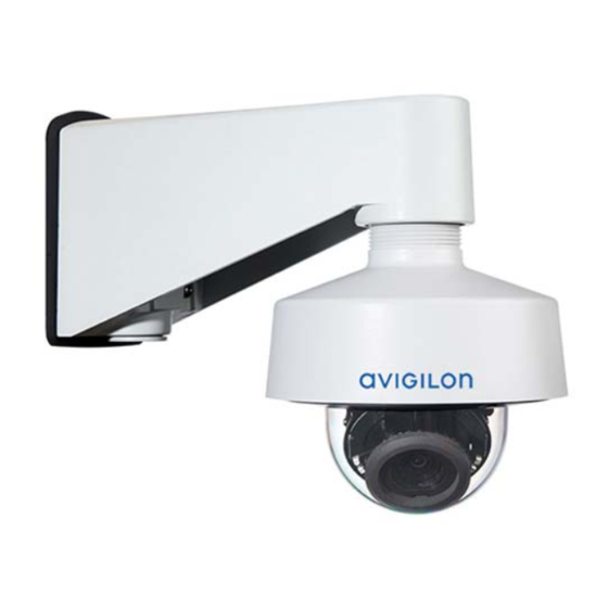
- Page 1 Installation Guide Avigilon H4 SL Dome Camera Models with Pendant Mount Adapters: H4SL-D/H4SL-DO plus H4SL-MT-NPTA and CM-MT-WALL...
- Page 2 Important Safety Information This manual provides installation and operation information and precautions for the use of this device. Incorrect installation could cause an unexpected fault. Before installing this equipment read this manual carefully. Please provide this manual to the owner of the equipment for future reference. This Warning symbol indicates the presence of dangerous voltage within and outside the product enclosure that may result in a risk of electric shock, serious injury or death to persons if proper precautions are not followed.
- Page 3 Regulatory Notices This device complies with part 15 of the FCC Rules. Operation is subject to the following two conditions: (1) this device may not cause harmful interference, and (2) this device must accept any interference received, including interference that may cause undesired operation. This Class B digital apparatus complies with Canadian ICES-003.
- Page 4 Legal Notices © 2016 - 2020, Avigilon Corporation. All rights reserved. AVIGILON, the AVIGILON logo, AVIGILON CONTROL CENTER, and ACC are trademarks of Avigilon Corporation. ONVIF is a trademark of Onvif, Inc. Other names or logos mentioned herein may be the trademarks of their respective owners. The absence of the symbols ™...
-
Page 5: Table Of Contents
Table of Contents Overview Cover View NPT Adapter View Pendant Wall Mount Bracket View Pendant Wall Mount View Camera Base Bottom View Camera Base Front View Camera Base Rear View Installation Required Tools and Materials Package Content Installation Steps Removing the Dome Cover Inserting Cables through the Sealing Grommet Mounting the Dome Camera to a Pipe (Optional) Mounting the Dome Camera to the Pendant Wall Mount... -
Page 6: Overview
Overview Cover View 1. NPT adapter Used to mount the dome camera to NPT pipes. 2. Pendant wall mount (optional) Used with the NPT adapter to mount the dome camera to a wall in pendant installations. 3. Tamper resistant screws Star-shaped captive screws to fix the dome cover to the base. -
Page 7: Npt Adapter View
NPT Adapter View 1. Camera housing clips Snaps to hold camera module during installation. 2. Lanyard Connects to the lanyard anchor on the camera base. 3. 1-1/2” NPT thread mount Standard male 1-1/2” NPT thread mount for mounting the dome camera to a pole or bracket. NPT Adapter View... -
Page 8: Pendant Wall Mount Bracket View
Pendant Wall Mount Bracket View 1. Bracket mounting holes Points for mounting the pendant wall mount bracket to a mounting surface. 2. Mounting tabs Tabs for placing the pendant wall mount onto the bracket. 3. Mounting points Points for securing the pendant wall mount to the mounting bracket. Pendant Wall Mount Bracket View... -
Page 9: Pendant Wall Mount View
Pendant Wall Mount View 1. 1-1/2” NPS thread mount Female NPS thread mount for pendant camera installations. 2. Pendant wall mount screws Screws for securing the pendant wall mount to the mounting bracket. 3. NPT pipe entry hole A 3/4” NPT threaded hole for NPT pipe conduits. Pendant Wall Mount View... -
Page 10: Camera Base Bottom View
Camera Base Bottom View 1. Cable entry hole An entry hole for the cables required for camera operation. 2. Lanyard anchor The safety lanyard attaches to the anchor to prevent the camera from falling during installation. 3. Vent Vent to allow moisture vapor to escape the sealed housing and equalize pressure. Only available on H4SL-DO models. -
Page 11: Camera Base Front View
Camera Base Front View 1. IR illuminator Provides scene illumination in the IR spectrum. Only available on -IR models. 2. Ethernet port Accepts power and Ethernet connection to the network. The camera can only be powered by Power over Ethernet (PoE). Server communication and image data transmission also occur over this connection. -
Page 12: Camera Base Rear View
Camera Base Rear View Displayed IR illuminators only available on -IR models. 1. Azimuth control Provides control of the image angle. 2. Tilt lock thumb screw Provides a locking mechanism for the image tilt adjustment. 3. Pan lock latch Provides a locking mechanism for the image pan adjustment. 4. -
Page 13: Installation
Installation Required Tools and Materials The following tools are required to complete the installation but are not included in the package: No. 2 Phillips screwdriver — for attaching the pendant wall mount bracket to the mounting surface. Package Content Ensure the dome camera package contains the following: Avigilon H4 SL Dome Camera (Indoor model —... -
Page 14: Installation Steps
Pendant wall mount Mounting template sticker T20 Pin-In star-shaped driver 4 concrete anchors (#8-10) 4 screws (#8 x 1.25) RJ-45 grommet piercing cap Teflon sealing tape Installation Steps Complete the following sections to install the device. Removing the Dome Cover Note: Be careful not to scratch or touch the dome bubble. -
Page 15: Mounting The Dome Camera To A Pipe
1. Remove the sealing grommet from the camera base. 2. Push the Ethernet cable through the grommet. If you are installing the indoor model (H4SL-D), you should be able to simply push the cable, crimped or uncrimped, through the grommet by hand. If you are installing the outdoor model (H4SL-DO), use one of the following methods: a. -
Page 16: (Optional) Mounting The Dome Camera To The Pendant Wall Mount
a. NPT conduit pipe b. 1-1/2" NPT female to female pipe adapter c. Lock nut d. NPT adapter (Optional) Mounting the Dome Camera to the Pendant Wall Mount If the dome camera will be using the pendant wall mount, you will need to install the NPT adapter as well. 1. - Page 17 3. Fasten the pendant wall mount bracket to the mounting surface. 4. Insert the pendant wall mount over the bracket mounting tabs. 5. Pull the required cables through the preferred cable entry hole on the pendant wall mount. If you are using the pipe entry hole, pull the cables through the pipe conduit then the wall mount.
- Page 18 6. Tighten the wall mount screws to secure the wall mount to the bracket. Use the T20 star-shaped key provided in the camera package. (Optional) Mounting the Dome Camera to the Pendant Wall Mount...
-
Page 19: Installing The Camera Base To The Mounting Adapter
7. Loosely thread the lock nut onto the NPT adapter, then secure the NPT adapter into the pendant wall mount. 8. Carefully tighten the lock nut until the NPT adapter is secured to the wall mount. Installing the Camera Base to the Mounting Adapter After you install the mounting adapter, mount the camera base to the adapter. - Page 20 1. Attach the lanyard on the mounting adapter to the anchor on the camera base. 2. Pull the required Ethernet cable through the cable entry hole on the camera base. 3. Install the grommet into the cable entry hole on the camera base. Make sure the grommet flange is securely seated on the inside and outside of the cable entry hole.
-
Page 21: (Optional) Using The Usb Wi-Fi Adapter
5. Align the orange arrow on the camera base to the orange arrow on the mounting adapter, then press the camera base into the mounting adapter. The camera base clicks into place and is held securely. (Optional) Using the USB Wi-Fi Adapter If you have a USB Wi-Fi Adapter (H4-AC-WIFI), attach it to the camera's micro USB port to access the camera's mobile web interface. -
Page 22: Accessing The Live Video Stream
The mobile web interface using the USB Wifi Adapter. For more information, see (Optional) Using the USB Wi-Fi Adapter on the previous page. Device's web browser interface: http://<camera IP address>/. Network Video Management software application (for example, the Avigilon Control Center™ software). - Page 23 2. Loosen the tilt lock thumb screw to tilt the lens. 3. Adjust the tilt angle of the camera as needed. Aiming the Dome Camera...
-
Page 24: (Optional) Configuring Microsd Card Storage
Avigilon recommends that you adjust the tilt angle within the range indicated by the markings for best results. Tilting the camera past these markings is possible, but may result in infrared reflections beyond an acceptable level. 4. Lock the pan lock latch and tighten the tilt lock screw to secure the dome camera’s position. 5. -
Page 25: Installing The Dome Cover
Installing the Dome Cover 1. Attach the dome cover to the base by tightening the screws with the Torx driver. 2. Remove the protective cover on the outside of the dome bubble. Zooming and Focusing the Dome Camera Ensure this procedure is performed after the dome cover is installed so you can accommodate for the focus shift caused by the dome bubble. -
Page 26: For More Information
If the camera is connected to the Avigilon Control Center system, you can use the client software to configure the camera. For more information, see the Avigilon Control Center Client User Guide. If the camera is connected to a third-party network management system, you can configure the camera's specialty features in the camera's web browser interface. -
Page 27: Connection Status Led Indicator
Connection Status LED Indicator Once connected to the network, the Connection Status LED indicator will display the progress in connecting to the Network Video Management software. The following table describes what the LED indicator shows: Connection State Connection Status Description LED Indicator Obtaining One short flash... -
Page 28: Removing The Dome Camera From The Mounting Adapter
Removing the Dome Camera from the Mounting Adapter 1. Loosen the star-shaped screws and remove the dome cover. 2. Locate the small orange arrows that point at the camera housing clips. 3. Insert a flat head screwdriver or grommet piercing cap against one of the camera housing clips. 4. -
Page 29: Resetting To Factory Default Settings
Resetting to Factory Default Settings If the device no longer functions as expected, you can choose to reset the device to its factory default settings. Use the firmware revert button to reset the device. The firmware revert button is shown in the following diagram: 1. -
Page 30: Setting The Ip Address Using The Arp/Ping Method
Setting the IP Address Using the ARP/Ping Method Complete the following steps to configure the camera to use a specific IP address: Note: The ARP/Ping Method will not work if the Disable setting static IP address through ARP/Ping method check box is selected in the camera's web browser interface. For more information, see the Avigilon High Definition H4 and H5 IP Camera Web Interface User Guide. -
Page 31: Specifications
Specifications Camera Lens 3-9 mm, motorized, varifocal USB Port USB 2.0 SD Storage microSD/microSDHC/microSDXC slot – minimum class 6; class 10/UHS-1 or better recommended Network Network 100Base-TX Cabling Type CAT5 Connector RJ-45 ONVIF® compliance version 1.02, 2.00, Profile S (www.onvif.org) Device SNMP v2c Management SNMP v3... - Page 32 Housing Pendant mount H4SL-D — tamper resistant H4SL-DO — vandal resistant Finish Polycarbonate — Fog coat, cool grey Aluminum — Powder coat, cool grey Adjustment Range 360° pan, 30° – 95° tilt, ±180° azimuth Electrical Power H4SL-D — 4 W max Consumption H4SL-DO —...
- Page 33 Emissions EN 55022 Class B EN 55032 IC ICES-003 Class B EN 61000-6-3 EN 61000-3-2 EN 61000-3-3 KN 32 Electromagnetic EN 55024 Immunity EN 61000-6-1 EN 50130-4 KN 35 Specifications...
-
Page 34: Limited Warranty And Technical Support
Limited Warranty and Technical Support Avigilon warranty terms for this product are provided at avigilon.com/warranty. Warranty service and technical support can be obtained by contacting Avigilon Technical Support: avigilon.com/contact-us/. Limited Warranty and Technical Support...