ABB Terra DC wallbox Installation Manual
Hide thumbs
Also See for Terra DC wallbox:
- Installation manual (44 pages) ,
- User's operation manual (20 pages) ,
- Quick start manual (2 pages)
Table of Contents
Advertisement
Quick Links
Advertisement
Table of Contents

Related Manuals for ABB Terra DC wallbox


Summary of Contents for ABB Terra DC wallbox
- Page 1 — MAN U A L Terra DC wallbox Installation Manual...
- Page 2 This document contains information about one or more ABB products and may include a descrip- tion of or a reference to one or more standards that may be generally relevant to the ABB products. The presence of any such description of a standard or reference to a standard is not a representa- tion that all of the ABB products referenced in this document support all of the features of the de- scribed or referenced standard.
-
Page 3: Table Of Contents
Contents 1 Introduction ..............................6 Preface ............................... 6 Intended document users ........................6 Similarities and differences between Terra DC Wallbox EU and NAM ........6 Terra DC Wallbox version description ....................7 Signs ................................7 1.5.1 Owner responsibilities ......................8 1.5.2... - Page 4 9 Contact information ..........................37 10 Appendix A – Mounting points ........................38 10.1 Terra DC Wallbox Charger wall mounting ..................38 11 Appendix B - Disposal instruction ......................39 11.1 Directive on Waste Electrical and Electronic Equipment (WEEE – 2012/19/EU) ....39...
- Page 5 Grid provider Company responsible for the transportation and distribution of electricity. Human Machine Interface; the display/screen on the charger. ABB Network Operating Centre; remotely checks the correct functioning of the charger. Owner The legal owner of the charger. OCPP Open Charge Point Protocol. Open standard for communication with charge stations.
-
Page 6: Introduction
This guide describes and highlights the physical installation of the Terra DC Wallbox at its location. The Terra DC Wallbox Charging Stations are easy to install DC fast chargers for electric vehicles. Fast chargers are electrical installations with high electric currents. Therefore, the installation must be planned carefully, and must be done by certified personnel only (according to local standards). -
Page 7: Terra Dc Wallbox Version Description
T ERRA D C WA LLBO X On the inside of the system there are some differences. The Terra DC Wallbox EU version has a AC input board provided with contact blocks for main connection that are de- signed to be connected with a three phase + neutral power grid. On the other hand, the NAM version has a different AC input board designed to be connected with a phase to phase power grid. -
Page 8: Owner Responsibilities
ABB could void the owner’s authority to operate the equipment and ABB’s war- ranty policy Neither ABB nor its affiliates shall be liable to the purchaser of this product or • third parties for damages, losses, costs or expenses incurred by purchaser or... -
Page 9: Tilting And Handling
6. Always connect the Protective Earth (PE) first, before con- necting the neutral (N) and Phase (P) wiring. 7. Correctly fixate the enclosure of the Terra DC Wallbox af- ter installation or service operations. 2 2 -O CT -19... -
Page 10: Environment And Disposal Of Waste
T ERRA D C WA LLBO X 1.6 Environment and disposal of waste NOTICE Always observe the local rules and regulations with respect to processing (non-reusable) parts of the Terra DC Wallbox. 2 Description of the product Overview of the system 2.1.1... -
Page 11: Outside View
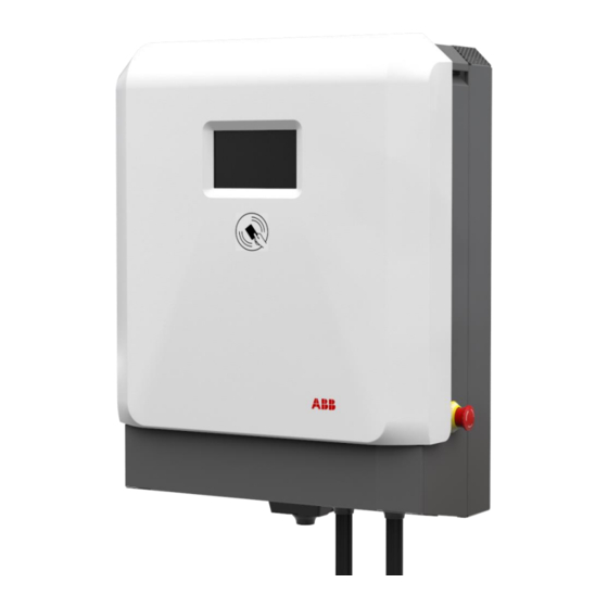
T ERRA D C WA LLBO X 2.1.2 Outside view Display / HMI Emergency button RFID card reader AC input cable Charging outlets DC Air inlet Air outlet Gunholder (optional) 2 2 -O CT -19 1 1/ 40... -
Page 12: Inside View
2.2.1 Required space for placing and maintaining the Terra DC Wallbox The Terra DC Wallbox requires a minimum space of 900 x 1200 mm. This space is calcu- lated as follows: - Size Charger W x D x H: 304.5 x 512 x 770 mm. -
Page 13: Ventilation And Airflow Of The Terra Dc Wallbox
T ERRA D C WA LLBO X 2.2.2 Ventilation and airflow of the Terra DC Wallbox The Terra DC Wallbox has an air inlet on the bottom side and outlet on the top side. NOTICE Free air flow If necessary, take precautions to prevent snow or objects from blocking the in- and outlets. -
Page 14: Electrical Engineering
As all variant have an internal a DC fault current monitoring function, a DC fault cur- rent over 6 mA does NOT occur on the AC-input side of the TERRA DC WALLBOX, and thus an upstream RCD of type B is not required, nevertheless local regulation could require a RCD of Type B independent of internal DC fault current limitation NOTE. -
Page 15: Conductor And Cable Diameter
T ERRA D C WA LLBO X RCD/GFCI that has proven to be able to withstand these short current peaks (high im- munity). CAUTION Responsibility to comply with local regulations The installation company is responsibly to design and install the electrical installation according the local regulations. 2.3.2 Conductor and cable diameter The diameter of the electrical conductor of the ground cables depends on the length,... -
Page 16: Site Design
Cable reach The charging cables of the Terra DC Wallbox charger can reach from 3.5 to 7 meters long. The DC cables leave the charger on both right and left sides. The cables and the con- nectors mounted on the cables are different for each charging standard and make them more or less flexible to reach out. - Page 17 T ERRA D C WA LLBO X This makes some positions of the charger with respect to the parking space more fa- vorable than others. Please keep this in mind when designing a site. Some possible situ- ations are shown below: 2 2 -O CT -19 1 7/ 40...
-
Page 18: Site Construction
About construction The construction phase includes all work required to prepare the location and make it ready for the placement and connection of the Terra DC Wallbox charger. The construc- tion phase can start when: The wall preparation work is done. -
Page 19: Internet Connection
4 Mb/s. • Recommended availability: 99,9%. • The connection must be available for the ABB service engineer and the NOC (Network Operation Center). • Please contact ABB for a specific configuration. In case the separate internet connection is not used, please assure the cable entry hole is closed, to assure the IP54 grade of the cabinet, and prevent insects and small animals to enter the cabinet. -
Page 20: Receiving, Placing And Connecting
Receiving the Wallbox The product is delivered by a transport company to a warehouse where it will be handed over. Transporting the Terra DC Wallbox to its final location (last mile service) is not standard included in the order. NOTICE The delivery truck unloads the pallet carrying the Terra DC Wallbox. -
Page 21: Unpacking Wallox, Mounting Preparations
Unpacking Wallbox, mounting preparations 5.2.1 Unpacking The packaging of the Terra DC Wallbox can be removed without the use of tools and be careful because it could pollute of the environment. 1. Remove the plastic protection profiles. 2. Remove the Bottom Grid and the Lower Frontal Cover 3. -
Page 22: Mounting Preparations
Bottom grid cover Move cabinet to position 5.3.1 Options The only option to move the Terra DC Wallbox from the delivery truck to the location is through a forklift truck. DANGER Hazardous voltage Make sure the main switch of the power supply group for the product is set to the OFF position. -
Page 23: Mounting The Terra Dc Wallbox
5.4.1 Mounting the Terra DC Wallbox NOTICE The number of people that can lift a Terra DC Wallbox during installation is a minimum of two. In general, local regulations should be followed as the maximum weight to be lifted may vary country by country. - Page 24 T ERRA D C WA LLBO X 6. Tighten the two M5 bolts on the lower side of the unit. Pay attention to the internal fan power supply cable. 7. Let the auxiliary power supply cable pass through the central gland and tight it. 2 2 -O CT -19 2 4/ 40...
- Page 25 T ERRA D C WA LLBO X 8. AFTER the cable connection (refer to para 5.4.2 and 5.5), take the bottom grid and put it on the lower side of the unit and fix it by tightening two screws as shown in the following picture.
-
Page 26: Install Cable Gland(S)
T ERRA D C WA LLBO X 11. Put the central cover on the unit and fix it tightening two screws located on the left and right side of the cover and (see detail on the following picture). Center the bot- tom pins and then rotate the cover and tight the 2 lateral screws. - Page 27 T ERRA D C WA LLBO X 1. Slide the cable inside the grommets, ensure at least 10mm of cable external jacket inside the box (see notes at the end of this §, Before sliding the cable inside the grom- met).
-
Page 28: Connect Cables
T ERRA D C WA LLBO X In case the separate internet connection is not used, please assure the cable entry hole is closed, to assure the IP54 grade of the cabinet, and prevent insects and small animals to enter the cabinet. NOTE 1: a ferrite core is provided with the wallbox (plastic bag within the package) and needs to be installed in commissioning phase. -
Page 29: Connect Power Cable
For safety, it is recommended to make the PE wire longer than the phase wires. This makes sure that the PE wire stays connected as longest, if the Terra DC Wallbox is moved by a collision. 2. Use wire stripper pliers to remove 20 mm of the insulation from the end of the PE wire and attach the cable lugs. -
Page 30: Connect Network Cable
5.5.3 Connect network cable WARNING Leave the main switch switched off. The Terra DC Wallbox is not ready for use yet. Please contact the ABB Service de- partment at least one week in advance to make an appoint- ment for commissioning. -
Page 31: Commissioning
6 Commissioning Commissioning preparation Commissioning is the last phase necessary to get the Terra DC Wallbox operational. The purpose is to check the safe functioning of the charger for its operational purpose. A certified service engineer from the ABB Service department or a trained engineer by ABB is required to perform the commissioning. - Page 32 • Change Deliver status to <SAT>. After completing the Site Acceptance Test, ABB’s Network Operation Center will be trig- gered to perform a final check on the connection and configuration of the charger. Upon approval the charger will be operational and initialized for use.
-
Page 33: Cleaning Of The Cabinet
7 Cleaning of the cabinet Cleaning of the cabinet The Terra DC Wallbox Charger is powder coated. This coating must be kept in good con- dition. Clean the Terra DC Wallbox Charger three times a year in the following way: •... -
Page 34: Technical Data
T ERRA D C WA LLBO X 8 Technical Data Electrical data Input 3 phase, 400 V AC: PE, N, L1, L2, L3 (EU) Supply voltage 1 phase / 2 phases, 208 V AC/240 V AC: PE, L1, L2 (NAM) 3 phase, 277Y/480Δ... - Page 35 T ERRA D C WA LLBO X RFID system FeliCa™1, NFC reader mode GSM / CDMA modem Network connection 10/100 Base-T Ethernet 2 2 -O CT -19 3 5/ 40...
-
Page 36: Mechanical Data
T ERRA D C WA LLBO X Mechanical data Mechanical data Dimensions (H x W x D) 770 mm x 585 mm x 300 mm Weight 70 kg Volume 0,135 m Dimensions including packaging (H X W x D) 650 mm x 1200 mm x 800 mm Weight including packaging 80 kg Mechanical impact protection... -
Page 37: Contact Information
In case they cannot solve the problem, they will contact the second line Service organization. ABB in your country Please contact ABB in your country for sales, delivery and service information. ABB EV Infrastructure global ABB EV Infrastructure Address... -
Page 38: Appendix A - Mounting Points
T ERRA D C WA LLBO X Appendix A – Mounting points 10.1 Terra DC Wallbox Charger wall mounting 2 2 -O CT -19 38 /40... -
Page 39: Appendix B - Disposal Instruction
T ERRA D C WA LLBO X Appendix B - Disposal instruction 11.1 Directive on Waste Electrical and Electronic Equipment (WEEE – 2012/19/EU) 2 2 -O CT -19 39/ 40... - Page 40 T ERRA D C WA LLBO X 2 2 -O CT -19 40/ 40...