Table of Contents
Advertisement
Advertisement
Table of Contents

Related Manuals for Toshiba BMS-IFBN640TLE


Summary of Contents for Toshiba BMS-IFBN640TLE
- Page 1 Installation Manual BN interface Model name: BMS-IFBN640TLE English...
-
Page 2: Table Of Contents
BN interface Installation Manual Contents Precautions for safety ........... . 3 Introduction. -
Page 3: Precautions For Safety
BN interface Installation Manual Precautions for safety The following instructions must be observed. • Carefully read these "Precautions for Safety" before installation, and perform installation work safely. • These precautions contain important information regarding safety. • After installation work, carry out an operation trial to confirm that there are no problems, and explain to the customer how to operate and maintain the system. -
Page 4: Introduction
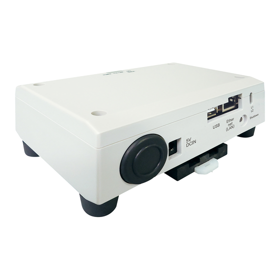
BN interface Installation Manual Introduction Overview The BN interface refers to equipment used for controlling Building Management Systems (Procured locally) and air conditioners (TCC-LINK compatible models) through communications via a network to enable centralized control. Included Items Component Q'ty Remarks BN interface equipment... - Page 5 BN interface Installation Manual (Power adapter) REQUIREMENT Power cable is not supplied for the BN Interface. Insert a two core power cord applicable to the standard of the country you use. Component Names Name Function 5V DCIN Connect the power adapter (For service) Ethernet (LAN) Connect to the Building Management System...
-
Page 6: Installation
BN interface Installation Manual Installation REQUIREMENT Do not install the unit in any of the following places. • Humid or wet place • Dusty place • Place exposed to direct sunlight • Place where there is a TV set or radio within one meter •... - Page 7 BN interface Installation Manual Installation Space and Maintenance Space A side space for connecting through cable inlets and an upper space for maintenance must be reserved before installation. The other sides can be adjacent to surrounding objects.
-
Page 8: Power And Signal Line Connections
BN interface Installation Manual Power and signal line connections Cables Use the following cable for signal line connections. (Procured locally) Line Description Type 2-core shielded wires For TCC-LINK Wire size 1.25 mm , 1000 m max. total length including air conditioner wiring length Length 2.00 mm , 2000 m max. - Page 9 BN interface Installation Manual Example of System Wiring Connections BN interface Building Management System Power adapter Power Supply TCC-LINK main bus Outdoor unit Outdoor unit Indoor unit Remote Indoor unit Remote controller controller...
-
Page 10: Settings
BN interface Installation Manual Settings 3-1. Switch setting SW300 Not used SW301 Test switch Set all bits to "OFF". SW302 Test button Not used during normal operation. SW100 TCC-LINK terminator resistor setting switch Set the TCC-LINK terminator resistor on the air conditioner side. Set SW100 to "OFF". SW700 Shutdown function / air-conditioning search mode function button Use this button to stop BACnet process and network process of the BN interface or to start up in the air-conditioning... -
Page 11: Led
BN interface Installation Manual 3-2. LED LED color POWER Power indicator TCC-LINK Orange TCC-LINK communication status indicator ERROR TCC-LINK communication error indicator Green Communication status indicator in the BN interface Green BACnet communication status indicator BACnet communication status indicator, setting error indicator Factory default settings Item Factory default setting... -
Page 12: Test Run
BN interface Installation Manual Test run To perform test run of the BN interface, BACnet communication settings and the equipment data of the connected indoor units are required. 5-1. BACnet communication settings Set the IP address of the BN interface and the device object instance number of the BACnet communications. These setting can set from Setting File Creation Software. -
Page 13: Cause Of Problem Occurring During Setup
BN interface Installation Manual 5-3. Cause of problem occurring during setup Cause of problem Cause Action The indoor and outdoor units have not been Make sure that indoor and outdoor units are turned on. turned on. The indoor and outdoor units are being Make sure that indoor and outdoor units are initialized and it is not possible to turned on. - Page 14 DEA6709101...