
Related Manuals for Toshiba Carrier BMS-IFBN1281U-UL


Summary of Contents for Toshiba Carrier BMS-IFBN1281U-UL
- Page 1 FILE No. A10-2302-1 Revision 1: Oct., 2023 BN interface SERVICE MANUAL Model name: BMS-IFBN1281U-UL PRINTED IN JAPAN, OCT., 2023 TBEX...
-
Page 2: Table Of Contents
BN interface Service Manual Contents Precautions for safety ........... . 4 Trademarks . - Page 3 BN interface Service Manual 11 Troubleshooting ........... . . 95 11-1.
-
Page 4: Precautions For Safety
BN interface Service Manual Precautions for safety The following instructions must be observed. • Carefully read these "Precautions for Safety" before service, and perform service work safely. • These precautions contain important information regarding safety. • After service work, carry out an operation trial to confirm that there are no problems, and explain to the customer how to operate and maintain the system. -
Page 5: Trademarks
BN interface Service Manual Trademarks ® • BACnet is a registered trademark of the American Society of Heating, Refrigerating and Air-Conditioning Engineers (ASHRAE). ® • Ethernet is a registered trademark of Xerox Co., Ltd. • microSD is a registered trademark of SD Card Association. ®... -
Page 6: Product Overview
BN interface Service Manual Product Overview BN interface relays communications between Building Management Systems and VRF Systems in order to observe and control the VRF Systems from Building Management Systems. The communication protocol used between Building Management Systems and the BN interface is BACnet, an open network communication protocol for building automation. BACnet Protocol Revision is ANSI/ASHRAE Standard 135-2012 (Revision15). -
Page 7: Hardware Specifications
BN interface Service Manual Hardware Specifications 2-1. BMS-IFBN1281U-UL Specifications Rated voltage 120 V AC 60 Hz Power supply Power consumption 10 W Operating temperature range 32 to 104°F (0°C to 40°C), 10% to 80% RH (no condensation) Storage temperature range 14 to 140°F (−10°C to +60°C), 10% to 90% RH (no condensation) Dimensions Width 7.87 inch x Height 3.94 inch x Depth 2.32 inch... - Page 8 BN interface Service Manual (Power adapter) 59.05"±0.78" 4.33"±0.01" 1.24" (1500.0±20.0) (110.0±0.5) (31.5) FERRITE AS REQUIRED 1.29"±0.01" 1.18"± 0.19" (33.0±0.5) (30±5) (29.6±0.5) 1.16"±0.01" WIRE NO:1185 0.01" (0.5) GAUGE:16AWG (BLACK) Ø1/2" (Ø12.0) 78.74"±1.96" Ø7/32" SPEC LABEL (2000±50) (Ø5.5) Ø3/32" (Ø2.5)
-
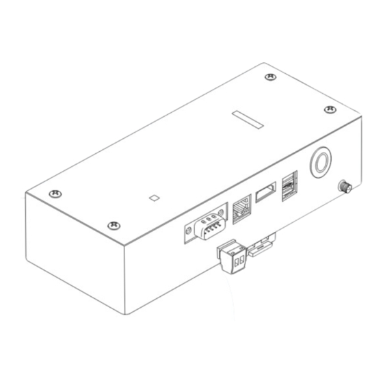
Page 9: Component Names
BN interface Service Manual 2-2. Component Names External component names Name Function 12V DCIN Connect the power adapter (For service) Ethernet (LAN) Connect to the Building Management System Shutdown button Shutdown or switch to air conditioner search mode LINK(Uh) Connect the central control wiring... - Page 10 BN interface Service Manual Internal component names SW100 Uh Line termination resistance setting switch bit1:use, bit2:not use Refer to " Termination resistance setting" (P.80) Shutdown button Shutdown function / air conditioner search mode function button Use this button to stop BACnet process and network process of the BN interface or to start up in the air conditioner search mode.
- Page 11 BN interface Service Manual LED names LED color POWER Power indicator RS485 Green Not use LINK1(Uh) Orange Uh Line communication status indicator LINK2(Uh) Orange Not use ERROR Uh Line communication error indicator Green BACnet communication status indicator, setting error indicator Link LED LAN port LED1 Green...
-
Page 12: Internal Board Block Diagram
BN interface Service Manual 2-3. Internal board block diagram CPU BOARD Ethernet (LAN) 12V DCIN RTC_BAT CR2032 battery CN1 (not used) TU2C-LINK communication board Shutdown button CN08 CPU BOARD CN21 12V DCOUT LINK (Uh) 12V DCIN Phoenix Contact GMSTB 2.5/2-ST CPU BOARD ... -
Page 13: Software Specifications
- "Network Object and Variables Specifications (DEC0329401)" 3-1. BACnet Communication Specifications ANNEX A - PROTOCOL IMPLEMENTATION CONFORMANCE STATEMENT (NORMATIVE) BACnet Protocol Implementation Conformance Statement Vender Name Toshiba Carrier Corporation (ID:129) Product Name BN Interface Product Model Number BMS-IFBN1281U-UL BACnet Protocol Revision... - Page 14 BN interface Service Manual BACnet Standardized Device Profile (Annex L): BACnet Operator Workstation (B-OWS) BACnet Building Controller (B-BC) BACnet Advanced Application Controller (B-AAC) BACnet Application Specific Controller (B-ASC) BACnet Smart Sensor (B-SS) BACnet Smart Actuator (B-SA) BACnet Interoperability Building Blocks Supported (Annex K): BIBB Name Designation ReadProperty-B...
- Page 15 BN interface Service Manual Standard Object Types Supported: Dynamically Dynamically Object-Type Supported Creatable Deletable Accumulator Analog Input Analog Output Analog Value Binary Input Binary Output Binary Value Calendar Command Device Event Enrollment File Group Loop Multi-state Input ...
- Page 16 BN interface Service Manual Networking Options: Router, Clause 6 - List all routing configurations, e.g., ARCNET-Ethernet, Ethernet-MS/TP, etc. Annex H, BACnet Tunneling Router over IP BACnet/IP Broadcast Management Device (BBMD) Does the BBMD support registrations by Foreign Devices? Character Sets Supported: Indicating support for multiple character sets does not imply that they can all be supported simultaneously.
-
Page 17: Connectable Air Conditioners
BN interface Service Manual 3-2. Connectable Air Conditioners Item Specification Number of indoor units 128 units maximum In the following case, the number of indoor units is 64. - When used with controller for TCC-LINK old communication - When replacing a failed BMS-IFBN640TLUL CAUTION A central address must be set for the indoor units. - Page 18 BN interface Service Manual...
- Page 19 BN interface Service Manual...
- Page 20 BN interface Service Manual...
- Page 21 BN interface Service Manual NOTE BN interface acquires indoor unit device information and creates an air conditioner settings file when Air-Conditioning Search Mode is executed during a test run. As a result of this, some of the objects and settings listed are not output in the air conditioner settings file. (1) Ventilation ON/OFF Status can be used in the following situations.
- Page 22 BN interface Service Manual NOTE Notes on controlling VRF Dx-coil controller (TCB-IFDMX01UP-E, TCB-IFDMR01UP-E). (1) VRF Dx-coil controller is in the “TA mode” or the "TF mode" setting Function Monitoring Controlling ON / OFF Operation mode Setting temperature ...
- Page 23 BN interface Service Manual...
- Page 24 BN interface Service Manual...
- Page 25 BN interface Service Manual...
- Page 26 BN interface Service Manual...
- Page 27 BN interface Service Manual...
- Page 28 BN interface Service Manual...
- Page 29 BN interface Service Manual...
- Page 30 BN interface Service Manual...
- Page 31 BN interface Service Manual...
- Page 32 BN interface Service Manual...
- Page 33 BN interface Service Manual...
- Page 34 BN interface Service Manual...
- Page 35 BN interface Service Manual...
- Page 36 BN interface Service Manual...
- Page 37 BN interface Service Manual...
- Page 38 BN interface Service Manual...
- Page 39 BN interface Service Manual...
- Page 40 BN interface Service Manual...
- Page 41 BN interface Service Manual...
- Page 42 BN interface Service Manual...
- Page 43 BN interface Service Manual...
- Page 44 BN interface Service Manual...
- Page 45 BN interface Service Manual...
- Page 46 BN interface Service Manual...
- Page 47 BN interface Service Manual...
- Page 48 BN interface Service Manual...
- Page 49 BN interface Service Manual...
- Page 50 BN interface Service Manual...
- Page 51 BN interface Service Manual...
- Page 52 BN interface Service Manual...
- Page 53 BN interface Service Manual...
- Page 54 BN interface Service Manual...
- Page 55 BN interface Service Manual...
- Page 56 BN interface Service Manual...
- Page 57 BN interface Service Manual...
- Page 58 BN interface Service Manual...
- Page 59 BN interface Service Manual...
- Page 60 BN interface Service Manual...
- Page 61 BN interface Service Manual...
- Page 62 BN interface Service Manual...
- Page 63 BN interface Service Manual...
- Page 64 BN interface Service Manual...
- Page 65 BN interface Service Manual...
- Page 66 BN interface Service Manual...
- Page 67 BN interface Service Manual...
- Page 68 BN interface Service Manual...
- Page 69 BN interface Service Manual...
- Page 70 BN interface Service Manual...
- Page 71 BN interface Service Manual...
- Page 72 BN interface Service Manual...
-
Page 73: Factory Default Settings
BN interface Service Manual Factory default settings Item Factory default setting IP address 192.168.1.100 IP address of BN interface Subnet mask 255.255.255.0 UDP port 47808 (0xBAC0) Device object instance number Use 1Byte of Last byte of IP Address number. Uh Line termination resistance select switch Indoor unit configuration setting 10 VRF indoor units (details below) Temperature unit (Celsius/Fahrenheit) - Page 74 BN interface Service Manual Central Control address Line address Indoor Unit address Indoor unit type undefined undefined undefined undefined undefined undefined undefined undefined undefined undefined undefined undefined undefined undefined undefined undefined undefined undefined undefined undefined undefined undefined undefined undefined undefined undefined undefined undefined...
- Page 75 BN interface Service Manual Central Control address Line address Indoor Unit address Indoor unit type undefined undefined undefined undefined undefined undefined undefined undefined undefined undefined undefined undefined undefined undefined undefined undefined undefined undefined undefined undefined undefined undefined undefined undefined undefined undefined undefined undefined...
-
Page 76: Items Included With The Product
BN interface Service Manual Items included with the product BMS-IFBN1281U-UL Component Q'ty Remarks BN interface equipment Power adapter BN interface power supply Pin terminal Uh Line caulked connectors Mounting bracket (DIN rail) Use screws to secure the unit in locations without DIN rails (walls, etc.) Screws (M4 x 12) For securing the DIN rails Installation Manual... -
Page 77: Installation
BN interface Service Manual Installation REQUIREMENT Do not install the unit in any of the following places. • Humid or wet place • Dusty place • Place exposed to direct sunlight • Place where there is a TV set or radio within 3 ft •... - Page 78 BN interface Service Manual Installation Space and Maintenance Space A side space for connecting through cable inlets and an upper space for maintenance must be reserved before installation. The other sides can be adjacent to surrounding objects. 3.94" 100 mm 3.94"...
-
Page 79: Power And Signal Line Connections
BN interface Service Manual Power and signal line connections Cables Use the following cable for signal line connections. (Procured locally) Line Description Type 2-core shielded wires For Uh Line Wire size Refer to “Design of Control Wiring” (P.81 to P.84). Length LAN cable (higher than Category 5, UTP) Type... - Page 80 BN interface Service Manual Termination resistance setting • TU2C-LINK / TCC-LINK termination resistance setting ....<For TCC-LINK> Leave just 1 line of the termination resistance in the interface board of the outdoor unit (centre unit) ON, and turn all the others OFF. (Refer to the wiring diagram attached to the outdoor unit for the position of SW.) <For TU2C-LINK>...
- Page 81 BN interface Service Manual Design of Control Wiring Communication method and model name The TU2C-LINK model (U series) can be used together with previous models (other than U series). For details of the model and communication method, see the following table. Communication method TU2C-LINK (U series) TCC-LINK (other than U series)
- Page 82 BN interface Service Manual When the connected outdoor unit is Super Multi u series (U series) Follow the wiring specifications in the table below even when there is a mix of U series and non-U series in the connected indoor units or remote controllers.
- Page 83 BN interface Service Manual When the connected outdoor units are other than Super Multi u series (U series) Wiring specifications Communication line Item Control wiring between indoor and outdoor units and central control wiring AWG16: Up to 3281 ft (1000 m) Wire diameter AWG14: Up to 6560 ft (2000 m) Wire type...
- Page 84 BN interface Service Manual When connecting to a previous model light commercial, air to air heat exchanger, air to water heat pump, or general purpose equipment control interface Follow the wiring specifications in the table below even when there is a mix of U series and non-U series in the connected indoor units or remote controllers.
-
Page 85: Startup And Shutdown
BN interface Service Manual Startup and Shutdown 8-1. Startup The BN interface has no power switch. Plug the cable into the socket and then turn the socket on. The BN interface LED display changes as follows when it is powered. LED display changes at startup LED display changes at startup * Control interval (time length of 1 cell): 200 ms... -
Page 86: Test Run
BN interface Service Manual Test run To perform test run of the BN interface, BACnet communication settings and the equipment data of the connected indoor units are required. Settings, descriptions and configuration method before test run Factory default Device Item Configuration method, device, software settings... - Page 87 BN interface Service Manual Configuring settings (1) Turn on the BN interface, and wait until it reaches step 5 of the startup procedure. Refer to “Startup and Shutdown” for details. (2) Hold down the BN interface Shutdown button for at least 4 seconds. [LED-L1 Step1] (3) BN interface will start reading the equipment data of the indoor units.
-
Page 88: Search Results File (Searchobjectlog.tsv)
BN interface Service Manual 9-3. Search Results File (SearchObjectLog.tsv) Results of the air conditioner search are output in the search results file. These files are text files separated by tabs. Indoor unit detection result 1.Execution day/time..... (1)The date and time the search was executed 2.IP address........ - Page 89 BN interface Service Manual Example 1: 5 indoor units, central control addresses 1 to 5, search completed normally 1.Execution day/time “2021/05/26 13:15:26.50” 2.IP address 192.168.1.100 3.No. of indoor units No. of outdoor header units , follower units 0 4.Message <Info> Outdoor unit search invalid. 5.TCC-LINK board information BN-I/F address 0x0401...
-
Page 90: Led Display During Normal Operation
BN interface Service Manual Example 2: Duplicate central control addresses, indoor unit information Ri** could not be acquired 1.Execution day/time “2021/05/26 13:15:26.50” 2.IP address 192.168.1.100 3.No. of indoor units No. of outdoor header units , follower units 0 4.Message <Info> Outdoor unit search invalid. 5.TCC-LINK board information BN-I/F address 0x0401... -
Page 91: Engineering Tool
Engineering Tool Refer to the engineering tool manual for details. Obtaining the Engineering Tool ”Setting File Creation Software2” Engineering tool and manuals can be downloaded from the TOSHIBA CARRIER “THGP” website. (https://global-portal.toshiba-carrier.co.jp/software/global/bms) 10-1. IP Address Setting The default BN interface IP address is set when shipped. Change it using the engineering tool. -
Page 92: Bacnet Device Object Instance Number Setting
BN interface Service Manual 10-2. BACnet Device Object Instance Number Setting The instance number of the BACnet Device object is set when shipped according to the following rule. Change the instance number using the engineering tool. • Use 1Byte of Last byte of IP Address number (1) Select “2: User Setting”... -
Page 93: Acquiring The Search Results File (Searchobjectlog.tsv)
BN interface Service Manual 10-3. Acquiring the Search Results File (SearchObjectLog.tsv) Follow the “SearchObjectLog Download” function procedure in the engineering tool to download the search results file (SearchObjectLog.tsv) to a PC from the BN interface. “SearchObjectLog Download” function procedure • Execute the “Initialization Tool” submenu in the Tool menu on the Main Menu screen of the engineering tool. •... -
Page 94: Searching For The Bn Interface Ip Address
BN interface Service Manual • Execute the “SearchObjectLog Download” submenu in the Tool menu of the Initialization Tool. 10-4. Searching for the BN interface IP Address If you are unsure of the BN interface IP address, find it using the “IP Address Search” function. [IP Address Search] in the [Tool] menu... - Page 95 BN interface Service Manual Troubleshooting 11-1. During test runs Problem Cause Action No indoor units can be found The indoor units and outdoor units are Check that the indoor units and outdoor units (The number of indoor units turned off. are turned on.
- Page 96 BN interface Service Manual Problem Cause Action A request frame was sent to • The IP Address or network mask setting is Check the following. the BN interface via BACnet wrong • Whether a response is sent when a ping communication but no command is sent from a PC.
- Page 97 BN interface Service Manual 11-2. When starting up BN interface Problem Cause Action There is an error in the settings file. • Execute Air-Conditioning Search Mode again. CAUTION The indoor units and outdoor units that are the target of the search must be turned on when Air-Conditioning Search Mode is executed.
- Page 98 BN interface Service Manual Problem Cause Action The status of an indoor unit When the BN interface and air conditioning Confirm whether power is being supplied to the acquired by BACnet management controller are not being used indoor and outdoor units. communication differs from together, the "LINK(Uh)"...
- Page 99 BN interface Service Manual 11-4. Directly After Changing the microSD Card (Service Component) Problem Cause Action Startup step 1 The BN interface internal microSD card has Check that the microSD card is inserted The LED display does not malfunctioned. correctly. LED-L1 is unlit.
- Page 100 BN interface Service Manual Replacing Service Parts 12-1. Replacing the microSD Card (1) Turn off the BN interface. (2) Remove the 4 screws on the front panel of the BN interface. Screw BN interface TU2C-LINK Ethernet (LAN) 12V DCIN (3) Push the microSD card into the slot until you hear a click and remove the card. Slot...
- Page 101 BN interface Service Manual (4) Insert the microSD card into the slot and push it in until you hear a sound. Slot (5) Turn on the BN interface power, and operate as in a test run. CAUTION • Do not leave the card hanging out of the slot.
- Page 102 BN interface Service Manual 12-2. Replacing the Power Adaptor (1) Turn off the BN interface, and replace the power adaptor. (2) Remove the ferrite core from the power cord. (3) Attach the ferrite core to the replacement power cord in the same way. (Power adapter) 59.05"±0.78"...
- Page 103 BN interface Service Manual Service Component List For BMS-IFBN1281U-UL Component name Component code Outline Quantity used microSD card 4316W077 Specialized microSD card containing BN interface software Power adaptor 4316V581 Power adaptor for the BN interface CAUTION • The microSD card cannot be used with Windows. Do not insert it into a Windows PC. If the microSD card is inserted into a Windows PC, the contents may be corrupted.
- Page 104 BN interface Service Manual Systems in which the BN interface is used in conjunction with another air conditioning controller This chapter explains about systems in which the BN interface is used in conjunction with another air conditioning controller. NOTE As for the version of the Setting File Creation Software2, use v1.6.0.0 (March, 2023) or later. 14-1.
- Page 105 BN interface Service Manual 14-2-2. Preparation for the test run When using multiple BN interfaces, set different numbers for the IP addresses and the BACnet Device object instance numbers so that they do not overlap. IP address Instance number for BACnet Device object BN interface No.
- Page 106 BN interface Service Manual In the Setting File Creation Software2, enter the IP address for the BN interface and set the BACnet Device object numbers. Once these have been entered, upload the settings file to the BN interface from the Setting File Creation Software2. Once the settings file has been uploaded, the BN interface will automatically restart.
- Page 107 BN interface Service Manual 14-3. System for Combination Use with Smart BMS Manager 14-3-1. System configuration Wire the devices as shown below: Building Management System Line-1 Line-2 BN interface TU2C-LINK Ethernet (LAN) Uh Line BN interface TU2C-LINK Ethernet (LAN) Uh Line 14-3-2.
- Page 108 BN interface Service Manual 14-3-3. Procedure for test run (1) Set the line addresses, unit addresses, and central control address for the indoor units. (2) Conduct a test run of the Smart BMS Manager. (3) Turn off the power to the Smart BMS Manager. (4) Power on the BN interface.
- Page 109 BN interface Service Manual NOTE Before executing air-conditioning search mode, be sure to turn off the power to Smart BMS Manager. If a communication collision occurs between Smart BMS Manager and the BN interface at a Uh Line bus, proper communication with the indoor units will be interrupted, preventing creation of the settings file.
- Page 110 BN interface Service Manual 14-4. System for Combination Use with Touch Screen Controller (BMS- CT2560U-UL) 14-4-1. System configuration Wire the devices as shown below: Building Management System TOUCH SCREEN CONTROLLER Line-1 Line-2 BN interface TU2C-LINK Ethernet (LAN) Uh Line BN interface TU2C-LINK Ethernet (LAN) Uh Line 14-4-2.
- Page 111 BN interface Service Manual 14-4-3. Procedure for test run (1) Set the line addresses, unit addresses, and central control address for the indoor units. (2) Conduct a test run of the Touch Screen Controller. (3) Turn off the power to the Touch Screen Controller. (4) Power on the BN interface.
- Page 112 BN interface Service Manual NOTE Before executing air-conditioning search mode, be sure to turn off the power to Touch Screen Controller. If there is a communication collision on Uh Line between the Touch Screen Controller and BN interface, the indoor units cannot be properly communicated with, and a setting file cannot be created.
- Page 113 BN interface Service Manual 14-5. System for Combination Use with Central Remote Controller (TCB- SC640U-UL) If using 65 or more indoor units, use 2 central remote controllers. 14-5-1. System configuration Wire the devices as shown below: Building Management System 1st Central Controller BN interface 2nd Central Controller TU2C-LINK Ethernet (LAN)
- Page 114 BN interface Service Manual In the Setting File Creation Software2, enter the IP address for the BN interface and set the BACnet Device object numbers. Once these have been entered, upload the settings file to the BN interface from the Setting File Creation Software2. Once the settings file has been uploaded, the BN interface will automatically restart.
- Page 115 BN interface Service Manual Old BN interface product replacement 15-1. BMS-IFBN640TLUL The following explains the setting procedure for using BMS-IFBN1281U-UL as BMS-IFBN640TLUL in the case of BMS- IFBN640TLUL failure. Product before replacement Product after replacement BMS-IFBN640TLUL BMS-IFBN1281U-UL NOTE As for the version of the Setting File Creation Software2, use v1.6.0.0 (March, 2023) or later. (1) Following the procedure described in “10 Engineering Tool”, create a setting file for BMS-IFBN1281U-UL with Setting File Creation Software2.
- Page 116 Installation Manual (BMS-IFBN1281U-UL)
- Page 117 Montážnej príručky, Licenčnej zmluvy a Informácií o licencii / [Slovenščina] Prenos navodil za montažo, licenčne pogodbe in licenčnih informacij / [Svenska] Nedladdning av Installationshandbok, Licensavtal och Licensinformation / [Türkçe] Kurulum kılavuzu, Lisans Sözleşmesi ve Lisans Bilgileri İndirme / [中文] 安装手册,许可证协议和 许可证信息下载 https://www.toshiba-carrier.co.jp/global/manual/bms-ifbn1281u.htm...
- Page 118 BN interface Installation Manual Contents Precautions for safety ........... . 2 Introduction.
-
Page 119: Precautions For Safety
BN interface Installation Manual Precautions for safety The following instructions must be observed. • Carefully read these "Precautions for Safety" before installation, and perform installation work safely. • These precautions contain important information regarding safety. • After installation work, carry out an operation trial to confirm that there are no problems, and explain to the customer how to operate and maintain the system. -
Page 120: Introduction
BN interface Installation Manual Introduction Overview The BN interface refers to equipment used for controlling Building Management Systems (Procured locally) and air conditioners “TU2C-LINK Uh Line (hereinafter, referred to as Uh Line) compatible models” through communications via a network to enable central control. - Page 121 BN interface Installation Manual (Power adapter) 59.05"±0.78" 4.33"±0.01" 1.24" (110.0±0.5) (1500.0±20.0) (31.5) FERRITE AS REQUIRED 1.29"±0.01" 1.18"± 0.19" (33.0±0.5) (30±5) (29.6±0.5) 1.16"±0.01" WIRE NO:1185 0.01" (0.5) GAUGE:16AWG (BLACK) Ø1/2" (Ø12.0) 78.74"±1.96" Ø7/32" SPEC LABEL (2000±50) (Ø5.5) Ø3/32" (Ø2.5) Component Names Unit: inch (mm) Name Function...
-
Page 122: Installation
BN interface Installation Manual Installation REQUIREMENT Do not install the unit in any of the following places. • Humid or wet place • Dusty place • Place exposed to direct sunlight • Place where there is a TV set or radio within 3 ft •... - Page 123 BN interface Installation Manual Installation Space and Maintenance Space A side space for connecting through cable inlets and an upper space for maintenance must be reserved before installation. The other sides can be adjacent to surrounding objects. 3.94" 100 mm 3.94"...
-
Page 124: Power And Signal Line Connections
BN interface Installation Manual Power and signal line connections Cables Use the following cable for signal line connections. (Procured locally) Line Description Type 2-core shielded wires For Uh Line Wire size Refer to "Design of Control Wiring" (P.10 to P.13) Length LAN cable (higher than Category 5, UTP) Type... - Page 125 BN interface Installation Manual Example of System Wiring Connections BN interface Power adapter Power Supply Touch Screen Controller BMS-CT2560U-UL Building Management System LINK1 LINK2 Uh Line / TCC-LINK Outdoor unit Outdoor unit Indoor unit Remote Remote Indoor unit controller controller...
- Page 126 BN interface Installation Manual Termination resistance setting • TU2C-LINK / TCC-LINK termination resistance setting ....<For TCC-LINK> Leave just 1 line of the termination resistance in the interface board of the outdoor unit (centre unit) ON, and turn all the others OFF. (Refer to the wiring diagram attached to the outdoor unit for the position of SW.) <For TU2C-LINK>...
- Page 127 BN interface Installation Manual Design of Control Wiring Communication method and model name The TU2C-LINK model (U series) can be used together with previous models (other than U series). For details of the model and communication method, see the following table. Communication method TU2C-LINK (U series) TCC-LINK (other than U series)
- Page 128 BN interface Installation Manual When the connected outdoor unit is Super Multi u series (U series) Follow the wiring specifications in the table below even when there is a mix of U series and non-U series in the connected indoor units or remote controllers.
- Page 129 BN interface Installation Manual When the connected outdoor units are other than Super Multi u series (U series) Wiring specifications Communication line Item Control wiring between indoor and outdoor units and central control wiring AWG16: Up to 3281 ft (1000 m) Wire diameter AWG14: Up to 6560 ft (2000 m) Wire type...
- Page 130 BN interface Installation Manual When connecting to a previous model light commercial, air to air heat exchanger, air to water heat pump, or general purpose equipment control interface Follow the wiring specifications in the table below even when there is a mix of U series and non-U series in the connected indoor units or remote controllers.
-
Page 131: Settings
BN interface Installation Manual Settings 3-1. Switch setting SW100 Uh Line termination resistance setting switch bit1:use, bit2:not use Refer to "Termination resistance setting" (P.9) Shutdown button Shutdown function / air conditioner search mode function button Use this button to stop BACnet process and network process of the BN interface or to start up in the air conditioner search mode. -
Page 132: Led
BN interface Installation Manual 3-2. LED LED color POWER Power indicator RS485 Green Not use LINK1(Uh) Orange Uh Line communication status indicator LINK2(Uh) Orange Not use ERROR Uh Line communication error indicator Green BACnet communication status indicator, setting error indicator Factory default settings Item Factory default setting... -
Page 133: Test Run
BN interface Installation Manual Test run To perform test run of the BN interface, BACnet communication settings and the equipment data of the connected indoor units are required. Items to be set during trial run Equipment Item Setting method Use the DIP switch on the outdoor Outdoor unit Uh Line address Line address... -
Page 134: Setting Up Equipment Data In The Indoor Unit
BN interface Installation Manual 5-2. Setting up equipment data in the indoor unit Obtain the equipment data of the indoor unit that is controlled by the BN interface from the indoor unit via the Uh Line communication cable. Preparing to set up equipment data in the indoor unit •... -
Page 135: Cause Of Problem Occurring During Setup
BN interface Installation Manual 5-3. Cause of problem occurring during setup Cause of problem Cause Action The indoor and outdoor units have not been Make sure that indoor and outdoor units are turned on. turned on. The indoor and outdoor units are being Make sure that indoor and outdoor units are initialized and it is not possible to turned on. - Page 136 Copyright © 2023 TOSHIBA CARRIER CORPORATION, ALL Rights Reserved. Revision record Number The contents of modification Page Date First issue Feb., 2023 13, 18-20, Revision 1 Added Dual Set Point Oct., 2023 23, 36-39, 96...