
Related Manuals for Huawei SUN2000-33KTL-JP


Summary of Contents for Huawei SUN2000-33KTL-JP
- Page 1 SUN2000-(33KTL, 40KTL)-JP User Manual Issue Date 2019-06-30 HUAWEI TECHNOLOGIES CO., LTD.
- Page 2 Notice The purchased products, services and features are stipulated by the contract made between Huawei and the customer. All or part of the products, services and features described in this document may not be within the purchase scope or the usage scope. Unless otherwise specified in the contract, all statements, information, and recommendations in this document are provided "AS IS"...
-
Page 3: About This Document
About This Document About This Document Purpose This document describes the SUN2000-33KTL-JP/40KTL-JP (SUN2000 for short) in terms of its installation, electrical connections, commissioning, maintenance, and troubleshooting. Understand the safety information and get familiar with the SUN2000 functions and features before installing and operating the SUN2000. - Page 4 Issue 03 (2017-06-05) Updated Installation Environment Requirements 4.3 Wall-mounting the SUN2000. Updated Installation Environment Requirements 4.4 Support-mounting the SUN2000. Updated 9.1 Routine Maintenance. Issue 02 (2016-09-30) Modified the parameters in 11 Technical Specifications. Issue 07 (2019-06-30) Copyright © Huawei Technologies Co., Ltd.
- Page 5 SUN2000-(33KTL, 40KTL)-JP User Manual About This Document Issue 01 (2016-07-30) This issue is the first official release. Issue 07 (2019-06-30) Copyright © Huawei Technologies Co., Ltd.
-
Page 6: Table Of Contents
5.4 Connecting DC Input Power Cables ........................... 47 5.5 Connecting Communications Cables .......................... 55 5.5.1 Communication Mode Description .......................... 55 5.5.2 Connecting RS485 Communications Cables ......................57 5.6 Closing the Maintenance Compartment Door ......................62 Issue 07 (2019-06-30) Copyright © Huawei Technologies Co., Ltd. - Page 7 10.1 Removing the SUN2000 ............................115 10.2 Packing the SUN2000 ............................. 115 10.3 Disposing of the SUN2000 ............................. 115 11 Technical Specifications ......................116 A Power Grid Codes ........................120 B Acronyms and Abbreviations ....................122 Issue 07 (2019-06-30) Copyright © Huawei Technologies Co., Ltd.
-
Page 8: Safety Precautions
Before performing operations, read through this manual and follow all the precautions to prevent accidents. The safety precautions provided in this document do not cover all the safety precautions. Huawei shall not be liable for any consequence caused by the violation of the safety operation regulations and design, production, and usage standards. - Page 9 Do not touch an operating inverter because the heat sinks may have a temperature of greater than 60° C and may cause burns when the inverter is operating. Follow local laws and regulations when operating the equipment. Maintenance and Replacement Issue 07 (2019-06-30) Copyright © Huawei Technologies Co., Ltd.
- Page 10 Rectify any faults that may compromise the inverter security performance before powering on the inverter again. Observe ESD precautions during the maintenance. For personal safety, wear insulation gloves and protective shoes. Issue 07 (2019-06-30) Copyright © Huawei Technologies Co., Ltd.
-
Page 11: Overview
The SUN2000 is a three-phase grid-tied PV string inverter that converts the DC power generated by PV strings into AC power and feeds the power into the power grid. Models Figure 2-1 shows a model number of the SUN2000, using SUN2000-33KTL-JP as an example. Figure 2-1 Model number description Table 2-1 describes the rated output power and voltage of all models of SUN2000. - Page 12 Figure 2-3 Power grid mode supported by the SUN2000 The SUN2000 is mainly used for medium-voltage power grids. It delivers three-phase, three-wire output, which is then fed to a medium-voltage power grid through a step-up transformer. Issue 07 (2019-06-30) Copyright © Huawei Technologies Co., Ltd.
-
Page 13: Appearance
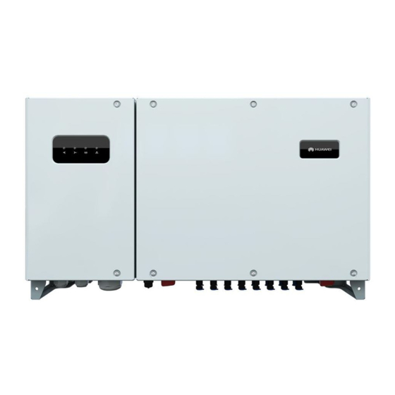
SUN2000-(33KTL, 40KTL)-JP User Manual 2 Overview 2.2 Appearance Dimensions Figure 2-4 SUN2000 dimensions (including the mounting plate) Figure 2-5 Mounting bracket dimensions SUN2000 Front View Figure 2-6 shows the SUN2000 front view. Issue 07 (2019-06-30) Copyright © Huawei Technologies Co., Ltd. - Page 14 0.5s and then off for 0.5s) communications data normally. Green off The SUN2000 receives no communications data for 10s. Alarm/Maintenanc Alarm status Blinking red at long A warning alarm is Issue 07 (2019-06-30) Copyright © Huawei Technologies Co., Ltd.
- Page 15 After the USB flash drive, WLAN module, Bluetooth module, or USB data cable is removed, the indicator shows the alarm state. SUN2000 Rear View Figure 2-7 shows the SUN2000 rear view. Issue 07 (2019-06-30) Copyright © Huawei Technologies Co., Ltd.
- Page 16 Waterproof cable connector (inner AC OUTPUT 1 diameter: 37–44 mm) Waterproof cable connector (inner AC OUTPUT 2 diameter: 24–32 mm) USB port DC switch 1 DC SWITCH 1 DC switch 2 DC SWITCH 2 Issue 07 (2019-06-30) Copyright © Huawei Technologies Co., Ltd.
-
Page 17: Label Description
SUN2000. Residual voltage exists after the SUN2000 is powered off. It takes 5 minutes for the SUN2000 to discharge to the safe voltage. Issue 07 (2019-06-30) Copyright © Huawei Technologies Co., Ltd. - Page 18 Nameplate On the side of the SUN2000, there is a nameplate that contains the model information, technical specifications, and compliance symbols, as shown in Figure 2-9. Issue 07 (2019-06-30) Copyright © Huawei Technologies Co., Ltd.
- Page 19 SUN2000-(33KTL, 40KTL)-JP User Manual 2 Overview Figure 2-9 Nameplate of the SUN2000-33KTL-JP (1) Trademark and product model (2) Important technical specifications (3) Compliance symbols (4) Company name and country of manufacture The nameplate figure is for reference only. Table 2-4 describes the compliance symbols.
-
Page 20: Working Principle
SUN2000 conceptual diagram. Figure 2-10 SUN2000 conceptual diagram Working Modes The SUN2000 can work in standby, operating, or shutdown mode. Figure 2-11 shows the relationship between the three working modes. Issue 07 (2019-06-30) Copyright © Huawei Technologies Co., Ltd. - Page 21 In standby or operating mode, the SUN2000 enters the shutdown mode Shutdown after detecting a fault or shutdown command. In shutdown mode, the SUN2000 enters the standby mode after detecting a startup command or that a fault is rectified. Issue 07 (2019-06-30) Copyright © Huawei Technologies Co., Ltd.
-
Page 22: Storage
Periodic inspections are required during the storage. Replace the packing materials as necessary. If the SUN2000 has been long-term stored, inspections and tests should be conducted by qualified personnel before put into use. Issue 07 (2019-06-30) Copyright © Huawei Technologies Co., Ltd. -
Page 23: System Installation
After unpacking the inverter, check that the deliverables are intact and complete. If any damage is found or any component is missing, contact the dealer. For details about the number of deliverables, see the Packing List in the packing case. Issue 07 (2019-06-30) Copyright © Huawei Technologies Co., Ltd. -
Page 24: Tools
Torque wrench With an open end of 18 Secures bolts and locking caps. mm, 33 mm, 52 mm, or 65 mm Diagonal pliers Cut cable ties. Wire stripper Peels cable jackets. Issue 07 (2019-06-30) Copyright © Huawei Technologies Co., Ltd. - Page 25 UTXTC0005 (Amphenol) is used to crimp metal cold forming contacts. H4TC0003 (Amphenol) is used to crimp metal stamping forming contacts. RJ45 crimping tool Prepares RJ45 connectors for communications cables. Issue 07 (2019-06-30) Copyright © Huawei Technologies Co., Ltd.
- Page 26 Cleans up dust after drilling holes. Multimeter DC voltage measurement Measures voltages. range: ≥ 1100 V DC Diameter: ≤ 10 mm Marker Marks signs. Measuring tape Measures distances. Level Levels hole positions. Issue 07 (2019-06-30) Copyright © Huawei Technologies Co., Ltd.
- Page 27 Protects an operator from dust inhalation during hole drilling. Hydraulic pliers Crimp OT/DT terminals. Heat shrink tubing Wraps the cable crimping area of an OT/DT terminal. Heat gun Heat-shrinks a tube. Issue 07 (2019-06-30) Copyright © Huawei Technologies Co., Ltd.
-
Page 28: Wall-Mounting The Sun2000
SUN2000 disturb residents. Installation Angle Requirements Install the SUN2000 vertically or at a maximum back tilt of 15 degrees to facilitate heat dissipation. Issue 07 (2019-06-30) Copyright © Huawei Technologies Co., Ltd. - Page 29 The SUN2000 dimensions (W x H x D, including the mounting bracket) are 930 mm x 550 mm x 283 mm. Reserve enough clearance around the SUN2000 to ensure sufficient space for installation and heat dissipation, as shown in Figure 4-4. Issue 07 (2019-06-30) Copyright © Huawei Technologies Co., Ltd.
- Page 30 When installing multiple SUN2000s, install them in horizontal mode if sufficient space is available and install them in triangle mode if no sufficient space is available. The stacked installation mode is not recommended. Figure 4-5 Horizontal installation mode (recommended) Issue 07 (2019-06-30) Copyright © Huawei Technologies Co., Ltd.
- Page 31 SUN2000-(33KTL, 40KTL)-JP User Manual 4 System Installation Figure 4-6 Triangle installation mode (recommended) Issue 07 (2019-06-30) Copyright © Huawei Technologies Co., Ltd.
-
Page 32: Moving The Sun2000
When placing the SUN2000 on the floor, put foam or paper under the SUN2000 to protect its cover. Procedure Step 1 Arrange two persons to hold the handles on both sides of the SUN2000, as shown in Figure 4-8. Issue 07 (2019-06-30) Copyright © Huawei Technologies Co., Ltd. -
Page 33: Installing The Mounting Bracket
The SUN2000 mounting bracket has 16 tapped holes in four groups. Mark any hole in each group based on site requirements and mark four holes in total. Two round holes are preferred. Procedure Step 1 Remove the security torx wrench from the mounting bracket and set it aside. Issue 07 (2019-06-30) Copyright © Huawei Technologies Co., Ltd. - Page 34 Step 3 Drill holes using a hammer drill and install expansion bolts, as shown in Figure 4-13. Avoid drilling holes in the water pipes and power cables buried in the wall. An expansion bolt contains four parts, as shown in Figure 4-12. Issue 07 (2019-06-30) Copyright © Huawei Technologies Co., Ltd.
- Page 35 Step 4 Align the mounting bracket with the holes, insert expansion bolts into the holes through the mounting bracket, and tighten the expansion bolts to a torque of 45 N· m using an 18 mm socket wrench, as shown in Figure 4-14. Issue 07 (2019-06-30) Copyright © Huawei Technologies Co., Ltd.
-
Page 36: Installing The Sun2000
SUN2000 with one hand and the handle at the top with the other, as shown in Figure 4-15. To prevent personal injury caused by a falling SUN2000, keep balance when lifting the SUN2000 because it is heavy. Issue 07 (2019-06-30) Copyright © Huawei Technologies Co., Ltd. - Page 37 Step 4 Run a rope that is strong enough to bear the SUN2000 through the lifting eyes and hoist the SUN2000, as shown in Figure 4-16. When hoisting the SUN2000, keep balance to protect the SUN2000 from colliding with the wall or other objects. Figure 4-16 Hoisting a SUN2000 Issue 07 (2019-06-30) Copyright © Huawei Technologies Co., Ltd.
- Page 38 Step 6 Tighten the two security torx screws using a security torx wrench to a torque of 5 N· m, as shown in Figure 4-18. Figure 4-18 Tightening security torx screws ----End Issue 07 (2019-06-30) Copyright © Huawei Technologies Co., Ltd.
-
Page 39: Support-Mounting The Sun2000
The SUN2000 weighs 61 kg. Ensure that the installation surface is solid enough to bear the weight load. Installation Angle Requirements Install the SUN2000 vertically or at a maximum back tilt of 15 degrees to facilitate heat dissipation. Figure 4-19 Correct installation angles Issue 07 (2019-06-30) Copyright © Huawei Technologies Co., Ltd. - Page 40 The SUN2000 dimensions (W x H x D, including the mounting bracket) are 930 mm x 550 mm x 283 mm. Reserve enough clearance around the SUN2000 to ensure sufficient space for installation and heat dissipation, as shown in Figure 4-21. Figure 4-21 Installation space Issue 07 (2019-06-30) Copyright © Huawei Technologies Co., Ltd.
-
Page 41: Moving The Sun2000
Two round holes are preferred. Procedure Step 1 Remove the security torx wrench from the mounting bracket and set it aside. Figure 4-23 Removing a security torx wrench Issue 07 (2019-06-30) Copyright © Huawei Technologies Co., Ltd. - Page 42 45 N· m using an 18 mm socket wrench, as shown in Figure 4-26. Issue 07 (2019-06-30) Copyright © Huawei Technologies Co., Ltd.
-
Page 43: Installing The Sun2000
M12 bolt assemblies by yourself and use them together with the delivered M12 nuts. Figure 4-26 Securing a mounting bracket ----End 4.4.4 Installing the SUN2000 For details, see 4.3.4 Installing the SUN2000. Issue 07 (2019-06-30) Copyright © Huawei Technologies Co., Ltd. -
Page 44: Electrical Connections (2-Pin Spot-Check Terminal)
The cable colors shown in the electrical connection drawings provided in this chapter are for reference only. Select cables in accordance with local cable specifications (green-and-yellow wires are used for grounding only). 5.1 Opening the Maintenance Compartment Door Prerequisites Issue 07 (2019-06-30) Copyright © Huawei Technologies Co., Ltd. - Page 45 Figure 5-1 Removing screws Step 2 Open the maintenance compartment door and keep it open with the support bar. The support bar is bound to the enclosure base. Issue 07 (2019-06-30) Copyright © Huawei Technologies Co., Ltd.
-
Page 46: Installing A Ground Cable To The Pe Point
SUN2000s connected in parallel, connect the ground points of all SUN2000s to ensure equipotential connections to ground cables. Procedure Step 1 Strip an appropriate length of the insulation layer using a wire stripper, as shown in Figure 5-3. Issue 07 (2019-06-30) Copyright © Huawei Technologies Co., Ltd. - Page 47 Step 3 Remove the ground screws from the ground points. Step 4 Secure the ground cable using the ground screw and tighten the screw to a torque of 5 N•m using a security torx wrench. Issue 07 (2019-06-30) Copyright © Huawei Technologies Co., Ltd.
-
Page 48: Connecting Ac Output Power Cables
(U, V, and W) outdoor cable. If you connect a ground cable to the ground point in the maintenance compartment, you are recommended to use a four-core (U, V, W, and PE) outdoor cable. Table 5-1 describes the cable specifications. Issue 07 (2019-06-30) Copyright © Huawei Technologies Co., Ltd. - Page 49 If a copper-clad aluminum cable is used, use a copper wiring terminal. If an aluminum alloy cable is used, use a copper to aluminum adapter terminal or an aluminum wiring terminal with a copper to aluminum adapter washer. Issue 07 (2019-06-30) Copyright © Huawei Technologies Co., Ltd.
- Page 50 Ensure that the aluminum side of the washer contacts the aluminum wiring terminal, and the copper side contacts the AC terminal block. Figure 5-6 Requirements for OT terminals Procedure Step 1 Remove the AC terminal cover, as shown in Figure 5-7. Issue 07 (2019-06-30) Copyright © Huawei Technologies Co., Ltd.
- Page 51 Ensure that the jacket is in the maintenance compartment. Figure 5-8 Stripping an AC output power cable (three core wires) (A) Core wire (B) Insulation layer (C) Jacket Issue 07 (2019-06-30) Copyright © Huawei Technologies Co., Ltd.
- Page 52 If you connect a ground cable to the ground point in the maintenance compartment, tighten the ground screw using a 10 mm socket wrench with an extension rod to a torque of 5 N m. Issue 07 (2019-06-30) Copyright © Huawei Technologies Co., Ltd.
- Page 53 If a waterproof connector is not properly sealed, water or foreign matter could enter the maintenance compartment and damage the SUN2000. Figure 5-10 Connecting an AC output power cable (three core wires) Issue 07 (2019-06-30) Copyright © Huawei Technologies Co., Ltd.
-
Page 54: Connecting Dc Input Power Cables
When the SUN2000 is grid-tied, it is not allowed to maintain DC input power cables, such as connect or disconnect a string or a module in a string. Otherwise, electric shocks may occur. Issue 07 (2019-06-30) Copyright © Huawei Technologies Co., Ltd. - Page 55 The SUN2000 provides two DC switches, namely, DC SWITCH 1 and DC SWITCH 2. DC SWITCH 1 controls the first to the fourth routes of DC input terminals, while DC SWITCH 2 controls the fifth to the eighth routes of DC input terminals. Issue 07 (2019-06-30) Copyright © Huawei Technologies Co., Ltd.
- Page 56 4.5–7.8 industry (model: PV1-F) AWG) Rigid cables, such as armored cables, are not recommended, because poor contact may be caused by the bending of the cables. Positive and negative connectors Issue 07 (2019-06-30) Copyright © Huawei Technologies Co., Ltd.
- Page 57 Using other models of positive and negative metal terminals and DC connectors may result in serious consequences. The caused device damage is not covered under any warranty or service agreement. Procedure Step 1 Prepare positive and negative connectors. Issue 07 (2019-06-30) Copyright © Huawei Technologies Co., Ltd.
- Page 58 (1) Locator Figure 5-16 Preparing positive and negative connectors (using metal cold forming contacts) (1) Positive metal contact (cold forming) (2) Negative metal contact (cold forming) (3) Positive connector (4) Negative connector Issue 07 (2019-06-30) Copyright © Huawei Technologies Co., Ltd.
- Page 59 Step 3 Ensure that the DC input voltage of each PV string does not exceed 1100 V DC using a multimeter and check that the polarities of the DC input power cables are correct. Issue 07 (2019-06-30) Copyright © Huawei Technologies Co., Ltd.
- Page 60 SUN2000 until they snap into place, as shown in Figure 5-19. After the positive and negative connectors snap into place, pull the DC input power cables back to ensure that they are connected securely. Issue 07 (2019-06-30) Copyright © Huawei Technologies Co., Ltd.
- Page 61 Before removing the positive and negative connectors, ensure that the two DC switches are OFF. To remove the positive or negative connector from the SUN2000, insert a removal wrench into the notch shown in Figure 5-20 and press the wrench with an appropriate force. Issue 07 (2019-06-30) Copyright © Huawei Technologies Co., Ltd.
-
Page 62: Connecting Communications Cables
Figure 5-21 Communication mode for a single SUN2000 Figure 5-22 shows the communication mode for multiple SUN2000s. If multiple SUN2000s are used, connect all the SUN2000s in daisy chain mode over RS485 communications cables. Issue 07 (2019-06-30) Copyright © Huawei Technologies Co., Ltd. - Page 63 If the RS485 communication mode is selected, you are recommended to set PLC (MBUS) Communication to Disable on the SUN2000 app. PLC (MBUS) Communication is set to Enable by default. Issue 07 (2019-06-30) Copyright © Huawei Technologies Co., Ltd.
-
Page 64: Connecting Rs485 Communications Cables
When laying out communications cables, separate them from power cables and keep them away from strong signal sources to avoid communication interference. Functions of the RS485 terminal block Figure 5-23 Terminal block Table 5-4 describes functions of the RS485 terminal block. Issue 07 (2019-06-30) Copyright © Huawei Technologies Co., Ltd. - Page 65 Brown Procedure Method 1: Connecting to a terminal block (recommended) Remove an appropriate length of the jacket and core wire insulation layer from the communications cable using a wire stripper. Issue 07 (2019-06-30) Copyright © Huawei Technologies Co., Ltd.
- Page 66 Land the cables in the terminal block, and bond the shield layer to the ground point. When connecting the shielded cables, choose whether to crimp the M6 OT terminal based on site requirements. Issue 07 (2019-06-30) Copyright © Huawei Technologies Co., Ltd.
- Page 67 7.5 N•m. Method 2: Connecting to an RJ45 network port Insert the stripped core wires of the network cable to the RJ45 connector in sequence, as shown in Figure 5-29. Issue 07 (2019-06-30) Copyright © Huawei Technologies Co., Ltd.
- Page 68 Route the cables through the locking caps and then the COM1 port at the SUN2000 bottom. Insert the RJ45 connector into the RJ45 network port in the SUN2000 maintenance compartment. Figure 5-30 Connecting communications cables Bundle communications cables after connecting them. Issue 07 (2019-06-30) Copyright © Huawei Technologies Co., Ltd.
-
Page 69: Closing The Maintenance Compartment Door
7.5 N•m. ----End Follow-up Procedure Check that the cables are connected correctly and securely. Then seal the connectors. 5.6 Closing the Maintenance Compartment Door Procedure Step 1 Install the AC terminal cover. Issue 07 (2019-06-30) Copyright © Huawei Technologies Co., Ltd. - Page 70 Figure 5-33 Retrieving a support bar Step 3 Close the maintenance compartment door. Tighten the two screws on the maintenance compartment door using a security torx wrench to a torque of 5 N•m. Issue 07 (2019-06-30) Copyright © Huawei Technologies Co., Ltd.
- Page 71 If the floating nut used for securing the maintenance compartment door is missing, use the reserved floating nut shown in Figure 5-35. Figure 5-35 Removing a standby floating nut ----End Issue 07 (2019-06-30) Copyright © Huawei Technologies Co., Ltd.
-
Page 72: Electrical Connections (12-Pin Spot-Check Terminal)
The cable colors shown in the electrical connection drawings provided in this chapter are for reference only. Select cables in accordance with local cable specifications (green-and-yellow wires are used for grounding only). 6.1 Opening the Maintenance Compartment Door Prerequisites Issue 07 (2019-06-30) Copyright © Huawei Technologies Co., Ltd. - Page 73 Figure 6-1 Removing screws Step 2 Open the maintenance compartment door and keep it open with the support bar. The support bar is bound to the enclosure base. Issue 07 (2019-06-30) Copyright © Huawei Technologies Co., Ltd.
-
Page 74: Connecting A Ground Cable To The Pe Point
SUN2000s connected in parallel, connect the ground points of all SUN2000s to ensure equipotential connections to ground cables. Procedure Step 1 Strip an appropriate length of the insulation layer using a wire stripper, as shown in Figure 6-3. Issue 07 (2019-06-30) Copyright © Huawei Technologies Co., Ltd. - Page 75 Step 3 Remove the ground screws from the ground points. Step 4 Secure the ground cable using the ground screw and tighten the screw to a torque of 5 N•m using a security torx wrench. Issue 07 (2019-06-30) Copyright © Huawei Technologies Co., Ltd.
-
Page 76: Installing The Ac Output Power Cable
(U, V, and W) outdoor cable. If you connect a ground cable to the ground point in the maintenance compartment, you are recommended to use a four-core (U, V, W, and PE) outdoor cable. Table 6-1 describes the cable specifications. Issue 07 (2019-06-30) Copyright © Huawei Technologies Co., Ltd. - Page 77 If a copper-clad aluminum cable is used, use a copper wiring terminal. If an aluminum alloy cable is used, use a copper to aluminum adapter terminal or an aluminum wiring terminal with a copper to aluminum adapter washer. Issue 07 (2019-06-30) Copyright © Huawei Technologies Co., Ltd.
- Page 78 Ensure that the aluminum side of the washer contacts the aluminum wiring terminal, and the copper side contacts the AC terminal block. Figure 6-6 Requirements for OT terminals Procedure Step 1 Remove the AC terminal cover, as shown in Figure 6-7. Issue 07 (2019-06-30) Copyright © Huawei Technologies Co., Ltd.
- Page 79 Ensure that the jacket is in the maintenance compartment. Figure 6-8 Stripping an AC output power cable (three core wires) (A) Core wire (B) Insulation layer (C) Jacket Issue 07 (2019-06-30) Copyright © Huawei Technologies Co., Ltd.
- Page 80 If you connect a ground cable to the ground point in the maintenance compartment, tighten the ground screw using a 10 mm socket wrench with an extension rod to a torque of 5 N m. Issue 07 (2019-06-30) Copyright © Huawei Technologies Co., Ltd.
- Page 81 If a waterproof connector is not properly sealed, water or foreign matter could enter the maintenance compartment and damage the SUN2000. Figure 6-10 Connecting an AC output power cable (three core wires) Issue 07 (2019-06-30) Copyright © Huawei Technologies Co., Ltd.
-
Page 82: Installing The Dc Input Power Cable
N m. ----End Follow-up Procedure Check that the cables are connected correctly and securely, and then seal the cable holes with firestop putty. 6.4 Installing the DC Input Power Cable Prerequisites Issue 07 (2019-06-30) Copyright © Huawei Technologies Co., Ltd. - Page 83 The SUN2000 provides two DC switches, namely, DC SWITCH 1 and DC SWITCH 2. DC SWITCH 1 controls the first to the fourth routes of DC input terminals, while DC SWITCH 2 controls the fifth to the eighth routes of DC input terminals. Issue 07 (2019-06-30) Copyright © Huawei Technologies Co., Ltd.
- Page 84 4.5–7.8 industry (model: PV1-F) AWG) Rigid cables, such as armored cables, are not recommended, because poor contact may be caused by the bending of the cables. Positive and negative connectors Issue 07 (2019-06-30) Copyright © Huawei Technologies Co., Ltd.
- Page 85 Using other models of positive and negative metal terminals and DC connectors may result in serious consequences. The caused device damage is not covered under any warranty or service agreement. Procedure Step 1 Prepare positive and negative connectors. Issue 07 (2019-06-30) Copyright © Huawei Technologies Co., Ltd.
- Page 86 (1) Locator Figure 6-16 Preparing positive and negative connectors (using metal cold forming contacts) (1) Positive metal contact (cold forming) (2) Negative metal contact (cold forming) (3) Positive connector (4) Negative connector Issue 07 (2019-06-30) Copyright © Huawei Technologies Co., Ltd.
- Page 87 Step 3 Ensure that the DC input voltage of each PV string does not exceed 1100 V DC using a multimeter and check that the polarities of the DC input power cables are correct. Issue 07 (2019-06-30) Copyright © Huawei Technologies Co., Ltd.
- Page 88 SUN2000 until they snap into place, as shown in Figure 6-19. After the positive and negative connectors snap into place, pull the DC input power cables back to ensure that they are connected securely. Issue 07 (2019-06-30) Copyright © Huawei Technologies Co., Ltd.
- Page 89 Before removing the positive and negative connectors, ensure that the two DC switches are OFF. To remove the positive or negative connector from the SUN2000, insert a removal wrench into the notch shown in Figure 6-20 and press the wrench with an appropriate force. Issue 07 (2019-06-30) Copyright © Huawei Technologies Co., Ltd.
-
Page 90: Connecting Communications Cables
Figure 6-21 Communication mode for a single SUN2000 Figure 6-22 shows the communication mode for multiple SUN2000s. If multiple SUN2000s are used, connect all the SUN2000s in daisy chain mode over RS485 communications cables. Issue 07 (2019-06-30) Copyright © Huawei Technologies Co., Ltd. - Page 91 If the RS485 communication mode is selected, you are recommended to set PLC (MBUS) Communication to Disable on the SUN2000 app. PLC (MBUS) Communication is set to Enable by default. Issue 07 (2019-06-30) Copyright © Huawei Technologies Co., Ltd.
-
Page 92: Installing The Rs485 Communications Cable
Port definitions of the RS485 terminal block Figure 6-23 Terminal block Table 6-4 lists the port definitions of the RS485 terminal block. Issue 07 (2019-06-30) Copyright © Huawei Technologies Co., Ltd. - Page 93 Brown Procedure Method 1: Connecting to a terminal block (recommended) Remove an appropriate length of the jacket and core wire insulation layer from the communications cable using a wire stripper. Issue 07 (2019-06-30) Copyright © Huawei Technologies Co., Ltd.
- Page 94 Land the cables in the terminal block, and bond the shield layer to the ground point. When connecting the shielded cables, choose whether to crimp the M6 OT terminal based on site requirements. Issue 07 (2019-06-30) Copyright © Huawei Technologies Co., Ltd.
- Page 95 (8) Brown Crimp the RJ45 connector using a crimping tool. Remove the locking cap from the COM1 cable gland at the SUN2000 bottom and remove the plug from the locking cap. Issue 07 (2019-06-30) Copyright © Huawei Technologies Co., Ltd.
-
Page 96: Closing The Maintenance Compartment Door
7.5 N•m. ----End Follow-up Procedure Check that the cables are connected correctly and securely. Then seal the connectors. 6.6 Closing the Maintenance Compartment Door Procedure Step 1 Install the AC terminal cover. Issue 07 (2019-06-30) Copyright © Huawei Technologies Co., Ltd. - Page 97 Figure 6-31 Retrieving a support bar Step 3 Close the maintenance compartment door. Tighten the two screws on the maintenance compartment door using a security torx wrench to a torque of 5 N•m. Issue 07 (2019-06-30) Copyright © Huawei Technologies Co., Ltd.
- Page 98 If the floating nut used for securing the maintenance compartment door is missing, use the reserved floating nut shown in Figure 6-33. Figure 6-33 Removing a standby floating nut ----End Issue 07 (2019-06-30) Copyright © Huawei Technologies Co., Ltd.
-
Page 99: System Commissioning
Before turning on the AC switch between the inverter and the power grid, use a multimeter to check that the AC voltage is within the specified range. Procedure Step 1 Turn on the AC switch between the inverter and the power grid. Issue 07 (2019-06-30) Copyright © Huawei Technologies Co., Ltd. - Page 100 SUN2000 and the app. The Android system supports the Bluetooth module USB-Adapter2000-B and BF4030. The iOS system supports the Bluetooth module USB-Adapter2000-B. Issue 07 (2019-06-30) Copyright © Huawei Technologies Co., Ltd.
- Page 101 The port type of the USB data cable connected to the SUN2000 is USB 2.0. Use the USB data cable delivered with the mobile phone. Figure 7-3 Login screen Issue 07 (2019-06-30) Copyright © Huawei Technologies Co., Ltd.
- Page 102 USB data cable. Step 5 Switch the user type (common user, advanced user, and special user) by tapping the user name bar. Issue 07 (2019-06-30) Copyright © Huawei Technologies Co., Ltd.
- Page 103 You are advised to log in to the Quick Settings screen as an advanced user for parameter settings. Set the correct grid code based on the application area and scenario of the inverter. Issue 07 (2019-06-30) Copyright © Huawei Technologies Co., Ltd.
- Page 104 RS485 route must be within the address range set on the SmartLogger and cannot be duplicate. Otherwise, the communication will fail. In addition, the baud rates of all the inverters on each RS485 route must be consistent with the SmartLogger baud rate. Issue 07 (2019-06-30) Copyright © Huawei Technologies Co., Ltd.
-
Page 105: Powering Off The Sun2000
SmartLogger2000 User Manual, or iManager NetEco 1000S User Manual. Step 2 Turn off the AC switch between the SUN2000 and the power grid. Step 3 Set the two DC switches to OFF. ----End Issue 07 (2019-06-30) Copyright © Huawei Technologies Co., Ltd. -
Page 106: Man-Machine Interactions
Step 2 Import the boot script file to a PC. (Optional) The boot script file can be opened as a .txt file, as shown in Figure 8-1. Figure 8-1 Boot script file Meaning Remarks User name Advanced user: engineer Issue 07 (2019-06-30) Copyright © Huawei Technologies Co., Ltd. - Page 107 Step 5 Insert the USB flash drive into a computer and check the exported data. When the configuration export is complete, the boot script file and exported file are in the root directory of the USB flash drive. ----End Issue 07 (2019-06-30) Copyright © Huawei Technologies Co., Ltd.
-
Page 108: Importing Configurations
Blinking green at short intervals (on An operation with a USB for 0.125s and then off for 0.125s) flash drive has failed. An operation with a USB Steady green flash drive is successful. ----End Issue 07 (2019-06-30) Copyright © Huawei Technologies Co., Ltd. -
Page 109: Exporting Data
After the data is exported, the boot script file and exported file are in the root directory of the USB flash drive. ----End 8.1.4 Upgrading Procedure Step 1 Obtain the required upgrade package from Huawei technical support website (for example, SUN2000 V200R002C00SPCXXX). Step 2 Decompress the upgrade package. Issue 07 (2019-06-30) Copyright © Huawei Technologies Co., Ltd. - Page 110 There is no operation with a USB flash drive. Blinking green at long intervals (on There is an operation with for 1s and then off for 1s) a USB flash drive. Issue 07 (2019-06-30) Copyright © Huawei Technologies Co., Ltd.
-
Page 111: Operations With A Smartlogger
8.3 Operations with the NMS For operations with the NMS, see the iManager NetEco 1000S User Manual. 8.4 Operations with the SUN2000 APP For operations with the SUN2000 APP, see the SUN2000 APP User Manual. Issue 07 (2019-06-30) Copyright © Huawei Technologies Co., Ltd. -
Page 112: Maintenance
From then on, perform scratched. the inspection once six Check that the idle COM, USB, and AC months to a year. OUTPUT ports are locked by waterproof Issue 07 (2019-06-30) Copyright © Huawei Technologies Co., Ltd. - Page 113 Figure 9-2 shows the cable connection to the spot-check terminal. Table 9-4 describes the ports on the spot-check terminal. Figure 9-1 Connecting cables to a 2-pin spot-check terminal Issue 07 (2019-06-30) Copyright © Huawei Technologies Co., Ltd.
- Page 114 PV input (MPPT 1) string and the ground. PV3/4+ Spot-check port for PV input string 3+ and 4+ (MPPT 2) PV5/6+ Spot-check port for PV input string 5+ and 6+ (MPPT 3) Issue 07 (2019-06-30) Copyright © Huawei Technologies Co., Ltd.
-
Page 115: Troubleshooting
1 and 2, and the SUN2000. After the PV array therefore the PV string configuration is corrected, the inverter open-circuit voltage alarm disappears. exceeds the maximum Issue 07 (2019-06-30) Copyright © Huawei Technologies Co., Ltd. - Page 116 The PV string is reversely Check whether the PV string is reversely Reversed Major connected. connected to the SUN2000. If yes, wait Cause until the solar irradiance declines at night Cause ID = 2 Issue 07 (2019-06-30) Copyright © Huawei Technologies Co., Ltd.
- Page 117 SUN2000. The possible causes rectified, the SUN2000 automatically are as follows: recovers. Cause ID = 13 2. If the alarm occurs repeatedly, contact Huawei technical support. The grid voltage drops Issue 07 (2019-06-30) Copyright © Huawei Technologies Co., Ltd.
- Page 118 If yes, contact The grid voltage exceeds the local power operator. the specified upper 2. If you have confirmed that the grid-tied threshold. voltage exceeds the upper threshold and Issue 07 (2019-06-30) Copyright © Huawei Technologies Co., Ltd.
- Page 119 SUN2000 automatically recovers after detecting that the power grid becomes normal. 2. If the alarm occurs frequently, check whether the grid frequency is within the acceptable range. If no, contact the local power operator. Issue 07 (2019-06-30) Copyright © Huawei Technologies Co., Ltd.
- Page 120 Huawei technical SUN2000. support. 1. When the alarm is generated, the inverter Abnorma Major Cause ID = 4 shuts down automatically. When the fault The sampling control board Issue 07 (2019-06-30) Copyright © Huawei Technologies Co., Ltd.
- Page 121 The flash memory has bad sectors. If you cannot rectify faults with the measures listed in the preceding table, contact Huawei technical support. Issue 07 (2019-06-30) Copyright © Huawei Technologies Co., Ltd.
-
Page 122: Handling The Sun2000
If the original packing materials are not available, put the SUN2000 inside a suitable cardboard box and seal it properly. 10.3 Disposing of the SUN2000 If the SUN2000 service life expires, dispose of it according to the local disposal rules for electrical equipment waste. Issue 07 (2019-06-30) Copyright © Huawei Technologies Co., Ltd. -
Page 123: Technical Specifications
Maximum operating voltage 1000 V MPPT voltage range 200–1000 V Full power MPPT voltage 400–850 V 480–850 V range Rated input voltage 650 V Number of inputs Number of MPPTs Issue 07 (2019-06-30) Copyright © Huawei Technologies Co., Ltd. - Page 124 Note a: The maximum apparent power depends on Maximum apparent power in the SUN2000 app, SmartLogger, or NMS. Note b: If the software version of the SUN2000-33KTL-JP is SUN2000 V200R002C00SPC106 or later, Maximum apparent power is set to 33300 VA by default.
- Page 125 –25° C to +60° C Operating temperature Cooling mode Natural convection Maximum operating altitude 4000 m Humidity 0%–100% RH Input terminal Amphenol Helios H4 Output terminal Waterproof PG connector + OT terminal Protection level IP65 Issue 07 (2019-06-30) Copyright © Huawei Technologies Co., Ltd.
- Page 126 SUN2000-(33KTL, 40KTL)-JP User Manual 11 Technical Specifications Item SUN2000-33KTL-JP SUN2000-40KTL-JP Topology Transformerless Issue 07 (2019-06-30) Copyright © Huawei Technologies Co., Ltd.
-
Page 127: A Power Grid Codes
SUN2000-(33KTL, 40KTL)-JP User Manual A Power Grid Codes Power Grid Codes Power grid codes are subject to change. The listed codes are for your reference only. Table A-1 Power grid codes (SUN2000-33KTL-JP) Power Grid Description Power Grid Maximum Code Voltage... - Page 128 40 kW (60Hz) grid (MV480-60 Hz) Japan standard Japan power 254 V/440 V 40 kW (MV440-50Hz) grid (MV440-50 Hz) Japan standard Japan power 254 V/440 V 40 kW (MV440-60Hz) grid (MV440-60 Hz) Issue 07 (2019-06-30) Copyright © Huawei Technologies Co., Ltd.
-
Page 129: B Acronyms And Abbreviations
MBUS maximum power point MPPT maximum power point tracking over voltage gear relay OVGR power line communication photovoltaic Residual current monitoring unit RCMU WEEE waste electrical and electronic equipment Issue 07 (2019-06-30) Copyright © Huawei Technologies Co., Ltd.