
Related Manuals for Siemens PPM-1U32.BPR


Summary of Contents for Siemens PPM-1U32.BPR
- Page 1 MS/TP Point Pickup Module Owner's Manual Building Technologies 125-5065T 2012-08-06...
- Page 2 Copyright Notice Notice Document information is subject to change without notice by Siemens Industry, Inc. Companies, names, and various data used in examples are fictitious unless otherwise noted. No part of this document may be reproduced or transmitted in any form or by any means, electronic or mechanical, for any purpose, without the express written permission of Siemens Industry, Inc.
- Page 3 Your feedback is important to us. If you have comments about this manual, please submit them to: mailto:Sbt_technical.editor.us.sbt@siemens.com Credits Staefa and TALON are registered trademarks of Siemens Industry, Inc. Other product or company names mentioned herein may be the trademarks of their respective owners.
-
Page 5: Table Of Contents
Table of Contents Product Overview ....................6 Compatibility with Siemens Native BACnet and Third-party Automation Systems ..7 Board Diagrams ..................... 8 Supported Sensor Types ..................9 Specifications ....................... 10 Communication (RS-485 Port) ................11 HOA (Hand-Off-Auto) ................... 12 DIP Switch Settings ....................13 Baud Rate Settings .................... -
Page 6: Product Overview
Product Overview Product Overview The Siemens MS/TP Point Pickup Module (PPM) are expansion I/O devices that communicate on a BACnet MS/TP network, allowing for the incorporation of a cluster of remote points into the Building Automation Station over the MS/TP network. -
Page 7: Compatibility With Siemens Native Bacnet And Third-Party Automation Systems
MS/TP PPM devices are BTL listed as application specific controllers (ASC) and are compatible with other BTL-listed devices, including all Siemens BACnet building controllers and operator workstations. All firmware revisions of Siemens Compact and Modular BACnet building controllers support the MS/TP PPM family, and Firmware Revision 3.2.2 and later also adds support for U-COV (unsolicited change of value). -
Page 8: Board Diagrams
Board Diagrams Board Diagrams Figure 1: 6 Point Analog controller board. Figure 2: 6 Point Digital controller board. Figure 3: 12 Point Combination controller board. Siemens Industry, Inc. 125-5065T 2012-08-06... -
Page 9: Supported Sensor Types
Temperature NTC 10K Type II Voltage, DC 0 to 10V Current DC 4 to 20 mA Digital outputs BO OnOff NO Contact, 240 Vac, 5A Resistive/2 A General Purpose Analog outputs DC 0 to 10V Siemens Industry, Inc. 125-5065T 2012-08-06... -
Page 10: Specifications
Input power range of 19.2 Vac to 28.8 Vac (50 or 60 Hz) 4 VA to 7 VA Power Consumption Universal Inputs 6 Point Digital PPMs (PPM-1U32.BPR and PPM-1U32.BPF 1- 10KΩ Type II NTC Thermistor or dry contact 6 Point Analog PPMs (PPM-2U22.BPF and PPM-2U22.BPR 2- 1000 Nickel RTD, 1000 Pt RTD, 0-10V, or dry contact 12 Point Combination PPMs (PPM-2U3322.BPFand PPM-2U3322.BPR... -
Page 11: Communication (Rs-485 Port)
Operating Environment Temperature Monitoring Accuracy 6 Point Digital PPMs (PPM-1U32.BPR and PPM-1U32.BPF) ±1.0°F over a range of 55°F to 95°F (13°C to 35°C) PPM-1U32.BPR and PPM- 1U32.BPF 12 Point Combination PPMs (PPM-2U3322.BPFand PPM-2U3322.BPR ±1.5F over a range of 25F- 302F (-20 to 150°C) 6 Point Analog PPMs (PPM-2U22.BPF and PPM-2U22.BPR... -
Page 12: Hoa (Hand-Off-Auto)
These switches can be used for commissioning. In the H position, the digital output is ON, in the O position the digital output is OFF. For system control the switch must be set to the A position. Figure 4: Hand-Off_Auto Switches (Digital Only). Siemens Industry, Inc. 125-5065T 2012-08-06... -
Page 13: Dip Switch Settings
(baud rate). Figure 5: DIP Switches. Baud Rate Settings Use DIP Switches 9 and 10 to set the device’s communication speed (baud rate). Baud Rate Switch 9 Switch 10 9600 19200 38400 76800 Siemens Industry, Inc. 125-5065T 2012-08-06... -
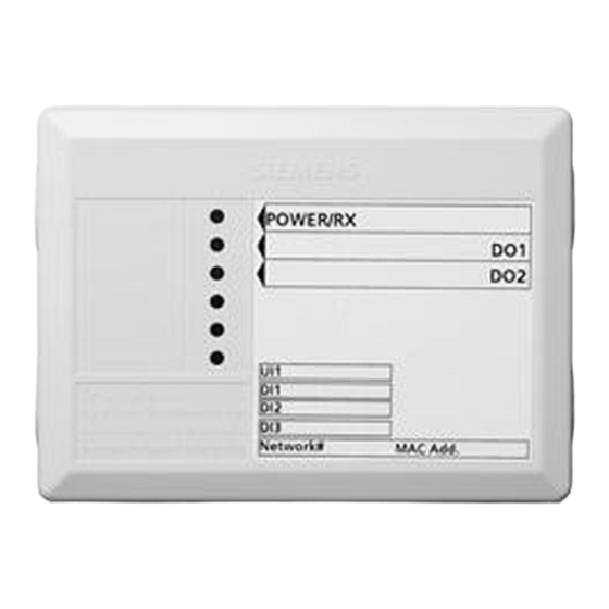
Page 14: Status Leds
OFF indicates unit not powered. Flashing indicates device is successfully transmitting packets on the network. Figure 6: 6 Point Digital PPM with Two Digital Outputs. Figure 7: 12 Point Combination PPM with Three Digital Outputs. Siemens Industry, Inc. 125-5065T 2012-08-06... -
Page 15: Change Of Value Implementation
32.3°F(0.14°C) -13 –165.2°F(-25℃ – 74°C) 4 to 20 mA 200uA 100uA 4 to 20 mA 0 to 10V input 100mV(1%) 50mV 0 to 10V 0 to 10V output 100mV(1%) 30mV 0 to 10V Table 1: Siemens Industry, Inc. 125-5065T 2012-08-06... -
Page 16: Wiring
Wiring Wiring See the Wiring Guidelines Manual (125-3002) for additional wiring information. Figure 9: Power Wiring. Figure 10: FLN 2-wire network interface. Figure 11: FLN 3-wire interface. Siemens Industry, Inc. 125-5065T 2012-08-06... -
Page 17: I/O Configuration Diagrams
I/O Configuration Diagrams Figure 12: AI/DI wiring for 6 point digital. Figure 13: DO wiring for wiring for 6 point digital. Figure 14: Analog input wiring. Figure 15: Universal input wiring. Figure 16: Analog output wiring. Siemens Industry, Inc. 125-5065T 2012-08-06... -
Page 18: Service Information
When troubleshooting, record the problem and what actions were performed immediately before the problem occurred. Being able to describe the problem in detail is important should you need assistance from your local Siemens Solution Partner, Authorized TALON Dealer. To view the status of the MS/TP PPM device and to call up reports for troubleshooting, you can use an operator's terminal and the operator interface or a TALON View workstation. - Page 19 Service Information Reinstalling the Mounting Tabs NOTE: The end with the screw hole slides into the channel first. Figure 17: Reinstalling a DIN Mounting Tab. Siemens Industry, Inc. 125-5065T 2012-08-06...
-
Page 20: Glossary
BACnet Object Browser predictable), or as high information content (where An application that allows you to browse Siemens the opposite conditions apply). Broadly speaking BACnet devices and objects and third-party LEDs, ELs, and VFDs are best suited to the... -
Page 21: Index
Hand-Off-Auto, 12 Change of Value implementation, 15 communication, 11 compatibility wiring with BACnet devices I/O configuration , 17 with Siemens operator workstations, 7 network, 16 power, 16 diagrams board wiring, 16, 17 DIP switch, 13 electrostatic discharge (ESD), 18 Hand-Off-Auto switches, 12... - Page 22 Issued by © 2012 Copyright Siemens Industry, Inc. Siemens Industry, Inc. Technical specifications and availability subject to change without notice. Building Technologies Division 1000 Deerfield Pkwy Buffalo Grove IL 60089 Tel. +1 847-215-1000 Document ID 125-5065T 125-5065T(AA) Edition 2012-08-06...